

Page 1
EN
S15 Camera Manual
Security-Vision-Systems
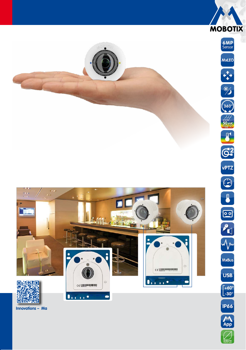
Discreet. Flexible. Hemispheric.
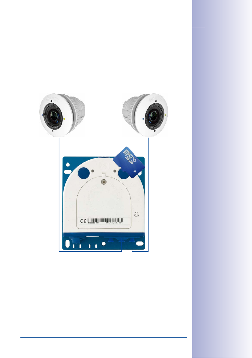
With the S15D FlexMount, one or two sensor modules (6MP/5MP, Day/Night/Night-LPF/Thermal(-TR))
are connected to a concealed camera housing via cables up to 3m/10ft long. Two adjacent rooms
can be discreetly monitored with only one camera. The S15M is the single-lens variant of the S15
FlexMount for installing behind panels that can also be used as door station camera.
S15D FlexMount
Up to 3m/10ft cable
60.182-005_EN_02/2016
Innovations– Made in Germany
The German company MOBOTIX AG is known as the leading pioneer in network camera technology and its
decentralized concept has made high-resolution video systems cost ecient.
MOBOTIX AG• D-67722 Langmeil • Phone: +49 6302 9816-103 • Fax: +49 6302 9816-190 • sales@mobotix.com
www.mobotix.com
S15M FlexMount
Up to 3m/10ft cable
Page 2
2/156
S15 Camera Manual: Contents
THE MOBOTIX INFORMATION CHANNELS
MOBOTIX
MOBOTIX o ers inexpensive seminars that include workshops and practical exer-
For more information, visit www.mobotix.com > Seminars.
cises.
All rights reserved.
trademarks of MOBOTIX AG registered in the European Union, the U.S.A., and other
countries.
Microsoft Corporation.
Bonjour logo, the Bonjour icon,
in the U.S.A. and other countries.
Inc. trademarks.
mentioned herein are trademarks or registered trademarks of the respective owners.
Microsoft, Windows
Support on the MOBOTIX Website
www.mobotix.com/other/Support
The MOBOTIX Video Tutorials
www.mobotix.com/other/
Support/Tutorials
Seminars on MOBOTIX Campus
www.mobotix.com/other/
Partners/Seminars
The MOBOTIX YouTube Channel
www.youtube.com/user/MobotixAG
MOBOTIX Seminars
Copyright Information
MOBOTIX
Linux
, the MX logo,
and
Apple
, the Apple logo,
iPod
iPhone, iPad, iPad mini
is a trademark of Linus Torvalds. All other marks and names
MxManagementCenter
Windows Server
and
iTunes
are trademarks of Apple Inc. registered
and
are registered trademarks of
Macintosh, OSX, iOS, Bonjour
and
iPod touch
MxPEG
are
, the
are Apple
Copyright © 1999-2016 MOBOTIX AG, Langmeil, Germany. Information subject to
change without notice!
Download the latest version of this and other manuals as PDF fi les from
www.mobotix.com> Support > Manuals.
© MOBOTIX AG • Security-Vision-Systems • Made in Germany
www.mobotix.com • sales@mobotix.com
Page 3

Contents
1 Product Overview 10
1.1 S15 FlexMount 10
1.1.1 S15M FlexMount Camera 12
1.1.2 S15D FlexMount Dual Camera 13
1.1.3 Advantages and New Features 16
1.1.4 Hemispheric Technology 18
1.1.5 Decentralized Video System 22
1.2 Technical Specifications 24
1.2.1 S15M Lens Options 24
1.2.2 S15D Lens Options 24
1.2.3 S15D with Thermal(-TR) Sensor Modules 27
1.2.4 Camera Variants– Lenses, Hardware, Image Formats 28
1.2.5 Camera Variants– Software Features 29
1.2.6 Technical Data 30
1.3 Delivered Parts and Dimensions 34
1.3.1 S15D Core (Base Module) 34
1.3.2 Sensor Modules L10-L12* 40
1.3.3 Sensor Modules L20-L23, L22-L25, L32-L38, L43-L51, L65-L76, L135-L160* 42
1.3.4 Sensor Modules L270-L320* 44
1.3.5 BlockFlexMounts L10-L12, L20-L23, L22-L25, L32-L38, L43-L51, L65-L76, L135-L160,
L270-L320* 46
1.3.6 BlockFlexMount CS Mount 48
1.3.7 Sensor Modules Thermal L43, L65, L135 and Thermal-TR079/119/237 50
1.3.8 S15M 52
1.4 Available Accessories 58
1.4.1 Extension for Sensor Module 58
1.4.2 Ceiling/Wall Installation Set 58
1.4.3 Connection Cable for Sensor Module 58
1.4.4 MiniUSB Cable to MiniUSB (Straight/Straight or Straight/Angled) 58
1.4.5 MiniUSB Cable to USB a Socket 59
1.4.6 Ethernet Patch Cable for Bayonet Catch 59
1.4.7 NPA-PoE-Set 59
1.4.8 MX-Overvoltage-Protection-Box 59
1.4.9 MX-NPA-Box 60
1.4.10 MX-GPS-Box 60
1.4.11 MX-232-IO-Box 60
1.4.12 ExtIO Expansion Module 61
1.4.13 Mx2wire+ Media Converter 61
1.4.14 AudioMount 61
1.4.15 DualMount 62
1.4.16 SurroundMount 62
1.4.17 HaloMount 62
1.4.18 SpeakerMount 63
1.4.19 PTMount 63
© MOBOTIX AG • Security-Vision-Systems • Made in Germany
3/156
www.mobotix.com • sales@mobotix.com
Page 4

4/156
S15 Camera Manual: Contents
1.4.20 PTMount-Thermal(-TR) 63
1.4.21 Sealing Ring as Dome Replacement for Sensor Modules L10-L12 64
1.4.22 Other Accessories 64
1.5 MOBOTIX Software 65
1.5.1 Integrated Camera Software (Firmware) 65
1.5.2 MxManagementCenter 66
1.5.3 MOBOTIX App 67
2 Installation 68
2.1 Determining the Installation Position 68
2.1.1 Positioning a Hemispheric Camera 69
2.1.2 S15D FlexMount Installation Options 74
2.1.3 S15M FlexMount Installation Options 81
2.2 Before Mounting 82
2.2.1 Overview of Cable Connections 82
2.2.2 Notes on Cable Lengths and Power Supply 84
2.2.3 Network Connection with MOBOTIX Patch Cable 85
2.2.4 Network Connection with Installation Cable 86
2.2.5 Using Sensor Modules (S15D Only) 86
2.2.6 Using the MiniUSB Cable 86
2.2.7 Using MxBus Modules 87
2.2.8 External Audio Support (Microphone/Speaker) 87
2.2.9 Replacing the MicroSD Card 88
2.2.10 Tools Required for Installation 88
2.2.11 Preparatory Steps 89
2.3 Installing the S15D FlexMount 90
2.3.1 Attaching the S15D Base Module 90
2.3.2 Attaching and Connecting the S15D Sensor Modules 91
2.3.3 Plugging in and Removing Extensions 92
2.3.4 Connecting Network Cables and Additional S15D Cables 93
2.4 Installing the S15M FlexMount 94
2.4.1 Connecting Network Cables and Additional S15M Cables 94
2.4.2 Attaching the S15M Camera Housing 94
2.5 Network and Power Connection, Additional Cables 96
2.5.1 Network Cabling for S15 with Patch Cables 96
2.5.2 Network Cabling for S15 with Installation Cables 97
2.5.3 Connecting Additional Cables 99
2.5.4 Power Supply Using a Switch 100
2.5.5 Power Supply When Connected Directly to a Computer 101
2.5.6 Power Supply with Power-Over-Ethernet Products 101
2.5.7 Variable PoE 102
2.5.8 Camera Startup Sequence 103
© MOBOTIX AG • Security-Vision-Systems • Made in Germany
www.mobotix.com • sales@mobotix.com
Page 5

3 Operating the Camera 104
3.1 Manual and Automatic Operation 104
3.2 First Images and the Most Important Settings 106
3.2.1 Manually Setting Up the Network Parameters in a Browser 106
3.2.2 First Images and the Most Important Settings in the Browser 109
3.2.3 First Images and Network Parameter Configuration in MxMC 111
3.2.4 Starting the Camera with Factory (Network) Settings 114
3.2.5 Starting the Camera with an Automatic IP Address (DHCP) 115
3.3 Adjusting Lens Focus and Inserting a Filter 116
3.3.1 Adjusting Lens Focus (L65-L76/L135-L160 Only) 116
3.3.2 Inserting a Filter 117
3.3.3 Replacing the Dome Against the Sealing Ring (Only Sensor Modules L10-L12) 118
3.4 Virtual PTZ and Full Image Recording 120
3.4.1 Preparing the Virtual PTZ Function 120
3.4.2 Full Image Recording 122
3.4.3 Special S15 Configuration in the Browser 124
3.5 MicroSD Card Recording 134
3.5.1 Introduction 134
3.5.2 Formatting the MicroSD Card 136
3.5.3 Activating MicroSD Card Recording 137
3.5.4 Accessing Data on the MicroSD Card 138
3.5.5 Deactivating Card Recording 138
3.5.6 Using a MicroSD Card in a Dierent MOBOTIX Camera 139
3.5.7 Limitations on Warranty When Using Flash Storage Media 139
3.6 Configuration in the Browser 140
3.6.1 Overview 140
3.6.2 General Browser Settings 142
3.6.3 Configuring the S15D with Thermal(-TR) Sensor Modules in the Browser 143
5/156
3.7 Setting Up an S15D/M FlexMount as Door Station 145
3.7.1 Installation 145
3.7.2 Execute Auto Configuration 146
3.7.3 Setting Up an S15D/M as a Door Station 147
3.8 Additional Notes 148
3.8.1 Do Not Sharply Bend the Connection Cables to the Sensor Modules 148
3.8.2 Reduced Weather Protection When Installing Upside-Down 148
3.8.3 Password for the Admin Menu 148
3.8.4 Permanently Deactivating the Microphone 149
3.8.5 Starting the Camera with the Factory IP Address 149
3.8.6 Resetting the Camera to Factory Settings 149
3.8.7 Activating Event Control and Motion Detection 149
3.8.8 Deactivating Text and Logo Options 150
© MOBOTIX AG • Security-Vision-Systems • Made in Germany
www.mobotix.com • sales@mobotix.com
Page 6
6/156
§
§
S15 Camera Manual: Contents
3.8.9 Deactivating the Camera Reboot 150
3.8.10 Browser 150
3.8.11 Cleaning the Camera and Lens 150
3.8.12 Legal Notes 151
3.8.13 Safety Warnings 151
3.8.14 Online Help in the Browser 152
3.8.15 RoHS Declaration 152
3.8.16 Disposal 152
3.8.17 Disclaimer 153
Manufacturer 155
Legal Notes
Attention – Special Export Regulations Apply! Cameras with thermal image sensors (“thermal cameras”) are subject to the special export regulations of the
U.S.A. and the ITAR (International Trac in Arms Regulation):
• According to the currently applicable export regulations of the U.S.A. and
the ITAR, cameras with thermal image sensors or parts thereof must not
be exported to countries embargoed by the U.S.A. or the ITAR. At present,
this applies to the following countries: Syria, Iran, Cuba, North Korea and
Sudan. The same export ban applies to all persons and institutions listed
in “The Denied Persons List” (see www.bis.doc.gov> Policy Guidance>
Lists of Parties of Concern).
• Under no circumstances can the camera itself or its thermal image sensors
be used in the design, the development or in the production of nuclear,
biological or chemical weapons or in the weapons themselves.
Legal aspects of video and sound recording: You must comply with all data protec
tion regulations for video and sound monitoring when using MOBOTIX products.
Depending on national laws and the installation location of the S15, the recording
of video and sound data may be subject to special documentation or it may be
prohibited. All users of MOBOTIX products are therefore required to familiarize themselves with all valid regulations and comply with these laws. MOBOTIX AG is not
liable for any illegal use of its products.
-
© MOBOTIX AG • Security-Vision-Systems • Made in Germany
www.mobotix.com • sales@mobotix.com
Page 7
Safety Warnings
Installation Instructions:
•
This product must not be used in locations exposed to the dangers of explosion.
• Make sure to install this product as shown in
manual.
•
When installing this product, make sure that you are only using genuine MOBOTIX
parts and MOBOTIX connection cables.
• Make sure that you are installing this product on a solid surface that provides
for a sturdy installation of the fixing elements used.
Electrical installation: Electrical systems and equipment may only be installed,
modified and maintained by a qualified electrician or under the direction and super
vision of a qualified electrician in accordance with the applicable electrical guidelines.
Make sure to properly set up all electrical connections.
Chapter 2, «Installation»
7/156
of this
-
Electrical surges: MOBOTIX cameras are protected against the eects of small elec
trical surges by numerous measures. These measures, however, cannot prevent the
camera from being damaged when stronger electrical surges occur. Special care
should be taken when installing the camera outside of buildings to ensure proper
protection against lightning, since this also protects the building and the whole
network infrastructure.
Max. power consumption of attached extension modules: The power consump
tion of all attached
to the MxBus connector
attached modules must not exceed 4W
PoE class2
If
exceed 1W!
and
required
must not exceed 1W
Never touch the dome or the protective lens covers: Due to the high performance
of the S15, the area of the image sensor can get quite hot, especially when the
ambient temperature is also high. This does not aect the proper functioning of the
camera in any way. For this reason, the product must not be installed within the
reach of persons without domes or protective lens covers.
Only exchange sensor modules when powered o: Make sure that the camera‘s
power supply has been disconnected before attempting to exchange any sensor
modules.
Network security: MOBOTIX products include all of the necessary configuration
options for operation in Ethernet networks in compliance with data protection laws.
The operator is responsible for the data protection concept across the entire system.
The basic settings required to prevent misuse can be configured in the software and
are password-protected. This prevents unauthorized parties from accessing these
settings.
MxBus modules
is used,
the power consumption of all attached modules must not
If thermal sensor modules are used with this camera,
the power consumption of all attached modules (MxBus and USB)
.
must
not exceed 3W
and
the USB connector, the
,
if the camera is powered by PoE class3
. When attaching modules
power consumption of all
PoE Class3 is
-
-
.
© MOBOTIX AG • Security-Vision-Systems • Made in Germany
www.mobotix.com • sales@mobotix.com
Page 8

8/156
S15 Camera Manual
FOREWORD
Dear MOBOTIX customer,
Congratulations on purchasing a professional and state-of-the-art HiRes network camera
“Made in Germany.” MOBOTIX is proud to present the S15 FlexMount, a weatherproof
and flexible system characterized above all by its extremely discreet installation options.
In the dual camera S15D variant one or two sensor modules (lens with a sensor board,
LEDs and microphone) are connected to the base module using cables that can be up to
three meters long. The flat housing with integrated long-term flash memory and external
connectors (Ethernet, MiniUSB, MxBus, audio) can be installed discreetly and with optimal
protection behind a wall or ceiling panel so that only the lenses are visible in the room.
Sensor modules are available with 5MP and 6MP resolution: from tele lens to Hemispheric,
each available as day or night models, in black or white.
The BlockFlexMounts represent the same sensor modules in a dierent housing that has
been designed especially for integration into any given structure or device. The additional
mounting options (DualMount, SurroundMount, HaloMount, PTMount) provide the highest
flexibility when installing the modules.
The S15M camera variant has a hemispheric sensor module (day or night) that is integrated
into the camera housing. This camera can also be placed discreetly and securely behind
walls and ceilings or stainless steel panels (using the AudioMount, for example). If a speaker
is required, why not use the SpeakerMount for easy installation into ceilings or walls?
The introduction of the newest sensor technology with increased light sensitivity in combi
nation with the new HD Premium lenses (aperture f/1.8) not only generates more brilliant
images with up to 3072x2048 (6MP image sensor) or 2592x1944 (5MP image sensor), it
also delivers color images of higher quality under lowlight conditions.
The new model variant
a high-end thermal imaging sensor, which can reliably detect moving objects even in
total darkness. The
detecting temperatures in the image or in measurement windows that exceed or drop
below the specified temperature.
The MxManagementCenter video management software, which is tailored to MOBOTIX
cameras, can be downloaded from the MOBOTIX website at no cost: www.mobotix.com>
Support> Sof tware Downloads. The tutorial for the application is available under Support>
Tutorials. MOBOTIX also provides a mobile solution for the iPad, iPhone and iPod Touch
iOS devices. Search for “MOBOTIX AG” in the App Store to find the free app.
If you still have any questions, our support and international sales sta are available at
intl-support@mobotix.com from Monday to Friday, 8 a.m. to 6 p.m. (German time).
We would like to thank you for your trust and wish you all the best with your new MOBOTIX
camera S15 FlexMount.
M15-Thermal
M15-Thermal-TR (TR = Thermal Radiometry
© MOBOTIX AG • Security-Vision-Systems • Made in Germany
supplements the proven MOBOTIX technology by
) can trigger alarms when
www.mobotix.com • sales@mobotix.com
-
Page 9
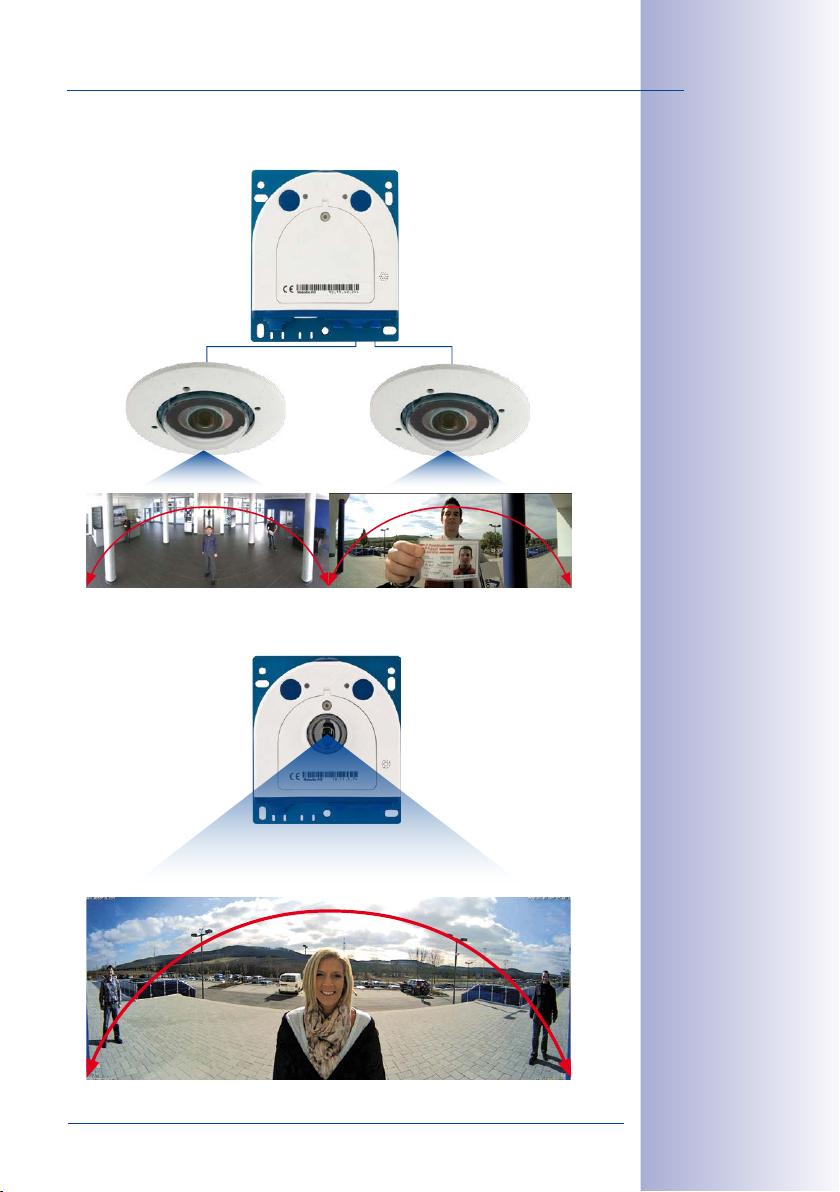
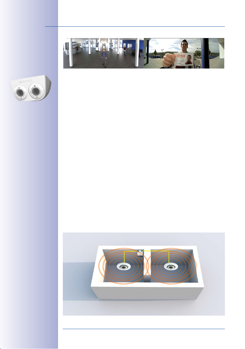
S15D – One Camera, Two Surveillance Areas:
Indoor Entrance Area (Left) and Outdoor Entrance Area (Right)
180° Panorama180° Panorama
S15M – Camera with Hemispheric Sensor Module for Concealed
Installation Behind a Wall or Ceiling Panel
180° Panorama
9/156
© MOBOTIX AG • Security-Vision-Systems • Made in Germany
www.mobotix.com • sales@mobotix.com
Page 10
10/156
D
i
a
m
e
t
e
r
:
5
0
m
m
/
2
i
n
S15 Camera Manual: Product Overview
1 PRODUCT OVERVIEW
1.1 S15 FlexMount
Perfect When Discretion Is Needed
Some application scenarios benefit from a surveillance camera that is present, but does
not attract attention. Available in both single-lens and dual versions, the cameras feature
a discreet appearance, enabling a flexible range of applications.
The easily concealable camera housing makes every S15 system the ideal solution wher
ever discreet design and appearance are paramount. Digital network cameras without
mechanical moving parts require low maintenance. In addition, they are silent when
panning and focusing on a specific image area. As a result, typical applications for these
cameras are installations in hotels and restaurants, public and private buildings, waiting
rooms, showrooms, parking garages, storage rooms and exhibition booths.
Fast, Simple Cabling
The MOBOTIX S15 FlexMount requires just one cable for data and power to connect to a
PoE switch and thereby to any expandable Ethernet network. There are two options for a
weatherproof connection of the network cable to the housing. A MOBOTIX patch cable up
to 10meters in length can be plugged externally into the housing from below and secured
with a weatherproof bayonet catch, or the eight individual strands of the installation cable
can be attached directly to the LSA cutting clamp inside the camera housing.
A number of additional devices can be used together with the S15. They are connected
via a network switch or directly to the camera housing via a MxBus or MiniUSB cable (for
example, ExtIO, MOBOTIX interface boxes, audio devices, flash drives or UMTS/WiFi USB
modems). If the network switch also features an Internet connection, it can be used for
encrypted access to the camera footage from anywhere in the world.
The entire camera plus cables and sensor modules are weatherproof () and operate in
a temperature range of –30 to +60 °C/–22 to +140 °F. Because the S15 never fogs up and
does not require any heating, it can be operated all year round with power supplied via a
standard PoE network cable. Power consumption is less than five watts.
-
© MOBOTIX AG • Security-Vision-Systems • Made in Germany
www.mobotix.com • sales@mobotix.com
Page 11
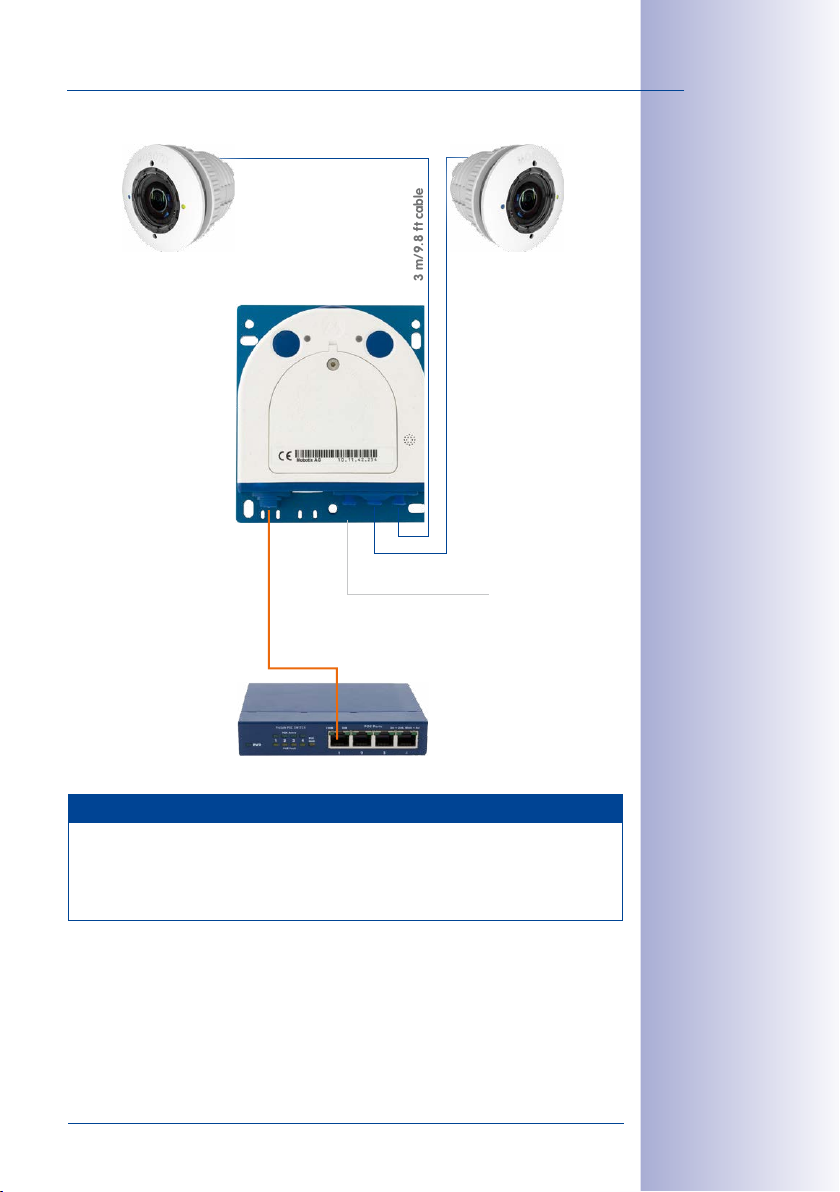
S15 FlexMount
3m/9.8ft cable
3m/9.8ft cable
MiniUSB
11/156
Sensor modules
including status LEDs
and microphone
Ethernet patch cable
PoE switch
Note
S15D Complete Sets
MOBOTIX also oers fully equipped
more information, see the MOBOTIX webseite (www.mobotix.com) or contact your
MOBOTIX partner directly.
© MOBOTIX AG • Security-Vision-Systems • Made in Germany
www.mobotix.com • sales@mobotix.com
S15D sets
with one or two sensor modules. For
Page 12
12/156
S15 Camera Manual: Product Overview
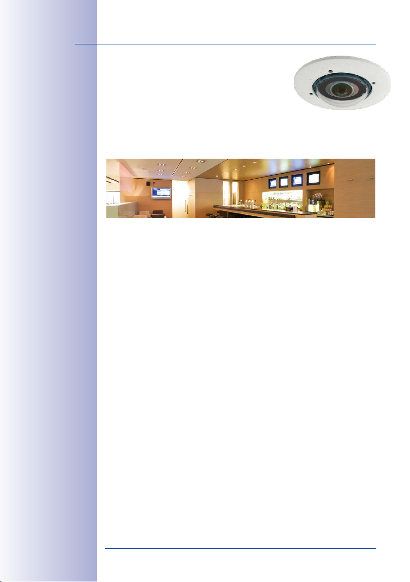
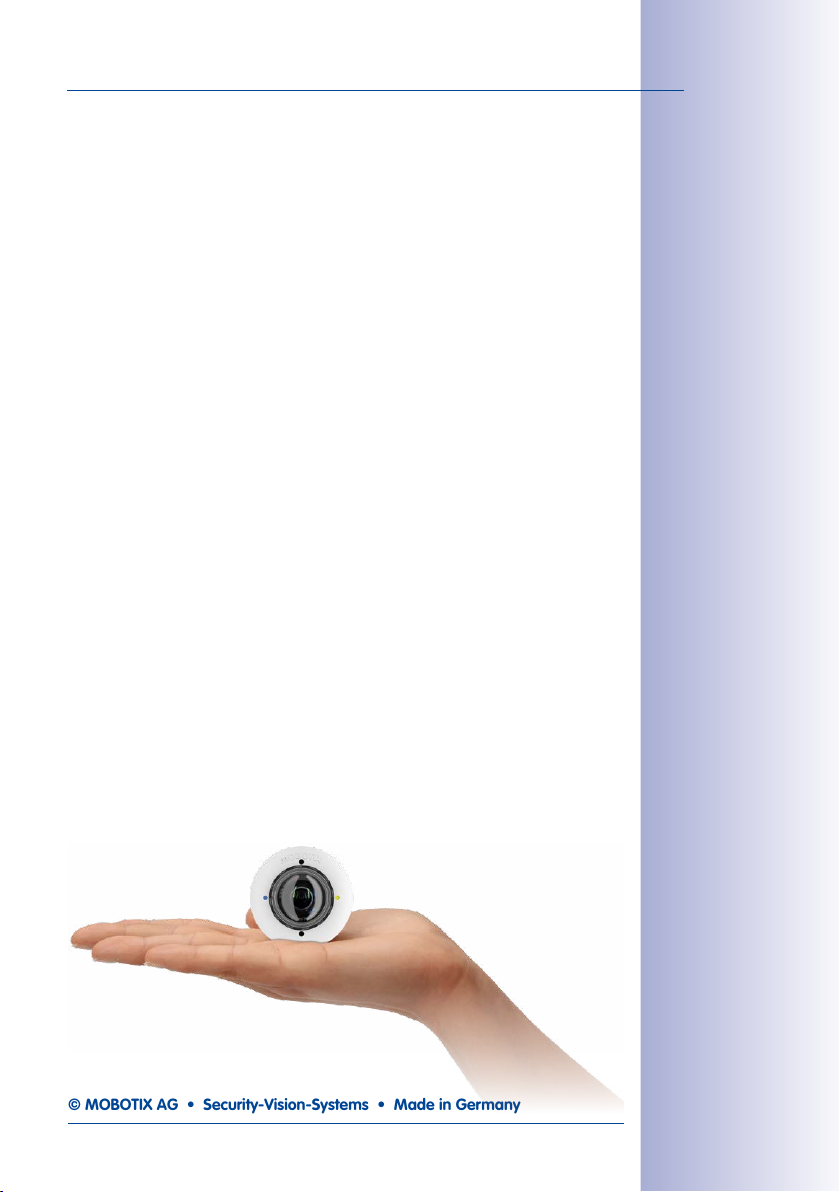
1.1.1 S15M FlexMount Camera
Almost Completely Concealable Hemispheric Camera
The S15M is the compact single-lens version of the S15 series (M = mono). With this version, (only
one) hemispheric lens (L10 – 6MP, L12 – 5MP) is screwed directly to the camera housing, which
can be concealed behind a cover or cladding (for example, stainless steel) up to 6.4mm in
thickness. Thicker surfaces may also be suitable for mounting the S15M if they can be hollowed
out accordingly.
New 6MP/5MP Images Sensors In The Day Or Night Model
The S15M features a high-resolution color or black and white sensor with 3072x2048 (6MP) or
2592x1944 (5MP) pixels for installation under all lighting conditions (day = color, night = black
and white). If needed, external microphone and/or speaker units can be directly connected to
the camera via suitable IO terminals.
© MOBOTIX AG • Security-Vision-Systems • Made in Germany
www.mobotix.com • sales@mobotix.com
Page 13
S15 FlexMount
13/156
1.1.2 S15D FlexMount Dual Camera
Dual Images Up to Twelve Megapixels in Size
The S15D (D = dual), the second version, features one or two sensor modules, each with an
integrated microphone and two status LEDs, which can be connected to the core module via
cables up to 3meters long. The sensor modules are supplied preassembled for ceiling or wall
mounting. The visible external part of the sensor module is available in white or black, enabling
it to blend into most installation environments.
Each with one integrated microphone
and two status LEDs
3m cable
3m cable
-
On www.mobotix.com
go to Products > S15
FlexMount and open the
basket. It contains a
Product Congurator,
Use this to order the
required parts in any of
the available colors.
The S15D can take up to two HiRes image sensors with 3072x2048 (6MP) or 2592x1944 (5MP)
pixels, which can be combined to output a color dual image up to 12 megapixels in size. The
system can be fitted with any combination of day, night, night LPF, Thermal(-TR) or BlockFlexMount
sensor modules. The maximum frame rate can be up to 30 frames per second, depending on
the resolution selected.
© MOBOTIX AG • Security-Vision-Systems • Made in Germany
www.mobotix.com • sales@mobotix.com
Page 14
14/156
S15 Camera Manual: Product Overview
Day and Night Sensor in One Camera
The dierence between a MOBOTIX day/night camera and the standard versions is primarily
that it continuously uses two adjacent sensor modules rather than relying on a mechanical
filter switch, which can be costly to maintain. The other advantage is much better image
quality in poor lighting conditions, as the camera uses a real infrared-sensitive, blackand-white image sensor instead of the usual color sensor with electronic color fade-out,
whereby the infrared sensitivity is reduced through integrated color filters.
Dual Hemispheric Camera S15D
When an S15D with two hemispheric sensor modules is deployed, they can be installed in
dierent mounting positions (ceiling, wall, floor), even in dierent rooms, if needed. Each
sensor module oers the full range of functions provided by a hemispheric camera. The
day/night versions of the sensor modules can be freely combined in installation (including
automatic day/night switching for the same viewing angle).
Thermal-
and
The
thermal image sensors, which further expand the range of application scenarios. You can
use two thermal sensor modules as a dual thermal imaging camera, for example, or a
combination of a Thermal-TR and an optical sensor module for measuring temperatures
and delivering color images at the same time. This means that the S15D combines the
proven MOBOTIX sensors and event processing capabilities with thermal imaging technology, which can reliably detect moving objects even in total darkness.
Thermal-TR sensor modules
have permanently installed high-end
© MOBOTIX AG • Security-Vision-Systems • Made in Germany
www.mobotix.com • sales@mobotix.com
Page 15
S15 FlexMount
1
2
3
Separate Housing and Lens Installation – Weatherproof According to IP66
The flat housing of the S15 FlexMount, including long-term flash memory (MicroSD , SDXC)
and all internal and external connectors (Ethernet, MiniUSB, MxBus, microphone, speaker),
can be installed discreetly and with optimal protection behind a wall or ceiling panel.
Only the small round fronts of the sensor modules, which are 50mm in diameter, are
visible in the room.
15/156
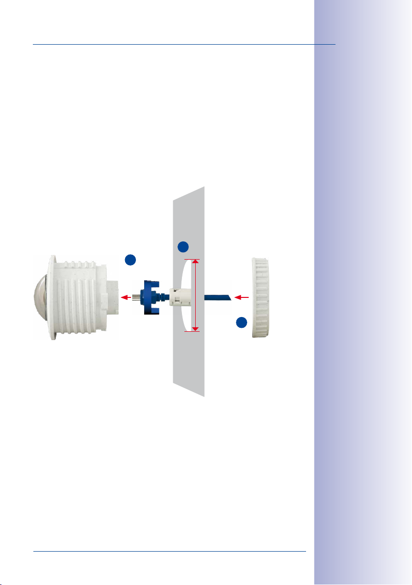
Mounting the recessed sensor modules of the S15D is extremely easy: Plug the connec
tion cable into the sensor module and secure it with the bayonet catch, attach the hinged
ferrite, drill a circular hole (diameter: at least 43mm), feed through the cable and sensor
module from the front, secure it with a nut, plug the connection cable into the core mod
ule and secure it. You‘re done!
Step 1:
Plug in connection cable and
secure with bayonet catch, attach
hinged ferrite
Flexible and Future-Proof
The system can easily be matched to suit the location‘s requirements, thanks to a range
of available sensor modules. Replacing the sensor modules at a later stage to change
the focal lengths is quick and easy, as is upgrading from one to two sensor modules.
Step 2:
Drill hole (min. of 43mm), feed
through cable with sensor
module
Min. diam. 43mm/1.67in
Step 3:
Secure sensor module with nut
-
-
Sensor modules can
be replaced any time
© MOBOTIX AG • Security-Vision-Systems • Made in Germany
www.mobotix.com • sales@mobotix.com
Page 16

16/156
S15 Camera Manual: Product Overview
1.1.3 Advantages and New Features
The high-resolution S15 FlexMount is a universally deployable, highly innovative and easily concealable camera system. A powerful successor to the S14, the S15 features fivemegapixel image sensors. Since the live or recorded images displayed by an S15 sensor
have a maximum size of 3072x2048 (6MP) bzw. 2592x1944 (5MP) pixels, the S15 is clearly
superior to the previous model in terms of image quality and frame rate.
Smooth HiRes Video Streams
The modified hardware of the S15 transmits the camera‘s video streams even more smoothly
than the high-performance S14, even when high resolution is required. Since image streams
of 16 frames per second and higher are perceived as smooth video by the human eye,
the maximum frame rate is limited to 30 frames per second (when using MEGA resolu
tion of 1280x960) in order to provide sucient camera processing power for other tasks.
Conclusive Still Images
Thanks to the proprietary MxPEG video codec developed exclusively for MOBOTIX cameras,
the cameras oer the advantage that a recording can be paused at any given point and
still provide meaningful and useful snapshots due to the absence of distortion. This is
essential for security applications and allows individuals or license plates to be identified,
for example. In contrast, the H.264 standard, which was developed for feature movies
and is favored by some video security providers, cannot achieve this with the required
level of quality.
Good Color Images Even in Low Light
The more light-sensitive an image sensor is, the better the image quality, especially when
the ambient light level is low, such as at dusk and in heavy rainfall. The S15 oers the best
MOBOTIX image quality that is currently available thanks to the light sensitivity provided
by the five-megapixel color sensor that is four times higher than that of the previous
three-megapixel color sensor.
-
Black and White Images Now Up to 6Megapixels in Size
The S15 is the first MOBOTIX camera worldwide to also feature a 6MP night sensor that
can deliver black and white images up to 3072x2048 pixels in size. This means that the
image resolution is more than four times higher than the predecessor’s night image sen
sor with 1.3 megapixels.
World’s first Dual Thermal Camera
The new thermal sensor modules measure the thermal radiation of objects, delivering
clear thermal images even in absolute darkness. Together with the MxActivitySensor, they
can reliably detect motion in images at night– where only changes in position will trigger
a signal. Objects moving on the spot do not trigger a signal. The thermal sensor modules
also have an advantage during the day, as they can detect moving objects in shadows,
semi-darkness, smoke or behind bushes.
© MOBOTIX AG • Security-Vision-Systems • Made in Germany
www.mobotix.com • sales@mobotix.com
-
Page 17
S15 FlexMount
Thermal Radiometry – Measuring Temperatures and Triggering Alarms
The
M15-Thermal-TR (TR = Thermal Radiometry
images and detect movements; this model variant can measure temperatures and trigger
alarms. This is the result of using a calibrated thermal sensor, which can measure the
temperatures in the entire image or in measurement windows.
MxActivitySensor
The S15 provides an activity-controlled image analysis sensor as standard for detecting the
movements of people and objects in a defined surveillance area (full image or section).
The MxActivitySensor delivers reliable results particularly in outdoor area applications, in
contrast to video motion detection that continues to be available and that registers all
image changes in defined video motion windows. In the monitored area, the camera
distinguishes between the continuous movements of vehicles, persons or objects that
trigger an alarm and movements that do not set o an alarm such as shadows, changing
light conditions and trees swaying in the wind.
MOBOTIX Mounts– Flexible Installation Options
Whether in ceilings, behind faceplates or built into other devices, the MOBOTIX mounts
provide flexible solutions for every application scenario. The HaloMount installs sensor
modules into ceilings as easily as halogen spot lamps, the SpeakerMount with integrated
speaker provides the audio output. If two sensor modules are to be installed side-by-side
with the same viewing direction, you can use the DualMount (e.g. for Day/Night sensor
modules). Two sensor modules looking into opposite directions? This is calling for the
SurroundMount (e.g. for long hallways). The AudioMount, complete with installed S15M
is glued to the back of a faceplate in order to provide door station functionality. The
BlockFlexMount sensor modules allow installing the S15D with up to two sensor modules
into any device.
) can do even more than to record thermal
17/156
Low Power Consumption in Accordance with the PoE Standard (IEEE 802.3af)
An S15 uses no more power than its predecessor (typically 4.5watts), despite the new
sensor technology. Adjusting the PoE class via the camera software also enables the use
of PoE switches that cannot be operated on all ports with PoE class 3 (up to max. 12.95V).
If an S15D is used with one or two thermal sensor modules, PoE Class3 is required.
© MOBOTIX AG • Security-Vision-Systems • Made in Germany
www.mobotix.com • sales@mobotix.com
Page 18
18/156
S15 Camera Manual: Product Overview
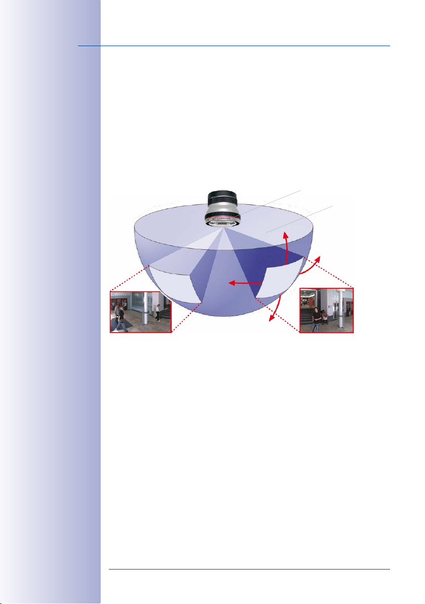
1.1.4 Hemispheric Technology
Featuring one (S15M) or two hemispheric lenses (S15D), oers all the image views known
from MOBOTIX‘ other hemispheric cameras, including
Panorama, Full Image, Normal
view can be displayed as a dual image that combines both sensor modules.
The primary components of a hemispheric camera include a fisheye lens, a high-resolution
image sensor, and image correction software that is integrated into the camera. Using
an ultra-wide angle lens, the hemispheric camera captures a 180°-hemispheric image
of the room and projects it onto a high-resolution image sensor.
and
Surround
vPTZ 1 vPTZ 2
Panorama, Panorama Focus, Double
. What‘s new on the S15D is that the selected
L12 (fisheye)
Hemispheric panorama view
When ceiling mounted, the image area of the hemispheric camera covers the entire room.
The image in the hemisphere is convex, particularly near the image borders. These image
sections are corrected for the viewer by the integrated distortion correction software,
allowing a view of the scene from the usual perspective. The virtual PTZ feature allows
you to enlarge or move image sections within the hemisphere just like PTZ camera, yet
without the need for mechanical moving parts. Hemispheric cameras lack mechanical
moving parts and require low maintenance. In addition, they are silent when panning
and focusing on a specific image area.
© MOBOTIX AG • Security-Vision-Systems • Made in Germany
www.mobotix.com • sales@mobotix.com
Page 19
S15 FlexMount
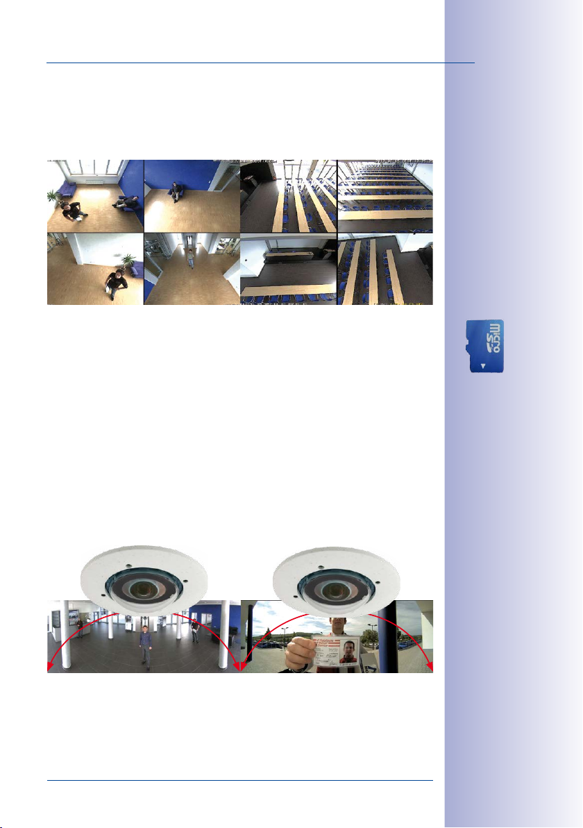
Handle Several Image Sections at Once
One or more image sections can be corrected for perspective in the hemispheric view,
allowing you to monitor and record several dierent areas of a room at the same time,
something that a mechanical PTZ camera is not capable of doing.
Everything Stored in the Recording
Traditional optical PTZ cameras can only record what is being viewed live. The virtual PTZ
feature from MOBOTIX allows users to pan to other areas at a later stage in the recording
because the entire room can be recorded as a hemispheric image.
S15D: Perfect Overview in Two Rooms, Day and Night
A world first, the S15D provides the option of using two hemispheric sensor modules within
a single camera. This way, two entirely separate spaces – next to or on top of each other,
indoors or outdoors – can be secured simultaneously using just one camera.
19/156
The S15D can also be used as a hemispheric day/night camera. The black-and-white and
color sensor modules are mounted directly next to each other so they cover the same
area (we recommend an installation with DualMount MOBOTIX accessory). The camera
automatically chooses the best available mode depending on the lighting conditions: either
the color sensor with daylight lens or the black and white image sensor with infrared lens
180° Panorama180° Panorama
© MOBOTIX AG • Security-Vision-Systems • Made in Germany
www.mobotix.com • sales@mobotix.com
Dual image up to 12
megapixels in size
Page 20
20/156
S15 Camera Manual: Product Overview
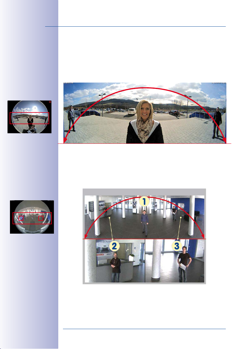
Special Hemispheric Image Views
Panorama
The hemispheric image (original full image) can also be transformed into an ultra-wide
angle panoramic view if the camera is mounted on a wall, providing a view of the room
without any blind spots from wall to wall. It oers a substantially better view of the scene,
compared to other cameras, and it also results in the need for fewer cameras overall.
No Blind Spots from Wall to Wall and from Floor to Ceiling
Panorama Focus
Maximum room overview while simultaneously viewing detail in a single image. A hemi
spheric sensor module can also provide two additional views so that you can focus on
two detail scenes simultaneously in addition to the panorama view.
Panorama Focus – three views simultaneously
-
Original full image
High-resolution 180° panorama
Virtual PTZ 1 Virtual PTZ 2
© MOBOTIX AG • Security-Vision-Systems • Made in Germany
www.mobotix.com • sales@mobotix.com
Page 21
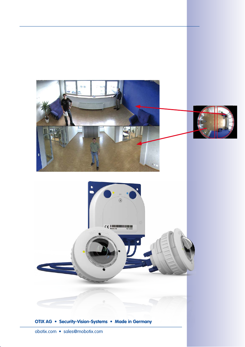
S15 FlexMount
Double Panorama
When the camera is mounted in the center of the ceiling in a room, the “Double Panorama”
display mode provides a corrected panorama image of both halves of the room. It corresponds roughly to the situation of personally standing in the middle of the room and being
able to look both forwards and backwards at the same time. This is a superb overview
for the user – provided by a single sensor module.
21/156
Original full image
© MOBOTIX AG • Security-Vision-Systems • Made in Germany
www.mobotix.com • sales@mobotix.com
Page 22
22/156
S15 Camera Manual: Product Overview
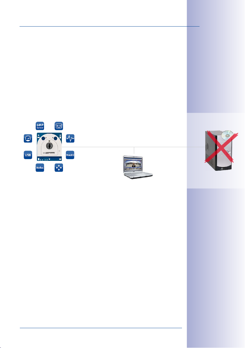
1.1.5 Decentralized Video System
Usually, cameras only supply images, while processing and recording take place later
on a central PC using video management software. This centralized structure has too
many limitations for high-resolution video systems since it requires high network bandwidth
and the PC processing power is insucient when using several high-resolution cameras.
Due to the large number of computers and servers required, traditional centralized systems
are therefore becoming less suitable and cost eective.
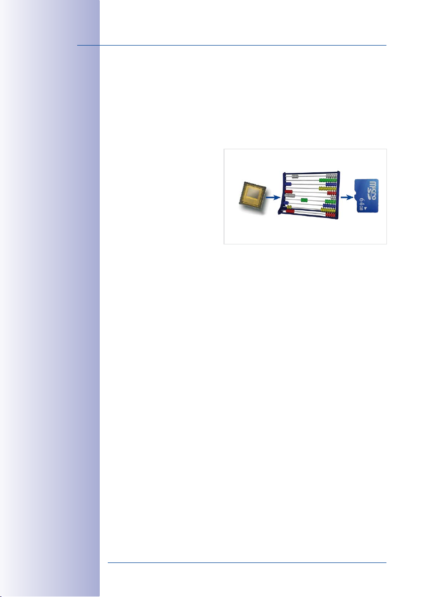
As part of the decentralized
MOBOTIX concept, every camera
features a high-speed processor,
and, if necessary, digital long-term
flash memory (MicroSD card) can
be integrated to provide several
days of recording time. The com
puter or video control center is
required only to view and control
the cameras, not to evaluate and
record video. This means that you do not have to rely on expensive, overloaded video
management software as most of the important functions that require a large amount of
processing power are integrated into the MOBOTIX cameras themselves.
Integrated sensors enable MOBOTIX cameras such as the S15 to automatically detect
when an event has occurred. If necessary, the cameras will respond immediately with an
alarm sound and will establish a direct video and sound connection to a control room.
The S15 is equipped with a shock detector as standard (for all IT and Secure models).
For example, if the camera receives a blow to the housing, it can simultaneously take a
video of the oender, trigger a sound alarm and notify the security company by a SIP call.
Due to the build quality and absence of moving parts, MOBOTIX cameras are extremely
tough. This typically allows them to stay fully operational especially when they are subject
to strong vibrations.
All MOBOTIX cameras are backlight-proof and are not adversely aected by the glare
from direct sunlight. They deliver meaningful, detailed images at all times as the camera
software supports easy programming of independent exposure windows, making them
ideal for rooms with large glass fronts.
In the event of an alarm, MOBOTIX S15 camerascan also record lip-synchronous audio. The
cameras therefore play an important role in analyzing and clarifying a situation. Thanks
to an integrated speaker and microphone, each individual camera can also be used for
bidirectional communication (two-way video communication), so you can easily use the
MOBOTIX App with your iPhone or iPad on the road.
-
6MP/5MP
MOBOTIX camera
CMOS
Image analysis
CPU
MicroSD
Recording
© MOBOTIX AG • Security-Vision-Systems • Made in Germany
www.mobotix.com • sales@mobotix.com
Page 23
S15 FlexMount
The decentralized MOBOTIX video solutions are superior to traditional systems in all major
aspects. They are also considerably cheaper to operate since they require
• Fewer cameras due to the more accurate detail of panorama images with mega
pixel technology
•
Fewer recording devices because in the decentralized system, ten times the standard
number of cameras can be used to record high-resolution HDTV video with sound
on one computer/server simultaneously
• Lower network bandwidth because everything is processed in the camera itself
and the high-resolution images therefore do not have to be constantly transported
for analysis
MOBOTIX System
Decentralized and secure
23/156
-
Recording software
MicroSD integrated
© MOBOTIX AG • Security-Vision-Systems • Made in Germany
www.mobotix.com • sales@mobotix.com
PC as storage device
Page 24
24/156
lens L20, image format 4:3
lens L23, image format 4:3
*S15M with 6MP
image sensor available later in 2015
S15 Camera Manual: Product Overview
1.2 Technical Specifications
1.2.1 S15M Lens Options
Since MOBOTIX cameras are backlight-proof, none of the lenses requires a mechanical
auto iris. This makes the cameras extremely robust and maintenance-free.
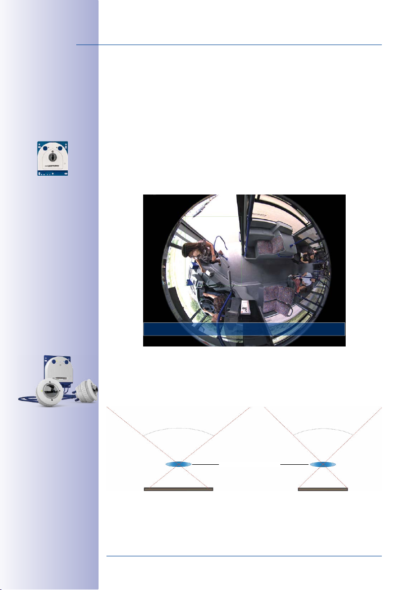
S15M with L10* (6MP) or L12 (5MP) Hemispheric Fisheye Lens
The S15M is shipped with one hemispheric fisheye lens and is available in a day or night
version, making it ideal for installing behind covers or this walls. Combined with the
«AudioMount»
station.
(microphone and speaker integrated), you can set up an alternative door
Full image with L10-L12 fisheye in public transit bus
1.2.2 S15D Lens Options
One or two optical image sensors can be used with the S15D (in the form of sensor modules
or as BlockFlexMount). The image sensors are available as 6MP and 5MP image sensors
with dierent angles of view:
105° 92°
MOBOTIX lens L20-L23
6MP image sensor (1/1,8“)
5MP image sensor (1/2,5“)
© MOBOTIX AG • Security-Vision-Systems • Made in Germany
www.mobotix.com • sales@mobotix.com
Page 25
Technical Specifications
Focal Lengths of MOBOTIX Lenses
The focal lengths of MOBOTIX lenses are always relating to 35mm camera format.
For example, the MOBOTIX L20-L23 Super Wide-Angle lens has a true focal length
of 3.6mm. Converted to 35mm format, this translates to a 20mm lens on a 6MP
image sensor and a 23mm lens on a 5MP image sensor. You can use this focal
length to easily compare image formats and angles of view. In addition, you can
set this value on common 35mm or digital still cameras to the focal length (Lxx) of a
MOBOTIX lens to check if the resulting image suits the requirements for this camera.
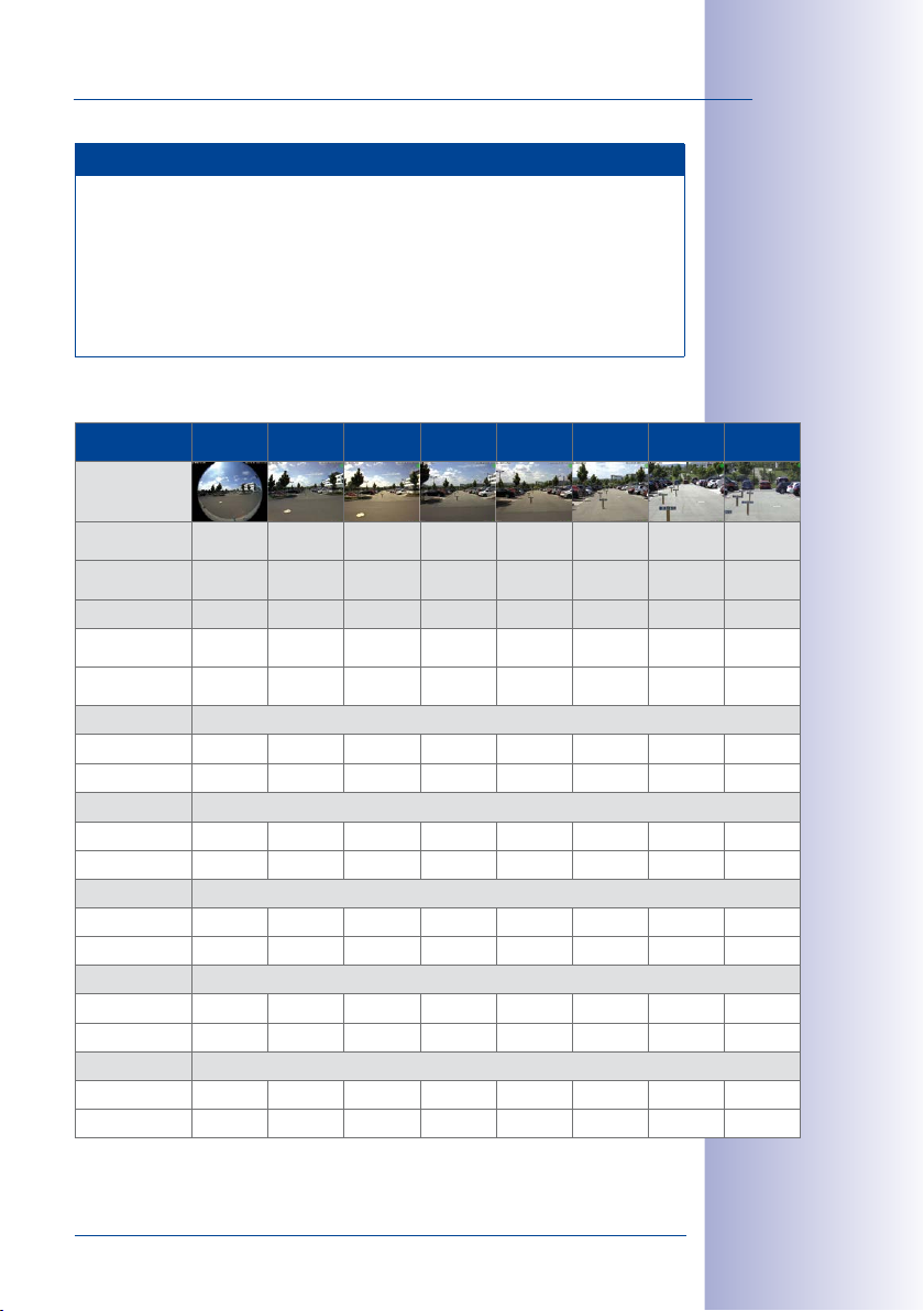
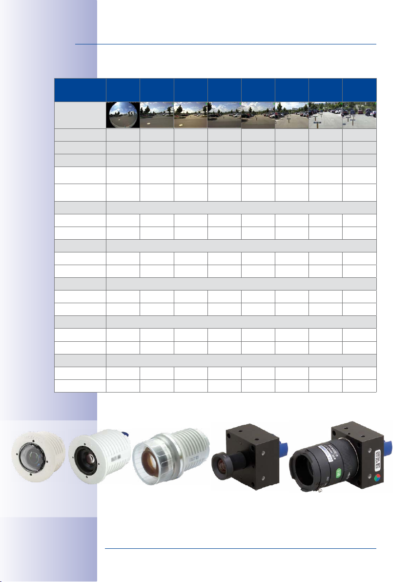
Lenses for S15D Modules with 6MP Image Sensor
Lenses 6MP
Sensors
Original image
(image format
4:3)
Focal length
(35mm equiv.)
Nominal focal
length
Aperture 2.0 1.8 1.8 1.8 1.8 1.8 1.8 2.5
Horiz. angle of
view
Vert. angle of
view
Image width ∞ 2.5 2.0 1.2 0.8 0.6 0.3 0.1
Image height ∞ 1.6 1.3 0.8 0.6 0.4 0.2 0.1
Image width ∞ 12.6 10.0 5.8 4.1 2.8 1.3 0.7
Image height ∞ 8.0 6.6 4.1 3.1 2.0 1.0 0.5
Image width ∞ 25.1 20.0 11.5 8.3 5.5 2.6 1.3
Image height ∞ 15.9 13.2 8.3 6.1 4.1 1.9 1.0
Image width ∞ 50.3 40.0 23.1 16.6 11.1 5.3 2.6
Image height ∞ 31.8 26.5 16.6 12.2 8.1 3.9 1.9
Image width ∞ 125.7 100.0 57.7 41.4 27.7 13.2 6.6
Image height ∞ 79.5 66.2 41.4 30.6 20.3 9.6 4.8
L10 L20 L22 L32 L43 L65 L135 L270
10mm 20mm 22mm 32mm 43mm 65mm 135mm 270mm
1.6mm 3.6mm 4.1mm 6.1mm 7.9mm 11.9mm 23.7mm 50mm
180° 103° 90° 60° 45° 31° 15° 8°
180° 77° 67° 45° 34° 23° 11° 6°
At 1 m distance
At 5 m distance
At 10 m distance
At 20 m distance
At 50 m distance
25/156
© MOBOTIX AG • Security-Vision-Systems • Made in Germany
www.mobotix.com • sales@mobotix.com
Page 26
26/156
Lenses with
5MP Image
Sensor
Original image
(image format
4:3)
35mm equiv. 12mm 23mm 25mm 38mm 51mm 76mm 160mm 320mm
True focal length 1.8mm 3.6mm 4mm 6mm 8mm 12mm 25mm 50mm
Aperture 2.0 1.8 1.8 1.8 1.8 1.8 1.8 2.5
Horizontal angle
of view
Vertical angle
of view
Image width ∞ 2.1 1.7 1.0 0.7 0.5 0.2 0.1
Image height 11.3 1.3 1.2 0.7 0.5 0.4 0.2 0.1
Image width ∞ 10.4 8.7 5.2 3.6 2.4 1.1 0.6
Image height 56.7 6.7 5.9 3.7 2.7 1.8 0.9 0.4
Image width ∞ 20.7 17.4 10.3 7.2 4.9 2.3 1.1
Image height 113.4 13.5 11.9 7.5 5.4 3.6 1.7 0.9
Image width ∞ 41.4 34.7 20.6 14.5 9.7 4.6 2.3
Image height 226.9 27.0 23.7 14.9 10.8 7.2 3.4 1.7
Image width ∞ 103.6 86.8 51.5 36.2 24.3 11.4 5.7
Image height 567.1 67.5 59.3 37.3 27.0 18.0 8.6 4.3
S15 Camera Manual: Product Overview
Lenses for S15D Modules with 5MP Image Sensor
L12 L23 L25 L38 L51 L76 L160 L320
180° 92° 82° 55° 40° 27° 13° 7°
160° 68° 61° 41° 30° 20° 10° 5°
At 1m distance
At 5m distance
At 10m distance
At 20m distance
At 50m distance
Sensor module
L10-L12
Types of Optical Sensor Modules
Sensor module
L20-L23 bis L135-L160
Sensor module
L270-L320
BlockFlexMount
L10-L12 to L270-L320
BlockFlexMount
CS-Mount (without lens)
© MOBOTIX AG • Security-Vision-Systems • Made in Germany
www.mobotix.com • sales@mobotix.com
Page 27
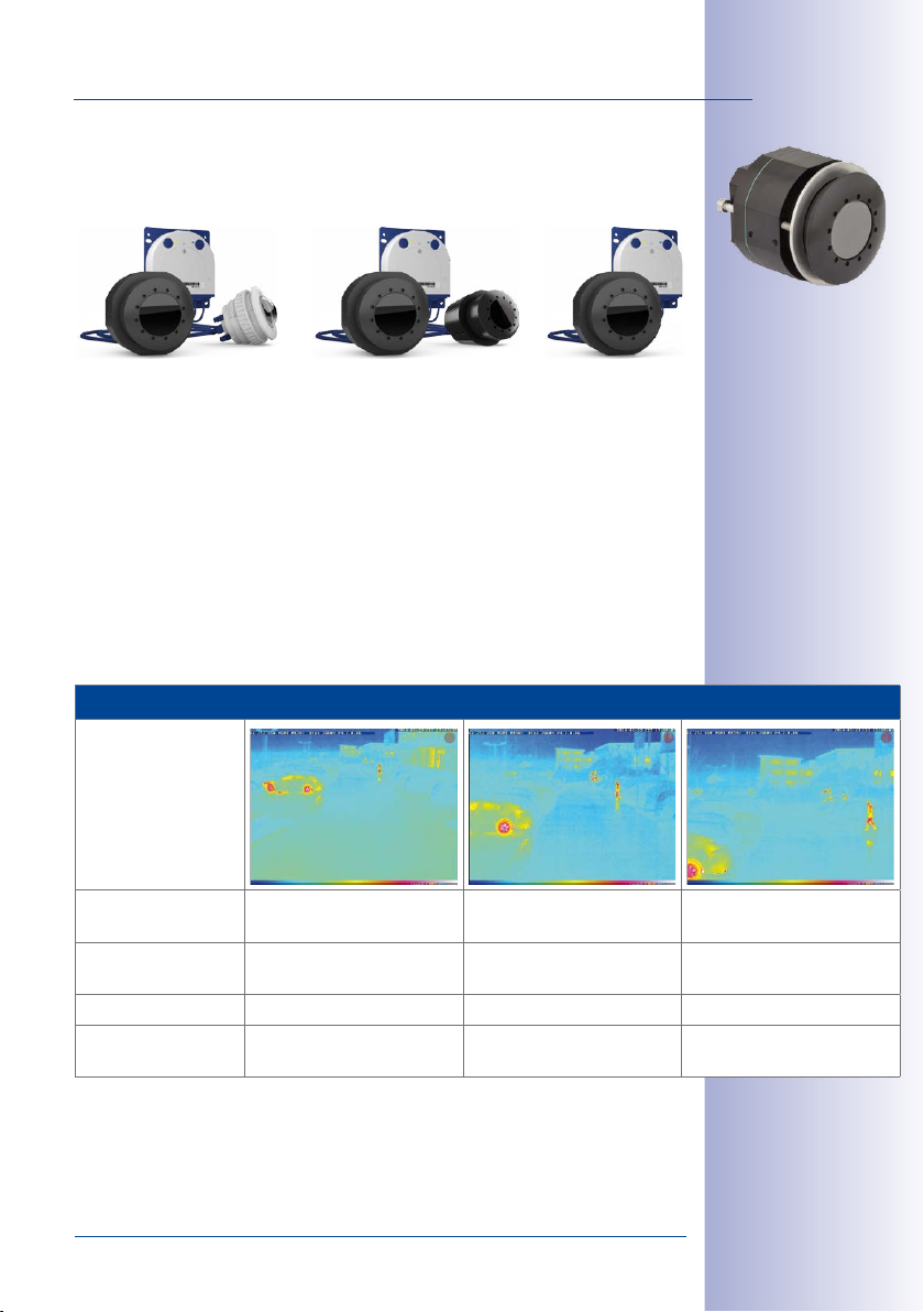
Technical Specifications
1.2.3 S15D with Thermal(-TR) Sensor Modules
27/156
A. Mixed operation B. Dual thermal operation
The following combinations of thermal sensor modules are possible for an S15D:
A.
Mixed operation (1 thermal sensor module, 1 optical sensor module): The advantages
of an S15D with thermal sensor module and simultaneous daylight sensor lie in the
combination of both images: brilliant 6/5-megapixel images during the day and in
twilight hours and reliable motion detection at night.
B. Dual thermal operation (2 thermal sensor modules): two thermal images of two
dierent detection areas with only one camera.
C. Single thermal operation (1 thermal sensor module): One thermal image, thermal
sensor module flexibly installed.
Available Focal Lengths Thermal Sensor Module/Thermal-TR Sensor Module
Example image
Order no Thermal
Thermal-TR
Focal length
(≡35mm)
Actual focal length 7.9mm 11.9mm 23.7mm
Angle of View
(hor./vert.)
MX-SM-Thermal-L43
MX-SM-TR079
43mm 65mm 135mm
45°x32° 25°x19° 17°x13°
MX-SM-Thermal-L65
C. Single thermal
operation
MX-SM-TR119
MX-SM-Thermal-L135
MX-SM-TR237
© MOBOTIX AG • Security-Vision-Systems • Made in Germany
www.mobotix.com • sales@mobotix.com
Page 28
28/156
*For an explanation of the
sensor module
designations (e.g.,
L10-L12) please see
Section 1.2.1, «S15M
Lens Options»
S15 Camera Manual: Product Overview
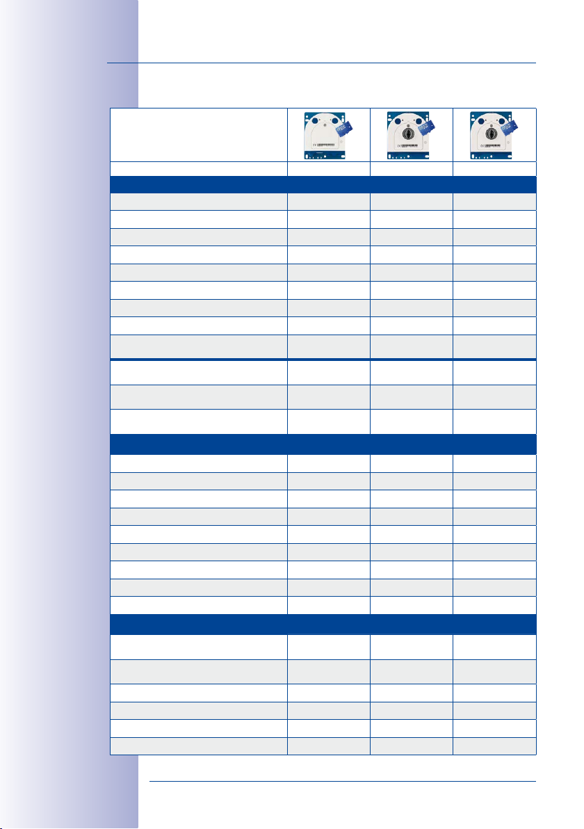
1.2.4 Camera Variants– Lenses, Hardware, Image Formats
Camera Model
S15D S15M S15M-Night
Lenses with 6MP/5MP Image Sensors
L10-L12 Hemispheric • • •
L20-L23 Super Wide-Angle • – –
L22-L25 Super Wide-Angle • – –
L32-L38 Wide-Angle • – –
L43-L51 Wide-Angle • – –
L65-L76 Tele • – –
L135-L160 Tele • – –
L270-L320 Tele • – –
CSVario L24-54/L28-64
(BlockFlexMount only)
Image sensor with custom exposure
zones
Sensor sensitivity 6MP in lux at
1/60sand1s
Sensor sensitivity 5MP in lux at
1/60sand1s
Hardware Features
IP protection class IP66 IP66 IP66
Temp. Internal DVR (MB) 64 64 64
Internal DVR (MicroSD, SDXC, pre-installed) • • •
Microphone (in sensor modules)/speaker •/– –/– –/–
Passive infrared sensor (PIR) – – –
Integrated temperature sensor • • •
Shock detector • • •
Power consumption in watts (typical) < 5 < 4.5 < 4.5
Variable PoE class 2 – 3 2 – 3 2 – 3
Image Formats, Frame Rates and Image Storage
Max. resolution (per sensor)
Max. frame rate (MxPEG, max. resolution)
CIF images with 4GB MicroSD DVR 250,000 250,000 250,000
VGA images with 4GB MicroSD DVR 125,000 125,000 125,000
MEGA images with 4GB MicroSD DVR 40,000 40,000 40,000
QXGA images with 4GB MicroSD DVR 20,000 20,000 20,000
• – –
Color/BW
(freely combinable)
0.1/0.005 and
0.02/0.001
0.25/0.013 and
0.05/0.0025
6MP (3072x2048)
5MP (2592x1944)
6MP: 8fps
5MP: 10fps
Color BW
0.1/0.005 0.02/0.001
0.25/0.013 0.05/0.0025
6MP (3072x2048)
5MP (2592x1944)
6MP: 8fps
5MP: 10fps
6MP (3072x2048)
5MP (2592x1944)
6MP: 8fps
5MP: 10fps
© MOBOTIX AG • Security-Vision-Systems • Made in Germany
www.mobotix.com • sales@mobotix.com
Page 29
Technical Specifications
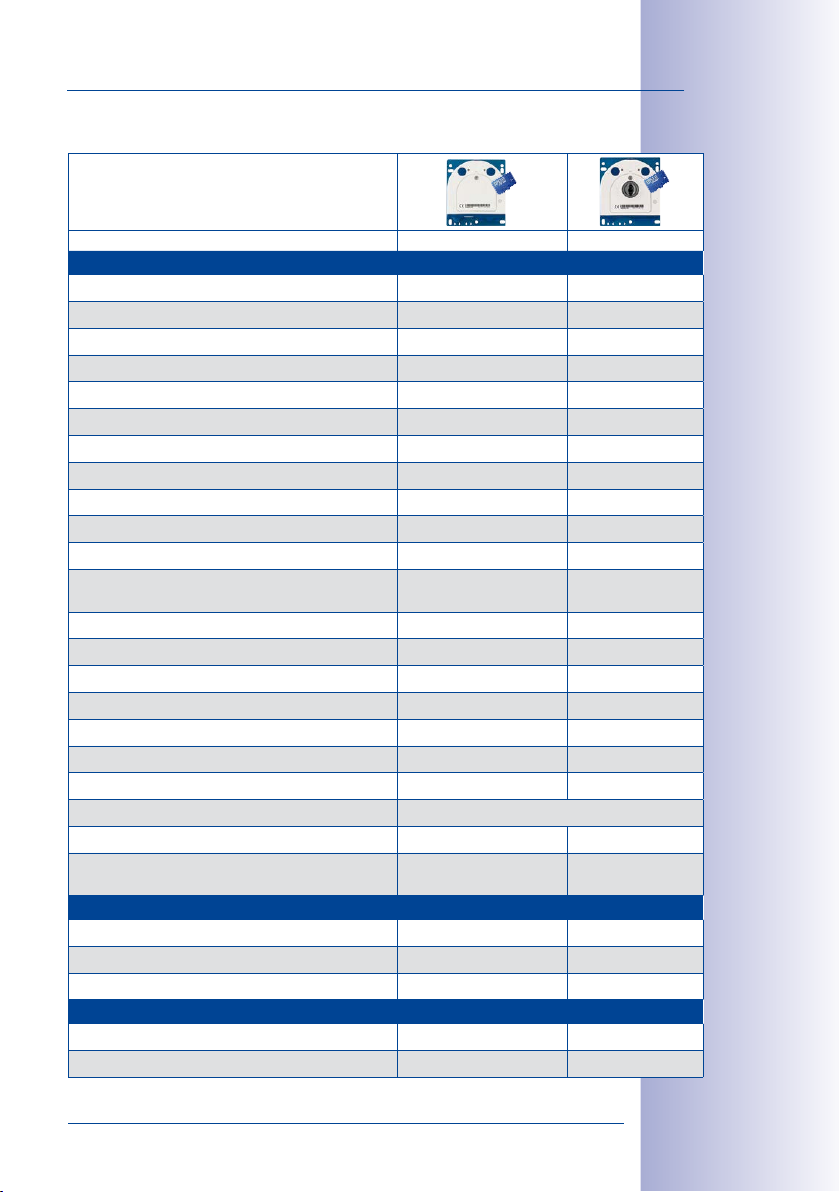
1.2.5 Camera Variants– Software Features
Camera Model
S15D S15M
General Features
Digital zoom (continuous) with panning • •
Motion JPEG/MxPEG codecs •/• •/•
Programmable exposure ones • (not for thermal sensors) •
Alarms when exceeding/dropping below spec. temp.. (MX-SM-TR only) –
Snapshot rec. (pre-/post-alarm images) 50 50
Terabyte ring buer storage (internal/network) • •
Continuous rec. with sound (0.2 to 30fps) • •
Event recording with sound • •
Time and event control • •
Weekly schedules/holidays • •
Web functionality (FTP, email) • •
Playback/Quad and MultiView, bidirectional sound in
browser
Logo generator, animated • •
Flexible event logic • •
Master/Slave arming • •
Several scheduled privacy zones • •
Customized voice messages • •
VoIP telephony (audio/video, alert) • •
Remote alarm notification (network msg.) • •
Signal inputs/outputs, RS232 Via MX-Input-Box/MX-Output-Box, MX-232-IO-Box
Programming interface/HTTP API • •
Security features (HTTPS/SSL, IP-based access control,
IEEE 802.1X network authentication)
Video Analysis
Video Motion detector • •
MxAnalytics – –
MxActivitySensor • •
Video Management Software
MxManagementCenter • •
MOBOTIX App • •
• •
• •
29/156
Free-of-charge
download from
www.mobotix.com
or App Store
© MOBOTIX AG • Security-Vision-Systems • Made in Germany
www.mobotix.com • sales@mobotix.com
Page 30
30/156
Functionality depends on
camera variant
(see
Section 1.2.5,
«Camera Variants –
Software Features»
)!
S15 Camera Manual: Product Overview
1.2.6 Technical Data
Technical Data S15
Model variants
(fitted with day or nicht sensors)
Lens options 10 to 270mm 35mm, hor. angle of view 180° to 8° (6MP)
Sensitivity Color sensor (6MP): 0.1Lux at 1/60s, 0.005Lux at 1s
Image sensors 1/1.8“ CMOS, 6MP, Progressive Scan
Max. image resolution Color: 3072x2048 (6MP), 6144x2048 (12MP)
Image formats
(per sensor)
Max. frame rate M-JPEG
(live/recording)
Max. frame rate MxPEG
(live and recording including
sound)
Image compression MxPEG, M-JPEG, JPEG
Internal DVR MicroSD card pre-installed (SDXC)
External
video ring buer
Software (included) MxManagementCenter video management software,
Image processing
Virtual PTZ Digital pan/tilt/zoom, continuous 8X zoom
Alarm/events Video Motion detection, MxActivitySensor, external signal,
Microphone and speaker S15D: Microphone integrated into optical and
Audio features Lip-synchronous audio, two-way communication, audio
MX-S15M
(day),
MX-S15M-NIGHT
MX-S15D (any combination of day/night/Thermal/Thermal-TR
sensor modules)
12 to 320mm 35mm, hor. angle of view 180° to 7° (5MP)
B&W sensor (6MP): 0.02Lux at 1/60s, 0.001Lux at 1/1s
1/2.5“ CMOS, 5MP, Progressive Scan
Black and white: 3072x2048 (6MP), 6144x2048 (12MP)
3072x2048 (6MP), 2592x1944 (5MP),
1920x1080 (Full HD),
1024x768, 800x600, 768x576 (D1-PAL),
640x480, 384x288, 320x240, 160x120, custom image
formats
VGA: 30fps, MEGA: 15fps, QXGA: 8fps, 6MP: 4fps
Dual image: 12MP 2fps, 10MP 3fps
VGA: 30fps, MEGA: 30fps, QXGA: 20fps, 6MP: 8fps, 5MP:
10fps,
Dual image: 12MP 4fps, 10MP 5fps
Directly on NAS and computer/server without additional
recording software
MOBOTIX App for iOS devices with iOS 5.0 and higher
Backlight compensation, automatic white balance, image
distortion correction, panorama correction,
detection, MxActivitySensor,
temperature sensor, PIR, microphone, shock detector,
notification over e-mail, FTP, IP telephony (VoIP, SIP), visual/
acoustic alarm, pre- and post-alarm images
BlockFlexMount sensor modules; external microphone and
speaker can be connected,
S15M: external microphone and speaker can be connected
recording
2048x1536 (QXGA),
1280x960 (MEGA), 1280x720 (HD),
704x576(TV-PAL),
Video Motion
© MOBOTIX AG • Security-Vision-Systems • Made in Germany
www.mobotix.com • sales@mobotix.com
Page 31

Technical Specifications
Technical Data S15
Interfaces
Video telephony VoIP/SIP, two-way communication, remote controlling with
Security User/group management, HTTPS/SSL, IP address filter, IEEE
Certifications EMC (EN55022, CISPR22, EN55024, EN61000-6-1/2,
Power supply Year-round Power-over-Ethernet (IEEE 802.3af); variable PoE
Power consumption S15D: Typical <4.5W with 1sensor module, <5W with
Operating Conditions IP66, –30 to +60 °C/–22 to +140 °F,
Protection against mechanical
impact
Dimensions/weight S15M
Dimensions/weight S15D
Dimensions/weights
Sensor modules
Weight of 2m connection cable
(per sensor module, S15D only)
Delivered parts Housing (high-resistance composite, PBT), white, blue
10/100 Ethernet (patch or installation cable), MiniUSB, MxBus;
inputs and outputs and RS232 via accessories; external
microphone, external speaker
key code, event notification
802.1x, intrusion detection, digital image signature
FCCpart15B, CFR47, AS/NZS3548)
class, approx. 5W (S15D)/4.5W (S15M)
2sensor modules
S15M: Typical <4.5W
air humidity up to 90–100% (acc. to EN50155 Chap. 12.2.5)
IK06
(according to IEC62262/EN50102)
W x H x D: 115 x 130 x 40mm (installation dimensions); weight:
approx. 457g (including lens)
W x H x D: 115 x 130 x 33mm; weight: approx. 444g (without
sensor modules, see below)
L10-L12: diam. x D: 43 x 45mm (installation dim.), weight: 85g
L22-
L25, L43-L51: diam. x D: 43 x 57mm (installation dim.),
weight: 111g
L32-
L35, L65-L76, L135-L160: diam. x D: 43 x 60mm (installation dim.), weight: 122g
L270-L320: diam. x D: 43 x 60mm (installation dim.), weight:
160g
about 68g
anodized aluminum base plate, shock-resistant dome for
sensor module L10-L12, coated glass pane for all other
sensor modules, mounting parts, Allen wrench, 50cm patch
cable, manual, software, MicroSD card pre-installed (SDXC))
31/156
© MOBOTIX AG • Security-Vision-Systems • Made in Germany
www.mobotix.com • sales@mobotix.com
Page 32

32/156
S15 Camera Manual: Product Overview
Technical Specifications Thermal Sensor Module/Thermal-TR Sensor Module
Lens Options Thermal Sensor Module: L43 (45°), L65 (25°), L135 (17°)
Sensitivity NETD typ. 50mK (equals 0.05°C), <79mK
Image Sensor Uncooled microbolometer, 336x252 pixels, spectral range 7.5
Temperature
Measurement Range
Max. Image Size Can be scaled up to 3072x2048 (6MP), dual images are automati-
Max. Frame Rate 9fps (when displaying an optical sensor module and a thermal
Software Features O-color/black & white image display, mirrored image, obscured
Power Consumption Typ. 1.5W per Thermal Sensor Module
Operating Conditions IP66 (DIN EN 60529)
Dimensions Total length: 78mm, max. Ø: 63mm
Materials Module housing: Aluminum, black anodized;
Weight <330g (one Thermal Sensor Module without sensor cable)
Thermal-TR Sensor Module: TR079 (45°), TR119 (25°), TR237 (17°)
(horizontal angle of view)
to 13.5μm
–40 bis +550 °C (temperature of the displayable objects)
precision of Thermal-TR Sensor Module: ±10K of the thermal
radiation measured at the sensor
cally scaled to size of the optical sensor module
sensor module, the overall frame rate of the camera is reduced
to 9fps)
image areas, vPTZ (virtual pan/tilt/zoom), text and logo display,
display of event/action symbols, meter display (bar chart or
diagram), temperature control windows
–30 to +60 °C/–22 to +140 °F (DIN EN 50155)
Pressure plate: Stainless steel V2A
Technical Data S15D with Thermal Sensor Module/Thermal-TR Sensor Module
Image Formats
(per sensor)
Alarm/Events Video Motion detection, MxActivitySensor, external signals, shock
Operating Conditions IP65 (DIN EN 60529)
Power Consumption Depending on sensor modules used:
Max. Power Consumption of
Attached Extension Modules
Power Supply Power-over-Ethernet (IEEE 802.3af);
Standard formats like Full HD, VGA, etc. up to 3072x2048 (5MP)
and custom formats
detector, notification via e-mail, FTP, pre- and post-alarm images
–30 to +60 °C/–22 to +140 °F (DIN EN 50155)
• 1 thermal, 1 optical: typ. 6.5W (briefly up to 7.5W possible)
• 2 thermal: typ. 7W (briefly up to 8W possible)
• 1 thermal: typ. 5.5W (briefly up to 6.5W possible)
USB only: ≤1W
MxBus only: ≤1W
USB and MxBus: ≤2W
PoE Class3 required
© MOBOTIX AG • Security-Vision-Systems • Made in Germany
www.mobotix.com • sales@mobotix.com
Page 33

Technical Specifications
MOBOTIX S15D with 2 MX-SM-Thermal/MX-SM-TR
MOBOTIX S15D with 1MX-SM-Thermal/MX-SM-TR, 1MX-SM-D12
33/156
© MOBOTIX AG • Security-Vision-Systems • Made in Germany
www.mobotix.com • sales@mobotix.com
Page 34

34/156
S15 Camera Manual: Product Overview
1.3 Delivered Parts and Dimensions
go to Products > S15
FlexMount and open the
basket. It contains a
Product Congurator.
Use this to order the
required parts in any of
the available colors.
1.3.1 S15D Core (Base Module)On www.mobotix.com
1.11
1.1
1.2
1.4
1.3
1.5
1.6
1.9
1.10
1.7
1.8
M.6
M.7
M.5
M.4
M.8
M.3
M.2
M.1
M.9
M.10
© MOBOTIX AG • Security-Vision-Systems • Made in Germany
www.mobotix.com • sales@mobotix.com
Page 35

Delivered Parts and Dimensions
Item Number Part Name
1.1 1 S15D Core (base module with base plate)
1.2 1 Housing cover for S15D (installed)
1.3 1 Stainless steel flat-head Allen screw M4x8 (installed)
1.4 1 Washer (installed)
1.5 3 Sealing plug, blue, small (sensor modules, USB, inserted)
1.6 1 Sealing plug, blue, large (Ethernet patch cable, installed)
1.7 1 Cable retainer with bayonet catch (Ethernet patch cable,
1.8 1 Single wire plug, white (Ethernet installation cable, microphone,
1.9 1 MicroSD card pre-installed (SDXC)
1.10 1 Rotary plug, SD card, blue (installed)
1.11 1 Ethernet patch cable, 50cm, with seal
Mounting Supplies
Item Number Part Name
M.1 4 Stainless steel washers, diam. 4.3mm
M.2 4 6-mm screw anchors
M.3 4 Stainless steel wood screws 4x40mm with PZ 2 driver bit
M.4 2 Cable plug, 5–7mm, white (Ethernet installation cable)
M.5 1 Cable plug, 3–5mm, white (Ethernet installation cable)
M.6 1 Allen wrench 2.5mm
M.7 1 Lens wrench (lens, dome)
M.8 1 Module wrench (sensor module, glass/filter insert)
M.9 1 Cable tie (Ethernet installation cable, microphone, speaker,
M.10 1 Screwdriver (screw clamps)
installed)
speaker, MxBus; installed)
MxBus)
35/156
© MOBOTIX AG • Security-Vision-Systems • Made in Germany
www.mobotix.com • sales@mobotix.com
Page 36

36/156
S15 Camera Manual: Product Overview
S15D Core (Base Module) Design
The base module of the MOBOTIX S15D consists of a housing, a housing cover and a base
plate for attaching the camera.
LED default settings:
1 Power (on), Error (ashes)
2 Recording (ashes)
R
1 2
L
MicroSD card
LEDs
Base plate
Keys
S15D housing cover
Pressure compen-
Triple cable retainer
Externally-Accessible Connections on the S15D
The MOBOTIX S15D provides the following external connections that can be accessed
once the cover plugs are removed:
sation
Bayonet catch
Special USB cable for
external devices (USB
stick, USB hard drive)
available as an accessory
Cables with straight
plugs can be used for the
S15 on the camera only
Ethernet patch cable
MiniUSB
Sensor modules
For external connections shown above always use the corresponding MOBOTIX cables
with seal:
• Ethernet patch cable: MX-OPT-CBL-LAN-1/2/5/10
• MiniUSB (straight/straight): MX-CBL-MU-STR-05/2/5
• MiniUSB (straight/angled): MX-CBL-MU-EN-STR-05/2/5
• MiniUSB to USB-A (straight to USB port): MX-CBL-MU-STR-AB-05/2/5
• Sensor modules: MX-FLEX-OPT-CBL-05/1/2/3
© MOBOTIX AG • Security-Vision-Systems • Made in Germany
www.mobotix.com • sales@mobotix.com
Page 37

Delivered Parts and Dimensions
MOBOTIX patch cable
Internally-Accessible Connections on the S15D
The MOBOTIX S15D provides the following internal connections that can be accessed once
the cover plugs and housing cover are removed:
LSA+ terminal
Ethernet Installation
MxBus, microphone,
cable
Screw terminals
speaker
37/156
MOBOTIX-RJ45 or
MxBus, microphone,
Before laying the Ethernet installation cable, remove the bayonet catch and replace the
Ethernet patch cable plug with either one of the additional plugs (M.4/5) or the single wire
plug (1.8), depending on the cable used.
speaker
Additional cables
(MxBus, sound)
Ethernet installation cable
or
MxBus, microphone,
speaker
Installation cable
© MOBOTIX AG • Security-Vision-Systems • Made in Germany
www.mobotix.com • sales@mobotix.com
Page 38

38/156
S15 Camera Manual: Product Overview
The drilling templates
can be found at the
end of the manual
Always print or copy
drilling template in
their original size
S15D Core (Base Module) Dimensions
115mm/4.53in
100mm/3.94in
110mm/4.33in
100mm/3.94in
8.5mm/0.33in
Diam. 5.5mm/
13.5mm/0.53in
M6
130mm/5.12in
47.5mm/1.87in
0.22in
Attaching the Base Module
Slots
© MOBOTIX AG • Security-Vision-Systems • Made in Germany
M6 tap holes
www.mobotix.com • sales@mobotix.com
Page 39

Delivered Parts and Dimensions
33.5mm/1.32in
5mm/
0.2in
39/156
© MOBOTIX AG • Security-Vision-Systems • Made in Germany
www.mobotix.com • sales@mobotix.com
Page 40

40/156
S15 Camera Manual: Product Overview
*6MP image sensor: rst
value (L10)
5MP image sensor:
second value (L12)
Sensor module
including status LEDs
and microphone
1.3.2 Sensor Modules L10-L12*
2.6
2.5
2.1
2.2
2.3
2.4
Item Number Part Name
2.1 1 Sensor module with axed washer
2.2 1 MOBOTIX lens L10-L12 (installed)
2.3 1 Dome (installed)
2.4 1 Cable retainer with bayonet catch (installed)
2.5 1 Sealing plug, blue, small (installed)
2.6 1 Nut (plastic)
© MOBOTIX AG • Security-Vision-Systems • Made in Germany
www.mobotix.com • sales@mobotix.com
Page 41

Delivered Parts and Dimensions
Diam. 43mm/1.7in
Front View
LEDs
Sensor module
housing
Microphone
Rear View
Markers for top
Sensor cable con-
nection
Sensor module
housingl
1 2
Diam. 50mm/2in
Diam. 50mm/2in
41/156
LED default settings:
1 Power (on), Error (ashes)
2 Recording (ashes)
Top = top border of
image (North)
Pressure compen-
Side View
weight without lock ring: 85g
weight with lock ring: 91g
© MOBOTIX AG • Security-Vision-Systems • Made in Germany
sation
Sensor module
Extension
Diam. 43mm/1.7in
58mm/2.3in
30mm/1.2in
40mm/1.6in
15mm/0.6in
www.mobotix.com • sales@mobotix.com
Diam. 43mm/1.7in
Diam. 43mm/1.7in
Page 42

42/156
S15 Camera Manual: Product Overview
*6MP image sensor: rst
value
5MP image sensor: second value
Sensor module
including status LEDs
and microphone
1.3.3 Sensor Modules L20-L23, L22-L25, L32-L38, L43-L51, L65-L76, L135-L160*
3.1
3.6
3.5
3.4
3.2
3.3
Item Number Part Name
3.1 1 Sensor module with axed washer
3.2 1 MOBOTIX lens L20-L23/L22-L25/L32-L38/L43-L51/L65-L76/
3.3 1 Protective glass insert with coated glass (installed)
3.4 1 Cable retainer with bayonet catch (installed)
3.5 1 Sealing plug, blue, small (installed)
3.6 1 Nut (plastic)
L135-L160 (installed)
© MOBOTIX AG • Security-Vision-Systems • Made in Germany
www.mobotix.com • sales@mobotix.com
Page 43

Delivered Parts and Dimensions
Diam. 50mm/2in
Diam. 43mm/1.7in
48mm/1.89in
15mm/0.6in
Front View
LEDs
Sensor module
housing
Microphone
Rear View
Markers for top
1 2
Diam. 50mm/2in
43/156
LED default settings:
1 Power (on), Error (ashes)
2 Recording (ashes)
Sensor cable con-
Sensor module
Pressure compen-
Side View
weight without lock ring: 122g
weight with lock ring: 128g
Sensor module
nection
housing
sation
Extension
40mm/1.6in
Diam. 43mm/1.7in
Diam. 43mm/1.7in
Diam. 43mm/1.7in
Top = top border of
image (North)
© MOBOTIX AG • Security-Vision-Systems • Made in Germany
www.mobotix.com • sales@mobotix.com
Page 44

44/156
S15 Camera Manual: Product Overview
*6MP image sensor: rst
value
5MP image sensor: second value
Sensor module
1.3.4 Sensor Modules L270-L320*
4.6
4.5
4.1
4.2
4.3
4.4
Item Number Part Name
4.1 1 Sensor module with axed washer
4.2 1 MOBOTIX lens L270-L320 (installed)
4.3 1 Protective lens cover (installed)
4.4 1 Cable retainer with bayonet catch (installed)
4.5 1 Sealing plug, blue, small (installed)
4.6 1 Nut (plastic)
© MOBOTIX AG • Security-Vision-Systems • Made in Germany
www.mobotix.com • sales@mobotix.com
Page 45

Delivered Parts and Dimensions
Diam. 50mm/2in
Diam. 43mm/1.7in
48mm/1.89in32mm/1.26in
15mm/0.6in
Front View
Protective lens cover
Sensor module
housing
Rear View
Markers for top
45/156
Diam. 50mm/2in
Sensor cable con-
Sensor module
Pressure compen-
Side View
weight without lock ring: 122g
weight with lock ring: 128g
Sensor module
Extension
nection
housing
sation
Top = top border of
image (North)
Diam. 43mm/1.7in
40mm/1.6in
Diam. 43mm/1.7in
Diam. 43mm/1.7in
© MOBOTIX AG • Security-Vision-Systems • Made in Germany
www.mobotix.com • sales@mobotix.com
Page 46

46/156
S15 Camera Manual: Product Overview
*6MP image sensor: rst
value
5MP image sensor: second value
BlockFlexMount
including status LEDs
and microphone
1.3.5 BlockFlexMounts L10-L12, L20-L23, L22-L25, L32-L38, L43-L51, L65-L76, L135-L160, L270-L320*
5.1
5.4 5.2
5.3
Item Count Part Name
5.1 1 Housing MX-BFM-MX, black anodized
5.2 1 MOBOTIX lens L10 to L270 (6MP), L12 to L320 (5MP) (installed)
5.3 1 Cable lock with bayonet catch (installed)
5.4 1 Sealing plug blue, small (installed)
© MOBOTIX AG • Security-Vision-Systems • Made in Germany
www.mobotix.com • sales@mobotix.com
Page 47

Delivered Parts and Dimensions
Front View
47/156
Back View
Side View
4 holes 4.2mm diam.
Status LEDs
Microphone
Arrows indicate
Connector for sensor
2 tap holes/side
top
cable
Pressure vent
M4x5mm
Lens
D
32mm/1.26in
32mm/1.26in
40mm/1.57in
8mmL
25mm/0.98in
40mm/1.57in
40mm/1.57in
40mm/1.57in
22mm/0.87in
Top = upper image border (North direction)
Measurements
dep. on Lens
Lens D L
L10-L12
23.5mm/
0.93in
L20-L23
22.0mm/
0.87in
L22-L25
22.0mm/
0.87in
L32-L38
22.0mm/
0.87in
L43-L51
20.0mm/
0.79in
L65-L76
22.0mm/
L135-L160
L270-L320
0.87in
22.3mm/
0.88in
27.0mm/
1.06in
13.0mm/
0.51in
17.0mm/
0.67in
17.0mm/
0.67in
18.2mm/
0.72in
11.7mm/
0.46in
17.5mm/
0.69in
17.8mm/
0.70in
42.5mm/
1.67in
© MOBOTIX AG • Security-Vision-Systems • Made in Germany
www.mobotix.com • sales@mobotix.com
Page 48

48/156
S15 Camera Manual: Product Overview
1.3.6 BlockFlexMount CS Mount
6.1
BlockFlexMount
including microphone
*6MP image sensor: rst
value (L24-54)
5MP image sensor:
second value (L28-64)
MX-OPTCS-L24-54/L28-64* lens
needs to be ordered separately!
6.4
6.3
Item Count Part Name
6.1 1 Housing MX-BFM-CS, black anodized
6.2 2 Spacer disc 0.25mm thick
6.3 1 Cable lock with bayonet catch (installed)
6.4 1 Sealing plug blue, small (installed)
6.2
© MOBOTIX AG • Security-Vision-Systems • Made in Germany
www.mobotix.com • sales@mobotix.com
Page 49

Delivered Parts and Dimensions
Front View
49/156
Back View
Top View
4 holes 4.2mm diam.
Arrows indicate
Connector for sensor
Pressure vent
Lock screw (Allen
wrench 1.5mm)
Microphone
top
cable
32mm/1.26in
32mm/1.26in
40mm/1.57in
8mm/0.31in43.4mm/1.71in
40mm/1.57in
40mm/1.57in
Top = upper image border (North direction)
Dia.34mm/1.34in
Lens (needs to be ordered
separately)
2 tap holes/side
M4x5mm
22.5mm/0.89in
37.6mm/1.48in
© MOBOTIX AG • Security-Vision-Systems • Made in Germany
www.mobotix.com • sales@mobotix.com
22mm/0.87in
Page 50

50/156
S15 Camera Manual: Product Overview
1.3.7 Sensor Modules Thermal L43, L65, L135 and Thermal-TR079/119/237
7.1
7.8
7.7
7.6
7.5
Item Count Part Name
7.1 1 Housing MX-SM-Thermal-L43/65/135 or
MX-SM-TR079/119/237, black anodized
7.2 1 Front plate aluminum, black anodized (installed)
7.3 1 Pressure plate Ø63mm, stainless steel (installed)
7.4 3 Cylinder head screws M4x50mm, stainless steel (installed)
7.5 1 Cable lock, blue (installed)
7.6 1 Sealing plug blue, small (installed)
7.7 1 Allen wrench 3mm
7.8 1 Special export regulations German/English
7.2
7.3
7.4
© MOBOTIX AG • Security-Vision-Systems • Made in Germany
www.mobotix.com • sales@mobotix.com
Page 51

Delivered Parts and Dimensions
12.5mm/0.49in
17mm/0.67in
Front View
Pressure plate dia.
63mm/2.48in
(behind wall/faceplate)
Front plate dia.
57mm/2.24in
(visible)
Back View
51/156
Ø 63mm/2.48in
Ø 57mm/2.44in
Side View
Arrows indicate
Connector for sensor
3 cylinder head
Thickness 0 to
14mm/0.55in
3 cylinder head screws
Hole diameter
48mm/1.89in
Ø M4, length of thread
top
cable
Pressure vent
screws
M4x50mm
4mm/0.16in
3.5mm/0.14in
78mm/3.07in
Dia. 60mm/2.36in
Top = upper image border (North direction)
© MOBOTIX AG • Security-Vision-Systems • Made in Germany
www.mobotix.com • sales@mobotix.com
Page 52

52/156
S15 Camera Manual: Product Overview
On www.mobotix.com
got to Products > S15
FlexMount and open the
basket. It contains the
Product Congurator,
Use this to order the
required parts in any of
the available colors.
1.3.8 S15M
M.7
M.6
M.5
M.4
M.3
M.2
M.1
M.9
M.10
8.13
8.1
8.2
8.3
8.4
8.6
8.5
8.7
8.8
8.10
8.11
8.12
8.9
© MOBOTIX AG • Security-Vision-Systems • Made in Germany
www.mobotix.com • sales@mobotix.com
Page 53

Delivered Parts and Dimensions
Item Number Part Name
8.1 1 Camera housing (with base plate)
8.2 1 Lens L10 (6MP)/L12 (5MP) (installed)
8.3 1 Dome (installed)
8.4 1 Housing cover for S15M (installed)
8.5 3 Stainless steel flat-head Allen screw M4x8 (installed)
8.6 1 Washer
8.7 1 Sealing plug, blue, small (sensor modules, USB, inserted)
8.8 1 Sealing plug, blue, large (Ethernet patch cable, installed)
8.9 1 Cable retainer with bayonet catch (Ethernet patch cable,
8.10 1 Single wire plug, white (Ethernet installation cable, microphone,
8.11 1 MicroSD card pre-installed (SDXC)
8.12 1 Rotary plug, SD card, blue (installed)
8.13 1 Ethernet patch cable, 50cm, with seal
Mounting Supplies
Item Number Part Name
M.1 4 Stainless steel washers, diam. 4.3mm
M.2 4 6-mm screw anchors
M.3 4 Stainless steel wood screws 4x40mm with PZ2 driver bit
M.4 2 Cable plug, 5-7mm, white (Ethernet installation cable)
M.5 1 Cable plug, 3-5mm, white (Ethernet installation cable)
M.6 1 Allen wrench 2.5mm
M.7 1 Lens wrench (lens, dome)
M.9 1 Cable tie (Ethernet installation cable, microphone, speaker,
M.10 1 Screwdriver (screw clamps)
installed)
speaker, MxBus)
MxBus)
53/156
© MOBOTIX AG • Security-Vision-Systems • Made in Germany
www.mobotix.com • sales@mobotix.com
Page 54

54/156
S15 Camera Manual: Product Overview
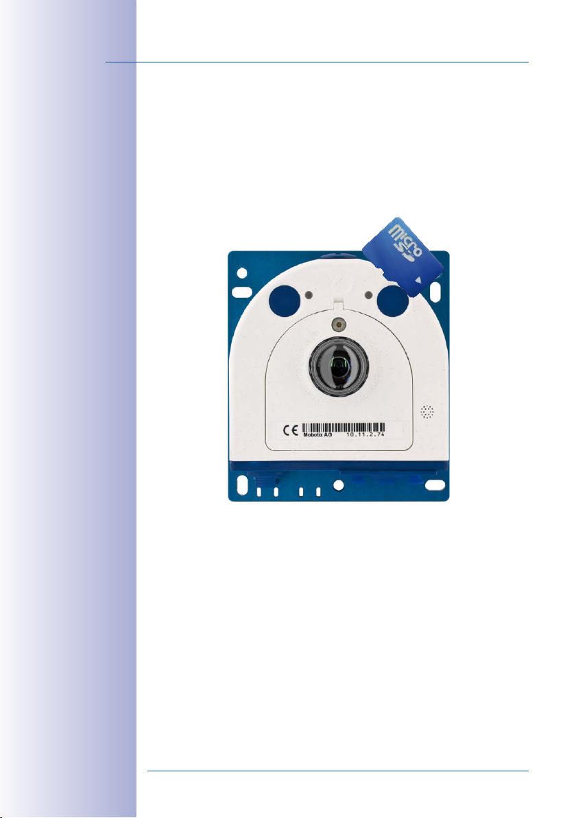
S15M Camera Housing
The MOBOTIX S15M consists of a base plate for attaching the camera, a housing with
built-in lens, and a housing cover.
LED default settings:
1 Power (on), Error (ashes)
2 Recording (ashes)
MicroSD Card
LEDs
Base plate
Keys
Lens with dome
S15Mhousing cover
Pressure compen-
Triple cable retainer
Externally-Accessible Connections on the S15M
The MOBOTIX S15M provides the following external connections that can be accessed
once the cover plugs are removed:
Ethernet patch cable
sations
Bayonet catch
MiniUSB
1 2
R L
Cables with straight
plugs can be used for the
S15 on the camera only
The external connections may only be used with the designated sealed MOBOTIX cables
(MX-OPT-CBL-LAN-1/2/5/10 Ethernet patch cable and MX-MX-CBL_MU_STR-5 MiniUSB
cable).
© MOBOTIX AG • Security-Vision-Systems • Made in Germany
www.mobotix.com • sales@mobotix.com
Page 55

Delivered Parts and Dimensions
MOBOTIX patch cable
Internally-Accessible Connections on the S15M
The MOBOTIX S15M provides the following internal connections that can be accessed once
the cover plugs and housing cover are removed:
LSA+ terminal
Ethernet installation
MxBus, microphone,
cable
Screw terminals
speaker
55/156
MOBOTIX-RJ45 or
MxBus, microphone,
Before laying the Ethernet installation cable, remove the bayonet catch and replace the
Ethernet patch cable plug with either one of the additional plugs (M.4/5) or the single wire
plug (2.10), depending on the cable used.
© MOBOTIX AG • Security-Vision-Systems • Made in Germany
www.mobotix.com • sales@mobotix.com
speaker
Ethernet installation cable
or
MxBus, microphone,
speaker
Additional cables
(MxBus, sound)
Installation cable
Page 56

56/156
S15 Camera Manual: Product Overview
The drilling templates
can be found at the
end of the manual
Always print or copy
drilling template in
their original size
Dimensions S15M
110mm/4.33in
100mm/3.94in
8.5mm/0.33in
Attaching the Camera Housing
115mm/4.53in
100mm/3.94in
Diam. 5.5mm/
13.5mm/0.53in
M6
130mm/5.12in
47.5mm/1.87in
0.22in
Slots
M6 threaded holes
© MOBOTIX AG • Security-Vision-Systems • Made in Germany
www.mobotix.com • sales@mobotix.com
Page 57

Delivered Parts and Dimensions
48mm/1.89in
39.5mm/1.56in
33.5mm/1.32in
57/156
5mm/
0.2in
© MOBOTIX AG • Security-Vision-Systems • Made in Germany
www.mobotix.com • sales@mobotix.com
Page 58

58/156
S15 Camera Manual: Product Overview
1.4 Available Accessories
1.4.1 Extension for Sensor Module
Order No.: MX-S15-OPT-MK-EX
Each of these extensions increases the installation depth by 40mm. They can be mounted
directly onto the sensor modules themselves or onto existing extensions.
1.4.2 Ceiling/Wall Installation Set
Order No.: MX-S15-OPT-MK-CW
This set contains everything that is needed to attach a
sensor module to a ceiling or wall using 15° wedges:
One extension (MX-S15-OPT-MK-EX), two 15° wedges
(white, black), two wedge washers and an additional
nut.
Out of the colored wedges, use the most suitably-colored
wedge for the visible area and the other one for inserting on the rear.
1.4.3 Connection Cable for Sensor Module
Order No.: MX-FLEX-OPT-CBL-05/1/2/3
Do not bend the
sensor cables
Cables with straight
plugs can be used for the
S15 on the camera only
This cable, which is up to three meters long (three
meters only allowed for 6MP and Thermal image sen
sors), connects one sensor module to the S15D. The
seals integrated into the cable combine with the bayonet
catch on the sensor module and the sealed port of the
S15D to provide IP66-compliant weatherproofing. Also
included are two hinged ferrites that are attached at a
distance of 10cm to the base module and the sensor
module after installation.
-
1.4.4 MiniUSB Cable to MiniUSB (Straight/Straight or Straight/Angled)
Order No.: MX-CBL-MU-STR-05/2/5 (Straight/Straight)
Order No.: MX-CBL-MU-EN-STR-05/2/5 (Straight/Angled)
With this cable, which is up to five meters long, MOBOTIX
add-on modules (MX-232-IO-Box, ExtIO, CamIO) can be
connected directly to the S15.
© MOBOTIX AG • Security-Vision-Systems • Made in Germany
www.mobotix.com • sales@mobotix.com
Page 59

Available Accessories
1.4.5 MiniUSB Cable to USB a Socket
Order No.: MX-CBL-MU-STR-AB-05/2/5
USB-based storage media (for example, USB hard drives)
can be connected directly to the S15 with this cable,
which is up to five meters long.
1.4.6 Ethernet Patch Cable for Bayonet Catch
Order No.: MX-OPT-CBL-LAN-1/2/5/10
(length 1m/2m/5m/10m)
The MOBOTIX-developed special cable can be installed
in a waterproof manner and has an integrated sealing gasket. Every S15 ships with a 0.5-m-long cable as
standard, which can be exchanged for a patch cable
up to 10m in length.
1.4.7 NPA-PoE-Set
Order No.: MX-NPA-PoE-EU u. MX-NPA-PoE-INT (Version EU and Version INT)
Order No.: MX-CBL-NPA-BAT-2 (battery cable for mobile voltage sources)
This is a multifunctional PoE injector according to the
IEEE 802.3af standard – with three connectors (for
network, camera/PoE device, PC), universal power
supply unit with interchangeable adapter plugs and
crossover function. The NPA-PoE-Set connects and
remotely supplies an S15 with power via an Ethernet
cable up to 100m in length. The blue adapter can
also be connected to mobile voltage sources from
12 to 42V DC by means of an additionally available
battery cable. The “EU” version of the NPA-PoE-Set is
supplied as standard with a European adapter, while
the “INT” version includes four adapters (EU, USA, UK, AUS).
59/156
1.4.8 MX-Overvoltage-Protection-Box
Order no.: MX-Overvoltage-Protection-Box-RJ45
Order no.: MX-Overvoltage-Protection-Box-LSA
Weatherproof network connector (protection class IP65,
–30 bis +60 °C)
MOBOTIX IP cameras
At the same time, the MX-Overvoltage-Protection-Box
© MOBOTIX AG • Security-Vision-Systems • Made in Germany
www.mobotix.com • sales@mobotix.com
with surge protection of up to 4kV for
, ideal for replacing the MX-Patch-Box.
Page 60

60/156
S15 Camera Manual: Product Overview
provides a weatherproof connection of a camera’s patch cable to a network patch cable
-RJ45
variant) or a network installation cable (
(
1.4.9 MX-NPA-Box
Order No.: MX-OPT-NPA1-EXT
The MX-NPA-Box is a weatherproof PoE injector conforming
to the IEEE 802.3af standard and is designed to connect to a
MOBOTIX camera external voltage sources (12 to 57V DC).
The MX-NPA-Box is equipped with the weatherproof
and extremely compact exterior housing of the PatchBox (protection class IP66, –30 to +60°C/–22 to +140°F,
which means it can also be installed in the space of the
Outdoor Wall Mount. MX-NPA-Box interfaces: Camera
via patch cable, Ethernet via LSA+ and external power
supply (12 to 57V DC is possible).
1.4.10 MX-GPS-Box
Order No.: MX-OPT-GPS1-EXT
This box primarily serves as a high-precision time source
for systems without an Internet connection. The IT and
Secure models additionally provide triggering of GPS-based
events (reaching or moving away from a specified position; exceeding or not reaching a specified speed). The
MX-GPS-Box can be connected as an add-on module to
all MOBOTIX cameras with an MxBus interface.
-LSA
variant).
The MX-GPS-Box has the same compact exterior housing as the MX-Patch-Box and the
MX-NPA-Box (IP66 protection class, –30 to +60°C/–22 to +120°F. Note that this box should
not be installed below other wall-mounted units. It should be installed on the exterior of
the building with a large section of open sky above it, which ensures the best possible
reception from GPS satellites and thereby the highest possible accuracy of the received
GPS data. The maximum length of the MxBus cable (diameter: 0.8mm) is 50m.
1.4.11 MX-232-IO-Box
Order No.: MX-OPT-RS1-EXT
This box provides the signal inputs and outputs as well as
the RS232 (serial) interface. It replaces the connections that
were handled on the older camera models via a D-Sub
15-HD connector. The MX-232-IO-Box can be connected
as an add-on module to all MOBOTIX cameras with an
MxBus or USB interface. The maximum length of the MxBus cable (diameter: 0.8mm) is
50m. If the MiniUSB connection is used, the maximum cable length is 5m.
© MOBOTIX AG • Security-Vision-Systems • Made in Germany
www.mobotix.com • sales@mobotix.com
Page 61

Available Accessories
1.4.12 ExtIO Expansion Module
Order No.: MX-ExtIO
The device, which is suitable both for on-wall and in-wall
installations, contains a powerful speaker, microphone,
infrared motion sensor, ambient temperature sensor, two
input and two output contacts and two illuminated keys. It
is ideal for door communication, elevators, access control
systems, etc. The ExtIO is suitable for use as direct connection to the S15 via a MiniUSB cable (max. 5m), which
can be ordered separately, or as a network connection
via the PoE switch.
1.4.13 Mx2wire+ Media Converter
Order No.: MX-2wirePlus-Set-PW
The Mx2wire+ system allows an Ethernet network with PoE
to be set up via two-wire cables, which saves users from
having to lay several hundred meters of Ethernet cable.
For example, an existing two-wire cable of an analog
video camera can be reused to connect a high-resolution
and modern IP network camera. Mx2wire+ is delivered
in the standard wall outlet frame in dierent designs;
however, it can also be used with the available on-wall
socket that is included.
61/156
1.4.14 AudioMount
Order no.: MX-FLEX-OPT-AM-BL
The AudioMount is an installation option for the S15M with
a self-adhesive front that can be attached to the back of
thin and smooth surfaces (stainless steel plate, mailbox,
etc.). The AudioMount has a pre-installed speaker and
microphone, thus ensuring full intercom capabilities of
the camera. Together with the AudioMount and additional
MOBOTIX accessories, you can easily set up the S15M
FlexMount as a hemispherical door station (note that the
camera needs to run a firmware 4.1.9 or higher).
© MOBOTIX AG • Security-Vision-Systems • Made in Germany
www.mobotix.com • sales@mobotix.com
Page 62

62/156
S15 Camera Manual: Product Overview
1.4.15 DualMount
Order no.: MX-OPT-FM-PW
The DualMount provides for installing two sensor modules
side-by-side with parallel lines of sight, making it the ideal
installation solution for the S15D in day/night settings (both
lenses are monitoring the same area). The DualMount is
quickly and easily installed, it can be used with all avail
able sensor modules and the lenses are tilted downwards
by 25 degrees. In outdoor applications, this installation
option can be installed without drawing much attention
(beneath eaves, protruding construction elements, bridges, etc.).
1.4.16 SurroundMount
Order no.: MX-OPT-SM-PW
-
When dealing with long and narrow spaces (buses, air
planes, trains, etc.), this installation option allows positioning two hemispherical sensor modules pointing in
opposite directions. The resulting dual hemispheric image
with up to 10megapixels displays a much higher degree
of detail than a camera with only one hemispheric lens. To
better support these types of installation, MOBOTIX oers
the SurroundMount installation option for the S15D. Since
both sensor modules are tilted downwards by 25 degrees,
the resulting images cover the entire area without any blind spots.
Note that you can use the SurroundMount only with L10-L12, L22-L25 and L43-L51 sensor
modules (day or night variants).
1.4.17 HaloMount
Order no.: MX-HALO-EXT-CM/CO/NG/PW/SW
The HaloMount is the perfect installation option to install
sensor modules in rooms with in-ceiling lights. Using the
same type of fixtures as in-ceiling lights (QR-CBC/MR 16
LED Sharp Array 4/6W), this mount comes in five dierent
colors (matt chrome, chrome, brushed Nickel, white, black).
Since the inner ring can be tilted by up to 20 degrees, you
can point the sensor module (and thus, the center of the
image) to the center of the area that is to be monitored.
The HaloMount has not been designed to be used in outdoor applications. Materials:
Steel, inner ring brass; surface powder-coated or galvanized; installation diameter:
68mm/2.7in.
-
© MOBOTIX AG • Security-Vision-Systems • Made in Germany
www.mobotix.com • sales@mobotix.com
Page 63

Available Accessories
1.4.18 SpeakerMount
Order no.: MX-HALO-SP-PW/CM
The SpeakerMount, available from MOBOTIX in white or
matt chrome, is an external speaker that can be directly
connected to the S15D/S15M (no additional power supply
required). The high-quality speaker is especially suitable
for S15 cameras. The speaker is pre-installed in the
20-degree-tilting mechanism of the HaloMount and is
fitted in the same way in fake ceilings and walls. The
SpeakerMount has not been designed to be used in outdoor applications. Temperature
range: 0 to +60°C/32 to 140°F; protection class: IP20; nominal/music output: 3/4W; impedance: 8Ohms; material of the speaker: metal with perforated steel cover; connection type:
two-wire strand with luster terminal; installation diameter: 68mm/2.7in.
1.4.19 PTMount
Order no.: MX-PTMount-OPT-PW
MOBOTIX oers the high-quality, weatherproof PTMount,
an attractive, compact, discreet, and dome-shaped accessory mount that holds a single sensor module and is
adjustable in three directions. The maximum flexibility for
adjusting the modules means that you can always find
the right position. When mounted to a wall, for example,
the mount enables you to compensate for sideway tilt and
to re-align the image horizon horizontally to record the
best possible image of the surveillance area.
63/156
1.4.20 PTMount-Thermal(-TR)
Order no.: MX-SM-PTMount-Thermal-PW/BL
Order no.: MX-MT-PT-TR
This variant of the PTMount contains a thermal sensor module that is integrated into the PTMount housing (available
in white or black). Equipped with the same thermal sensors
as the thermal sensor modules, this device generates
thermal images even in complete darkness.
Using the
ant, the camera can trigger alarms when the temperature
exceeds or drops below the specified temperature.
© MOBOTIX AG • Security-Vision-Systems • Made in Germany
www.mobotix.com • sales@mobotix.com
MX-MT-PT-TR (TR
= Thermal Radiometry) vari-
Page 64

64/156
S15 Camera Manual: Product Overview
1.4.21 Sealing Ring as Dome Replacement for Sensor Modules L10-L12
Order no.: MX-OPT-Ring-L10-L12-PW/BL
For special scenarios with hemispheric sensor modules,
e.g., if light entering from the side creates reflections within
the dome, you can use the sealing ring instead of the dome
(see also
Section 3.3.3, «Replacing the Dome Against the
).
Sealing Ring (Only Sensor Modules L10-L12)»
avoid burns by the hot lens, the dome must not be removed if the sensor module is
within the reach of persons!
1.4.22 Other Accessories
Since the range of accessories for the MOBOTIX system keeps growing, you should visit
the MOBOTIX website www.mobotix.com in the Products> Accessories section to see
the entire list of available accessories.
THE MOBOTIX INFORMATION CHANNELS
In order to
MOBOTIX
© MOBOTIX AG • Security-Vision-Systems • Made in Germany
Support on the MOBOTIX Website
www.mobotix.com/other/Support
The MOBOTIX Video Tutorials
www.mobotix.com/other/
Support/Tutorials
Seminars on MOBOTIX Campus
www.mobotix.com/other/
Partners/Seminars
The MOBOTIX YouTube Channel
www.youtube.com/user/MobotixAG
www.mobotix.com • sales@mobotix.com
Page 65

MOBOTIX Software
1.5 MOBOTIX Sof tware
1.5.1 Integrated Camera Sof tware (Firmware)
MOBOTIX cameras and connected MxBus modules operate with built-in firmware whose
functions are accessed by the MOBOTIX MxManagementCenter remote stations and
MOBOTIX App.
The S15 models therefore also feature a variety of functions that are integrated in the
firmware: from motion detection and long-term storage right through to alarm notification
via video IP telephony. The virtual PTZ functions allow you to continuously zoom into or out
of a MOBOTIX camera image using either the mouse wheel or a joystick.
When recording image or video sequences, you can choose to store either the section of
the live image that is visible or the full sensor image (full image storage). This also allows
you to examine parts of an image or video that had not been visible in the live image
section on display at the time of the recording.
Unlike in the camera systems from other manufacturers, there is no need to buy and
install additional software on your computer thanks to the MOBOTIX firmware that can
be accessed directly in a web browser via the camera IP address. Instead of using a web
browser, you can also download the free MxManagementCenter video management
software from the MOBOTIX website (www.mobotix.com> Support) to quickly display
multiple cameras on one monitor or on an entire video wall, switch alarms with sound or
conveniently search for an event. The MOBOTIX App for iOS devices (iPhone, iPad, iPad
mini, iPod touch, iOS 5.0 and higher) is also available free of charge from the App Store
for your mobile applications.
65/156
Download free of charge
from www.mobotix.com
No licensing fees
Free updates
© MOBOTIX AG • Security-Vision-Systems • Made in Germany
www.mobotix.com • sales@mobotix.com
Page 66

66/156
S15 Camera Manual: Product Overview
1.5.2 MxManagementCenter
MxManagementCenter (MxMC) is a completely new development that focuses on a unique
and intuitive user experience. Single and double click, drag&drop, support of several screens
and direct view of events and alarm messages are just some of the many advantages
of the new software.
Download free of charge
from www.mobotix.com
No license fees
Free updates
MxManagementCenter is perfectly designed in combination with MOBOTIX cameras rep
resenting the decentralized concept at its best. MxMC allows controlled recording access
via the camera or later directly to the NAS.
A unique feature is the adaptive bandwidth management supporting quality search even
over mobile networks with very limited bandwidth. MxMC is 100% free of charge, requir
ing no license or update costs and at the same time having no limits in terms of users,
screens and cameras.
MxManagementCenter – simple operation of the most important camera functions:
• Integration of an unlimited number of cameras
• Camera groups with representation in Grid and Graphic views, Grid views with a
focus window and many controls
• Optical and audible alarming of new events
• Instant Player that allows for quick viewing of the latest events during live video
monitoring operation
•
Easy use of multiple monitors by double-clicking on the live image, grid or event image
• Door station functions (intercom, open door, turn light on/o, etc.)
• Subsequent distortion correction of hemispheric camera images - in live images
and in recordings
-
-
© MOBOTIX AG • Security-Vision-Systems • Made in Germany
www.mobotix.com • sales@mobotix.com
Page 67

MOBOTIX Software
1.5.3 MOBOTIX App
Premium solution: There for you whenever and wherever you need it, the MOBOTIX App
serves as the perfect remote mobile station that uses intelligent detailed solutions to increase
security and convenience for users on a daily basis. The controls are optimized for use with
touchscreen devices and feature three main views (Live, Player, Events), self-explanatory
symbols, large software buttons, multifunctional sliders developed by MOBOTIX as well
as simple gestures like swipe and tap, making it easy for newcomers and older users to
work with professional security equipment. In addition, using mobile devices to operate the
various functions such as door opening, activating the voice mailbox, switching the door
bell o at night and switching a light on/o, creates added value in the form of greater
convenience and security in every day life.
MOBOTIX App – Mobile Remote Station for MOBOTIX Cameras and Door Stations
• Bandwidth-optimized remote access via WLAN (WiFi) or the Internet
• Live images and recordings in the best MOBOTIX HiRes quality
• Two-way communication, door opening and video mailbox access
• Doorbell and alarm notifications, protection of privacy
• Convenient search functions, playback of external MxPEG videos
• Grouping of cameras and filtering of events
• Free from the App Store for the iPad, iPad mini, iPhone and iPod Touch
67/156
Free download from
the App Store
No licensing fees
Free updates
© MOBOTIX AG • Security-Vision-Systems • Made in Germany
www.mobotix.com • sales@mobotix.com
Page 68

68/156
S15 Camera Manual: Installation
2 INSTALLATION
The S15 FlexMount is designed for concealed installation in ceilings, walls, behind panels
or in existing or specially manufactured housings. The independent sensor models, each
with a max. 3m/9.8ft long cable, mean the S15D can oer a number of options when
selecting the installation location. The installation position of the sensor modules is crucial
here. The camera module itself can then be installed in an appropriate place on the wall
or ceiling (taking the maximum cable length to the sensor modules into account).
The following questions should be answered before mounting the MOBOTIX S15:
1. Where and how will the camera be mounted?
2. Where and how should the sensor modules be mounted?
3. What accessories might be needed?
4. How is the camera connected to the network and how is the power supplied?
5. How are the connections furnished from the building?
6. What cabling considerations are necessary?
The following sections in this chapter should answer all these questions. If anything is
unclear or you have more questions, please contact your MOBOTIX partner or MOBOTIX
Support directly. Contact information can be found at www.mobotix.com under Support.
2.1 Determining the Installation Position
The installation options indicated in both the following sections are examples of the most
common applications for a S15 FlexMount. Many other installation ideas (for example, with
customized lens units) can also be successfully implemented thanks to the robust weatherproof design (IP66) and compact shape of the sensor modules and the camera housing.
Please remember that:
1. The S15D sensor modules must always be mounted so as to avoid the constant
accumulation or any collection of water or other liquid around the cable connection
on the back of the housing. Otherwise this could lead to a build-up of condensation
inside the sensor module and its subsequent failure.
2.
Unused connectors on the housing of the S15 must always be sealed using the plugs
installed as standard on delivery as well as the corresponding retainers.
3.
Only original MOBOTIX cables should be used to connect the sensor modules, patch
cables and USB cables in order to guarantee weather resistance according to IP66.
The plugs supplied must be used if additional cables are required (MxBus, audio.
4.
The lower (blue) part of the camera housing must face downwards so that any water
running o the housing cannot accumulate around the connectors.
© MOBOTIX AG • Security-Vision-Systems • Made in Germany
www.mobotix.com • sales@mobotix.com
Page 69

Determining the Installation Position
D
i
a
m
e
t
e
r
:
5
0
m
m
/
2
i
n
2.1.1 Positioning a Hemispheric Camera
A hemispheric camera is primarily suited to providing an excellent overview, and less
suitable for more exact details. Due to its inherent physical and optical properties, the
precision of the lens decreases as the distance from the lens grows. This means that
themaximum usable image area greatly varies with the purpose of the camera. People,
for example, may be identified very well at distances of up to 1.5m/5ft, and with
sucient detail at up to 3m/10 ft. Objects can be recognized even at
distances of 5m/16.4ft and more from the camera.
69/156
Discreet ceiling installation with minimally
visible technology
Ceiling-Mounted
A single S15 sensor module can monitor an entire room right into each of the four corners
(360° Panorama View) thanks to its hemispheric lens. The camera should ideally be
positioned on the ceiling in the center of the room. Rooms with a square floor area of up
to approx. 40m² generally allow the recognition of detail even at the borders of the full
image. If you would only like to know if persons enter a room or to monitor specific objects,
rooms with a floor area of well over
100m² can also be monitored using
a single sensor module.
The image quality (precision) diminishes as the dis-
tance of an object to the camera focus point incre-
© MOBOTIX AG • Security-Vision-Systems • Made in Germany
www.mobotix.com • sales@mobotix.com
ases: 1 very good, 2 good, 3 satisfactory
Capture of entire room
Page 70

70/156
Original full image
(ceiling installation in
a rectangular room)
S15 Camera Manual: Installation
Rectangular Rooms
When viewing a 360° panaroma image in the browser, you will notice that the top and
bottom of the image are not fully visible, i.e., some image information has been clipped.
This is not the fault of the camera, but intended behavior that aims at achieving the best
possible utilization of the image sensor by the camera software. Bearing this in mind, it
is advisable to turn the S15 sensor module in rectangular rooms so that the area marked
with two arrows or the rotary plug in a S15M (= top border or North of displayed image)
is pointing towards one of the longer walls of the room.
© MOBOTIX AG • Security-Vision-Systems • Made in Germany
www.mobotix.com • sales@mobotix.com
Page 71

Determining the Installation Position
Wall-Mounting
To make optimal use of the high-resolution 180° panorama functionality of a hemispheric
camera, the lens or sensor module must be mounted on an inside or outside wall. The
entire hemisphere of the room directly in front of the camera is then eectively monitored,
from the wall on the left of the camera to the wall on the right. Corresponding fine-tuning
in the user interface software allows the displayed panorama image to be adjusted to
dierent practical applications at any time..
S15M panorama: one camera– three views simultaneously
71/156
15° wedge for sensor module
High-resolution 180° panorama
Virtual PTZ 1 Virtual PTZ 2
© MOBOTIX AG • Security-Vision-Systems • Made in Germany
www.mobotix.com • sales@mobotix.com
Page 72

72/156
Recommendation:
Mounting the camera in
the middle of the wall
S15 Camera Manual: Installation
Selecting an Appropriate Camera Position
During installation, ensure that the camera is focused on the most important areas of the
room as directly as possible in order to provide the desired level of detail recognition
(camera focus). The S15 should be installed on a wall such that the two arrows on the
back of the sensor module housing (S15D) or the rounded side of the camera housing
(S15D/S15M) are pointing towards the ceiling.
Camera focus (best image quality)– standard installation
2.5 to 3.5m/8.2 to 11.5ft
2.50 to 3.50m/8.2 to 11.5ft
To install the sensor module on thicker walls or with the 15° wedge (see next section),
the MOBOTIX oers an extension that is attached to the sensor module at the back and
secured with a bayonet catch.
Identification Recognition Perception
1.50m/5ft
3m/10ft
5m/16.4ft
Mounting in the middle of the wall
© MOBOTIX AG • Security-Vision-Systems • Made in Germany
www.mobotix.com • sales@mobotix.com
Page 73

Determining the Installation Position
Greater wall thicknesses can also be bridged by attaching several extensions. The sensor
module is secured from behind by a nut and a locknut.
73/156
40mm/
1.6in
Multiple extensions can be added (EN 50155 vibration resistance was tested
40mm/
1.6in
with one extension added)
40mm/
1.6in
40mm/
1.6in
Wall Installation with 15° Wedge for Image Optimization
Wall mounting with lenses tilting downwards is recommended in many cases for optimiz
ing image quality. In particular for wall installations that must be carried out at greater
heights for technical or other reasons (over doors, windows, etc.,) adding a slight tilt to
the camera, and thus also the lens, will return better results, as the center of the lens is
then focused more directly on the center of activity in the room (optimal utilization of lens
capabilities). MOBOTIX therefore oers easy to install mounting accessories with a 15° tilt
for the S15D sensor modules.
Camera focus (best image quality)– optimized with 15° wedge
2.50 to 3.50m/8.2 to 11.5ft
Size of the Drilling Holes with Dierent Material Thicknesses
Material thickness a Diam. of drilling hole b
mm in mm in
5 0.20 47 1.85
10 0.39 48 1.89
15 0.59 50 1.97
20 0.79 51 2.01
25 0.98 52 2.05
30 1.18 53 2.09
35 1.38 55 2.17
40 1.57 57 2.24
a
b
-
Best image quality
with wall-mounting
with 15° wedge
© MOBOTIX AG • Security-Vision-Systems • Made in Germany
www.mobotix.com • sales@mobotix.com
Page 74

74/156
Sensor modules
including status LEDs
and microphone
S15 Camera Manual: Installation
2.1.2 S15D FlexMount Installation Options
Using One or Two Sensor Modules
You can decide for yourself with the S15D whether you want to use the camera with one
or two sensor modules. You can upgrade or downgrade the system at any time.
On www.mobotix.com
got to Products > S15
FlexMount and open the
basket. It contains the
Product Congurator,
Use this to order the
required parts in any of
the available colors.
Produkt Preview:
Go to Products > S15
FlexMount to view and
order accessories for the
MOBOTIX S15 system.
3m/9.8ft cable
3m/9.8ft cable
3m/9.8ft cable
The S15D with a single hemispheric L10-L12 sensor module therefore essentially oers the
same range of functions as a standard hemispheric camera like the Q25M, but has the
added advantage that it can be installed even more inconspicuously and almost completely
hidden. While the sensor modules can record audio data via integrated microphones, an
external speaker can be connected directly to the camera and positioned in an appropri
ate place. If the sensor module microphones are not used, an additional microphone can
also be connected directly to the camera.
Hemispheric Day and Night Camera with Sensor Modules D10/N10 (6MP) or D12/
N12 (5MP)
The S15D is the first hemispheric dual camera for use in extremely variable lighting condi
tions equipped with two hemispheric lenses each with a black/white and color sensor. It
is important in terms of mounting, whether on a wall or ceiling, that both the camera’s
sensor modules are positioned directly next to each other and in parallel (arrows on sen
sor modules pointing in the same direction) in order to see the same image area as a
color image during the day and as a black/white image at night.
© MOBOTIX AG • Security-Vision-Systems • Made in Germany
www.mobotix.com • sales@mobotix.com
Page 75

Determining the Installation Position
1
2
3
Ceiling-Mounted
Indoor installation is mostly on suspended ceilings and is extremely easy. A round hole
with a diameter of 45mm/1.77 in is all that is needed, through which a S15D sensor
module with connection cable and attached ferrite is pushed down through the ceiling
panel, fixed from behind using a nut and then connected to the concealed base module
hidden behind a ceiling panel (connector and lock).
Step 3:
Secure sensor module with nut
Diam. 43 to 45mm/1.69 to 1.77in
Step 2:
Drill hole (43mm/1.69in), feed
through cable with sensor module
Step 1:
Plug in connection cable, secure
with bayonet catch and attach
ferrite
75/156
It should be ensured when selecting installation sites that each of the sensor cables do
not exceed 3m/9.8 ft (5MP – 2 m/6.6ft). The theoretical maximum distance between
the two sensor modules of a S15D where the base module is placed centrally is therefore
6m/19.7ft (5MP – 4m/13.1ft).
Caution
If there is a risk of water collecting on the back of the sensor modules (for example,
in outdoor areas or in the event of extreme humidity), the modules should not be
installed pointing downwards!
© MOBOTIX AG • Security-Vision-Systems • Made in Germany
www.mobotix.com • sales@mobotix.com
Page 76

76/156
The S15D monitors
two separate rooms
S15 Camera Manual: Installation
The S15D can, however, also be deployed at shorter distances between the two sensor
modules with surprising results:
• Two adjacent areas separated by a dividing wall, shelves, floor or other form of
screen can be captured without any blind spots using a S15D.
• In L-shaped rooms, both sensor modules are simply positioned at right angles. A
S15D therefore captures the entire room without any blind spots.
The S15D can see
“around corners”
Room 1
Cable up to
3m/9.8ft in length
Installing the two sensor modules next to one another, but pointing in opposite direc-
•
tions in particularly long, narrow rooms (for example, hotel corridors, buses, aircraft,
railroad cars, etc.) delivers double hemispheric images of up to 6 megapixels that, in
terms of sharpness of detail, significantly outperforms a single hemispheric camera
with just one lens. For these kinds of installations, MOBOTIX will soon oer an appropriate mount in the range of accessories available for the S15 (SurroundMount). The
slight downward tilt of the two sensor modules allows the area directly underneath
them to be captured without any blind spots.
Cable up to
3m/9.8ft in length
Room 2
© MOBOTIX AG • Security-Vision-Systems • Made in Germany
www.mobotix.com • sales@mobotix.com
Page 77

Determining the Installation Position
77/156
SurroundMount
Wall-Mounting
Mounting a S15D sensor module on a wall, for example, on basic partition walls or fake
walls with cavities behind the wall covering, is just as easy as mounting on a ceiling. Drill
a hole 45mm/1.77in diameter, fit the sensor module, fix from behind with a locknut and
connect to the base module. Depending on the installation height and the required cam
era focus, the camera can be installed with or without the wedge with 15° tilt available as
an accessory.
Diam. 43mm/1.69in
Diam. 50mm/2in*
Product preview:
SurroundMount
module with 2 x L12
sensor modules
S15D SurroundMount:
6 megapixel 360° camera
-
Mounting with or without
15° wedge (accessories)
15mm/0.6in
MOBOTIX also oers the appropriate installation accessories for mounting the sensor
module on thicker walls. Longer “tunnel holes” through a wall can also be bridged using
several extension pieces (each approx. 40mm/1.6 in). The maximum wall thickness is
therefore only limited by the length of the sensor cable depending on the installation
position of the base module, which is in theory 3m/9.8ft.
© MOBOTIX AG • Security-Vision-Systems • Made in Germany
www.mobotix.com • sales@mobotix.com
* Hole diameters vary
depending on material thickness (see
«Size of the Drilling
Holes with Different
Material Thicknesses»
in
Section 2.1.1,
«Positioning a
Hemispheric Camera»
Page 78

78/156
S15 Camera Manual: Installation
Mixed Ceiling and Wall-Mounting
By mounting a sensor module on the ceiling of a room and at the same time attaching the
second sensor module to an outside wall of this room, both the inside and the outdoor
area can be captured with a single S15D at minimal installation cost.
Example: Kiosk
Simultaneous capture of the entire sales floor and the area outside the entrance with
stand-up tables.
S15D simultaneously monitors indoor
and outdoor areas
Place sensor modules
centrally between the
wheels (along vehicle
longitudinal axis). Sensor
modules must be protected against dirt
at the top by glass
panels or similar!
Do not drive over
or step directly on
the camera or sensor modules!
Cable up to
3m/9.8ft in
length
Cable up to
3m/9.8ft in
length
Indoors Outdoors
Floor-Mounting
Mounting sensor modules on the floor can also make sense for industrial uses or in areas
where there are no people. Examples of such uses are vehicle ramps where the vehicles
can also be easily captured from below.
© MOBOTIX AG • Security-Vision-Systems • Made in Germany
www.mobotix.com • sales@mobotix.com
Page 79

Determining the Installation Position
(without lens)
Mounting the BlockFlexMounts
BlockFlexMounts have been designed for integration into other devices. They use the same
technology as the “regular” sensor modules, but in a black anodized aluminum housing.
Thanks to the tap holes on each side and the holes for machine bolts, the BlockFlexMounts
are easily integrated into any given structure or device.
L10-L12 L20-L23 L22-L25 L32-L38 L43-L51
L65-L76 L135-L160 L270-L320
Mounting the Sensor Modules with the PTMount
The PTMount provides for flexible, weatherproof and tamper-proof installation of MOBOTIX
sensor modules. Its three axes of rotation allow installing the sensor module at any given
structure and pointing it into any viewing direction.
CS-Mount
79/156
More information:
www.mobotix.com >
Products > Cameras >
S15 FlexMount
Panning
360°
Rotating
360°
Tilting
100°
This means that you can install the PTMount to any ceiling, wall and even upright.
Mounting to a Ceiling Mounting uprightMounting to a Wall
© MOBOTIX AG • Security-Vision-Systems • Made in Germany
www.mobotix.com • sales@mobotix.com
Additional Information,
Quick Installation:
www.mobotix.com >
Products > Cameras >
S15 FlexMount
Page 80

80/156
S15 Camera Manual: Installation
Mounting the Thermal Sensor Modules
Front Plate Mounting
Tighten the cylinder head screws (red arrows) to push the pressure plate against the wall/
faceplate. Hole diameter Ø48mm, possible thickness of wall/faceplate: 0 to 14mm/0to
0.6in.
Front plate
Hole diameter Ø48mm
Pressure plate
Screw Mounting
The housing can be installed by axing suitable screws M4 (4mm length of thread) in at
least two of the six tap holes. Remove pressure plate and cylinder head screws.
Additional Information,
Quick Installation:
www.mobotix.com >
Products > Cameras >
S15 FlexMount
Two tap holes on right-hand
Two tap holes on left-hand
Two tap holes at bottom of
For additional information on the MOBOTIX thermal sensor modules and the Quick
Installation, see www.mobotix.com>Products> Cameras> S15 FlexMount.
side of housing
side of housing
housing
Remove!
© MOBOTIX AG • Security-Vision-Systems • Made in Germany
www.mobotix.com • sales@mobotix.com
Page 81

Determining the Installation Position
0.25in
2.1.3 S15M FlexMount Installation Options
Unlike the S15D, the S15M has just one lens, which does not have a flexible sensor cable,
but is directly connected to the camera housing. Contrary to conventional single-lens
cameras, the S15M has come up with a very neat trick:
The camera housing can be mounted concealed behind a wall up to 6.4mm/0.25in thick
(wood paneling, stainless steel panel, etc.) with a round opening measuring 34mm/1.34in.
The S15M can simply be fixed behind the wall and leave only the lens visible.
34mm/1.34in
max. 6.4mm/
81/156
This allows the following installation options:
• Wall- and ceiling-mounting behind correspondingly thin or countersunk panels/
cover plates.
• Individual mounting solutions such as installation in industrial equipment, paneling,
air ducts, mail boxes, homemade mounts, etc.
Note on AudioMount
This installation frame with self-adhesive rear side allows quick mounting of the S15M
behind stainless steel panels or similar materials. The mount includes pre-installed
microphone and speaker.
© MOBOTIX AG • Security-Vision-Systems • Made in Germany
www.mobotix.com • sales@mobotix.com
Open www.mobotix.com,
go to Products > S15
FlexMount to view
and order further
accessories for the
MOBOTIX S15 system
Page 82

82/156
cables
S15 Camera Manual: Installation
2.2 Before Mounting
This section of the manual provides an overview of the variety of S15 connection options,
the preparatory steps and the tools required for mounting.
2.2.1 Overview of Cable Connections
The following cables can be used with the S15 (see also
•
MOBOTIX patch cable
nection to the
in indoor areas).
•
Ethernet installation cable
an Ethernet installation cable can also be fitted directly onto the integrated LSA
cutting clamp.
•
MOBOTIX USB cable with MiniUSB connector
required impermeability, even in adverse weather conditions, and thereby prevents
corrosion of the connectors, for example, on an external USB hard drive.
Sensor cable for the sensor modules (S15D only)
•
nected to the S15D via this cable. A separate cable is required for each sensor
module (max. 3m/9.8ft).
•
Additional cable for MxBus connections, microphone and speaker
MOBOTIX modules can be connected via this multi-wire cable. The other camera
opening is used for this cable or for single wires, depending on which connection is
used for network cabling (patch or installation cable)
: This supplied MOBOTIX cable is designed for direct con-
MX-Patch-Box
, the
MX-NPA-Box
: As an alternative to the
Section 1.4, «Available Accessories»
or a standard network port (only
MOBOTIX patch cable
: This MOBOTIX cable provides the
: The sensor modules are con-
):
(seeabove)
: Additional
MOBOTIX patch cables
or additional cables
Additional cables or
network installation
MiniUSB
Cam1Cam2
(S15D only)
© MOBOTIX AG • Security-Vision-Systems • Made in Germany
www.mobotix.com • sales@mobotix.com
Page 83

Before Mounting
Connectors pointing down
IP66
Connectors pointing up
IP54
Caution
Only
MOBOTIX cables may be used for the Ethernet and USB connection
to the sensor modules (S15D)
well as
watertight.
to ensure the camera remains permanently
83/156
as
Ethernet
for LAN
Unused connections must be secured using appropriate cable plugs and by
closing the corresponding locks
and dust.
Avoid Installing Upside-Down (Reduced Weather Protection)
If you are installing the S15 upside-down (i.e., the connectors are pointing upwards), the
camera does not reach protection class IP66 any more, but only IP54. If mounted upsidedown, the S15 can only be used in a dry indoor environment.
Removing MOBOTIX Cables and Plugs
The corresponding lock must first be removed or released to remove one of the cables or
plugs indicated above from the S15:
Patch Cable MiniUSB Sensor Cable
1. Turn the bayonet catch to the left.
2. Remove the bayonet catch.
3. Remove the cable/plug.
to protect the inside of the housing against water
MiniUSB
1. Pull the triple retainer upwards
(away from the base plate) until
it clicks into place.
2. Remove the cable/plug.
Sensor cable
© MOBOTIX AG • Security-Vision-Systems • Made in Germany
www.mobotix.com • sales@mobotix.com
Page 84

84/156
S15 Camera Manual: Installation
Inserting and Locking MOBOTIX Cables and Plugs
The corresponding lock must be applied or closed again after inserting one of the cables
or plugs indicated above into the S15:
Patch Cable MiniUSB Sensor Cable
1. Insert the cable/plug.
2. Attach bayonet catch.
3.
Turn the bayonet catch to the right.
2.2.2 Notes on Cable Lengths and Power Supply
•
Power is supplied to the camera via the camera Ethernet connection (patch or installation cable). We recommend using a MOBOTIX PoE adapter or another similar
high-quality PoE product to loop-in the power supply:
– One camera: with the PoE adapter (MX-NPA-PoE or MX-NPA-Box)
– Multiple cameras: with PoE products conforming to IEEE 802.3af (PoE switch)
• The maximum length of the network cable for power supply over an Ethernet cable
is 100m/110yd.
• Make sure that you only use switches or routers that support the 10/100Mbps
network interface of the camera.
•
We highly recommend using uninterruptible power supplies (UPS) to provide backup
power.
• If you are using IEEE 802.3af or IEEE 802.3at (PoE+) Power-over-Ethernet network
components to supply power to MOBOTIX cameras, make sure, if possible, that
these components do not have a fan. Since the power consumption of MOBOTIX
cameras is very low compared to other products, the reliability of the entire system
is increased, thus extending the life of these components.
1. Insert the cable/plug.
2. Push the triple retainer down
(towards the base plate) until it
clicks into place.
© MOBOTIX AG • Security-Vision-Systems • Made in Germany
www.mobotix.com • sales@mobotix.com
Page 85

Before Mounting
Patch cable
Patch cable
Further cables
Caution
If the camera’s power supply has been set to PoE Class3
and
to the MxBus
4W. If the camera is using
modules must not exceed 1W!
For more information on changing the PoE class, please see
).
PoE»
2.2.3 Network Connection with MOBOTIX Patch Cable
USB connectors that do not exceed a total power consumption of
PoE Class2, the total power consumption of all attached
, you can attach modules
Section 2.5.7, «Variable
85/156
When attaching modules
with a total power consumption of more than
1 W (via MxBus/USB):
Max. ambient temperature +50°C/122°F
The supplied
Box
Connecting the Patch Cable to the Camera
First remove the blue bayonet catch and the blue sealing
plug in the left-hand connector on the S15. Then insert the
MOBOTIX patch cable into the camera and secure the cable
using the bayonet catch.
Connecting the Patch Cable to an MX-Patch-Box, MX-NPA-Box or
Standard Network Port
First remove the blue bayonet catch and the blue sealing
plug in the right-hand connector on the box to establish the
network connection to an MX-Patch-Box or MX-NPA-Box.
Then insert the MOBOTIX patch cable into the box and secure
the cable using the bayonet catch.
More information on installing an
Box
Accessories> Functional Boxes.
Insert the MOBOTIX patch cable of the S15 into the network port for standard connections
(only permitted in indoor areas).
Connecting Peripheral Devices (MxBus, Microphone, Speaker)
The opening provided for the installation cable must be used
for all other cables that are connected to the camera when
using the MOBOTIX patch cable. Depending on the cable
used, the single wire plug installed must be replaced with
one of the other cable plugs (M.4/5).
MOBOTIX patch cable
, an
MX-NPA-Box
is available at www.mobotix.com under Products>
or to a standard network port.
can be used to connect the camera to an
MX-Patch-Box
or
MX-NPA-
MX-Patch-
The cable used must be fixed to the circuit board using one of the cable ties supplied (M.9)
to ensure that less strain is placed on the cable. The individual cable wires must be fixed
on the screw clamps using the the screwdriver supplied (M.9).
© MOBOTIX AG • Security-Vision-Systems • Made in Germany
www.mobotix.com • sales@mobotix.com
Page 86

86/156
Installation cable
Further cables
for sensor modules
S15 Camera Manual: Installation
2.2.4 Network Connection with Installation Cable
As an alternative to connection to an MX-Patch-Box, MX-NPABox or standard network port, you can also connect the S15
directly to an
the camera must be opened for this purpose, this working
step
camera as the housing cover is no longer accessible once it has been mounted.
The installation cable is fixed onto the circuit board before fitting the wires onto the LSA
cutting clamps using one of the cable ties supplied (M.9) to ensure less strain is placed
on the cable and that the camera is earthed correctly.
Connecting Peripheral Devices (MxBus, Microphone, Speaker)
The opening provided for the MOBOTIX patch cable must be
used for all other cables that are connected to the camera
when using an installation cable. The blue bayonet catch
and the blue sealing plug in the left-hand connector must
be removed for this purpose. The single wire plug or one of
the other cable plugs (M.4/5) is then pushed into the opening, depending on the cable
used. The bayonet catch will no longer be used.
The cable used must be fixed to the
to ensure that less strain is placed on the cable. The individual cable wires must be fixed
on the screw clamps using the the screwdriver supplied (M.9).
installation cable
in a S15M must be carried out before
2.2.5 Using Sensor Modules (S15D Only)
. Since the housing cover of
mounting the
base plate
using one of the cable ties supplied (M.9)
One or two sensor modules can be connected via both righthand connectors in the S15D. For this purpose, the lock is
pulled forward, the central and right-hand (or only the central
plug if only one sensor module is used) is removed and the
corresponding sensor cable is inserted. The connectors are
waterproof again once the lock is pressed down.
2.2.6 Using the MiniUSB Cable
Existing add-on modules such as the MOBOTIX ExtIO (USB) or
external USB hard drives can be connected via the MiniUSB
connector. For this purpose, the lock is pulled forward, the
left-hand plug is removed and the MiniUSB cable is inserted.
The connectors are waterproof again once the lock is pressed
down.
© MOBOTIX AG • Security-Vision-Systems • Made in Germany
www.mobotix.com • sales@mobotix.com
Sensor cable
MiniUSB cable
Page 87

Before Mounting
Mic Speaker MxBus
2.2.7 Using MxBus Modules
The MxBus camera connector is located under the housing
cover (clamps 5 and 6 of the screw clamps) and allows the
operation of additional modules for expanding functionality
(e.g. connection of an MX-GPS-Box for determining time
and position). MxBus was optimized specifically for the use
of existing two-wire cables.
The terminal connector has two connectors to connect an
MxBus module (other MxBus modules can then be connected
from there). The length of the entire MxBus cable may not
exceed 50m/55yd.
Note
The MxBus wires that are to be stripped at the end should always be fed into the
camera through appropriate plugs before mounting. If
the single wire plug is used, one wire must be pushed
through a hole in the plug.
Mic Speaker MxBus
87/156
Do not mix up the polarity of the cables during installa
tion. Select a consistent cable color for +/– in the entire
MxBus system (for example, red = +, blue = –)
After an MxBus module has been connected, the MxBus itself must be started in
the camera’s web-based user interface (if this has not been done yet) as well as the
actual module (Admin Menu> Manage Hardware Expansions or MxBus Modules).
2.2.8 External Audio Support (Microphone/Speaker)
The camera connector for an external microphone and an
external speaker is located under the housing cover (clamps
1 and 2 of the screw clamps for microphone, clamps 3 and
4 for speaker).
An external microphone (red box) and an external speaker
(red box) with the following technical data can be connected
on the terminal connector:
•
Microphone
–35±4dB, for example, Panasonic Microphone Capsule WM61
•
Speaker
Speaker K36WP or K50WP
© MOBOTIX AG • Security-Vision-Systems • Made in Germany
www.mobotix.com • sales@mobotix.com
: Vs = 2.0 V, RL = 2.2 kOhm, sensitivity
: Max. power output 400mW at 8Ohms impedance, for example, Visaton
-
Page 88

88/156
Push the MicroSD card
in once (Push), then pull
out using tweezers
S15 Camera Manual: Installation
2.2.9 Replacing the MicroSD Card
Replace the MicroSD
card only if the camera
is disconnected from
the power supply!
If the pre-installed MicroSD card needs to be replaced (for example, with a 64GB MicroSD
before
card), it is best to do so
replaced when the camera is disconnected from the power supply.
1.
Remove rotary plug
of the housing, for example, using a suitable coin and
remove the plug.
Remove the MicroSD card
2.
card into the holder using a pair of t weezers unt il you
hear a
click
. The card is now sticking out slightly and
can be removed using the tweezers.
Insert the MicroSD card
3.
shown (e lectrical co ntacts point ing towards the f ront)
into the ca rd slot using a pair of tw eezers. Make sure
that you hear a
card is now locked and can be use d.
a new MicroSD card, it needs to be format ted first
(see
Section 3.5.2, «Formatting the MicroSD Card»
4.
Attach the rotary plug
and screw it tight using a coin (approximately two
turns, the plug slot is pointing forwards).
click
the camera is installed.
: Loosen the rotary plug at the top
: Carefu lly push the Mi croSD
: Push the MicroSD card as
when the card is inserted. The
If you are using
: Insert the rotary p lug as shown
MicroSD cards should only be
Click!
Click!
).
2.2.10 Tools Required for Installation
Please make sure that all the camera components are included in the original packaging
Section 1.3.1, «S15D Core (Base Module)» , Section 1.3.2, «S15D Sensor Modules L10-
(see
and
L12*»
Additional Tools/Materials Required
Section 1.3.8, «S15M»
• Any additional materials required for attaching the camera to a ceiling/wall
(four wood screws including screw anchors and washers) are included in the
original packaging.
• Screwdriver with PZ 2 driver bit
• Potentially a power drill and 6-mm drill bit for screw anchor holes for attaching
the base plate
• Drilling template for base plate and, where appropriate,. sensor module(at the
end of this manual)
).
© MOBOTIX AG • Security-Vision-Systems • Made in Germany
www.mobotix.com • sales@mobotix.com
Page 89

Before Mounting
• Scissors to cut out the template.
• Pencil to mark the drill holes
•
Optionally LSA+ tool for fitting an installation cable onto the LSA terminals of the camera
• Hole saw or Forstner drill with 44 to 45mm/1.77in diameter for the S15D sensor
modules or with 35mm/1.38in diameter for the S15M lens
• Soft cotton cloth to clean the front of the lens after installation
2.2.11 Preparatory Steps
Make sure of the following before starting to install the camera:
•
Connection with MOBOTIX patch cable
either with an MX-Patch-Box, an MX-NPA-Box or a standard network port (only
permitted in indoor areas) into the vicinity of the mounting position of the camera.
Connection with installation cable
•
may not conduct any voltage and may not be connected to the network.
•
Even surface
that the base plate of the camera does not move.
•
Pressure equalization element
sensor modules must be kept free to enable pressure equalization element of the
camera housing.
: Make sure before attaching the camera that the surface is even so
: The network connector has been guided
: If a network installation cable is used instead, it
: This element on the housing of the S15 and the
89/156
Only use the LSA/
Krone blade and set
to LOW impact!
S15D/S15M
FlexMount (front)
Sensor module (rear)
© MOBOTIX AG • Security-Vision-Systems • Made in Germany
www.mobotix.com • sales@mobotix.com
Do not cover pressure
equalization elements
Page 90

90/156
1 2
Pressure compen-
sation
Base plate
R
L
LEDs
MicroSD card
Keys
Triple cable retainer
Bayonet catch
S15D housing cover
LED defaults:
1 Power (on), Error (ashes)
2 Recording (ashes)
S15 Camera Manual: Installation
2.3 Installing the S15D FlexMount
The drilling templates
can be found at the
end of the manual
Always print or copy
drilling templates in
their original size
Use the drilling templates supplied (at the end of the manual) to mark the position for
drilling the dowel holes for the camera and the sensor modules. Make sure that it is not
scaled down when printing or copying the drilling template.
Caution
Make sure the camera is mounted on an even surface. If this is not the case, there
is a risk that the housing plate will move and the housing will begin to leak.
The torque for the
Only exchange sensor modules when powered o: Make sure that the camera‘s
power supply has been disconnected before attempting to exchange any sensor
modules.
2.3.1 Attaching the S15D Base Module
Depending on the system, the base module of a S15D can be installed quickly:
1. If necessary, mark the drill holes at the intended mounting position,
drill the holes for the base plate and hammer in the 6mm dowels
supplied.
housing cover screws
is 0.4Nm.
© MOBOTIX AG • Security-Vision-Systems • Made in Germany
www.mobotix.com • sales@mobotix.com
Page 91

Installing the S15D FlexMount
Max. 10cm/4in!
2. If this has not been done already, insert the cable tie needed to ensure that less
strain is placed on the connection cable into the slot provided below in the base
plate without closing it.
3. Screw on the S15D base module using the 4×40mm screws included (or other
suitable screws) and washers (with a diam. of4.3mm).
2.3.2 Attaching and Connecting the S15D Sensor Modules
91/156
Before installing the sensor modules, make sure that the sensor cables will reach the
intended mounting position without placing a strain on the cables. Further information on
the individual camera connectors can be found in
Section 2.2.1, «Overview of Cable
Connections».
1. Drill the hole for the sensor module at the intended
mounting position (arrow on the back of the sensor
module pointing “Up”).
2. Connect the sensor cable to the sensor module (turn
the blue bayonet catch to the left and lift o, remove
the plug, insert the sensor cable, replace the bayonet
catch and turn to the right). Make sure that the sensor
cables are not sharply bent anywhere!
3.
Attach one ferrite at each end of the sensor cable (max.
distance to the plug 10cm/4in, as shown in the figure).
4. If extensions are required (at least one in sensor module L12 and 15° wedge), they should now be pushed
over the sensor cable and joined to the sensor module
or extensions that have already been mounted using
the bayonet catch (see
Removing Extensions»
Section 2.3.3, «Plugging in and
).
Only MOBOTIX cables
should be used to connect the sensor modules
(see
Section 1.4.3,
«Connection Cable for
Sensor Module»
The sensor module
connection cables must
never be bent sharply!
)
© MOBOTIX AG • Security-Vision-Systems • Made in Germany
www.mobotix.com • sales@mobotix.com
Page 92

92/156
M
O
B
O
T
I
X
M
O
B
O
T
I
X
Make sure MOBOTIX
lettering is pointing
upwards!
S15 Camera Manual: Installation
5.
If a 15° wedge is used, the visible wedge and the wedge
sealing must now be pushed onto the cable, the sensor
module and any extensions already mounted (the thicker
side of the wedge is at the top). Make sure that the
MOBOTIX lettering at the front of the sensor module is
pointing upwards!
6. Now insert the cable and then push the whole sensor module (including wedge,
wedge sealing and extension, if installed) through the hole.
If a 15° wedge has been fitted, the second wedge sealing
7.
and the second wedge must now be pushed over the
sensor cable, any installed extensions and the sensor
module (the thicker side of the wedge is at the bottom)
may need to be shifted to ensure that the nut is properly
positioned on the back.
8. Feed the sensor cable through the nut and secure the
sensor module and mounted extensions using that nut.
If you need to seal o the sensor module against the
wall, you should apply silicone sealant before tighten
ing the nut.
-
If you install a S15D
with automatic day/night
switching, make sure to
connect the D11 (day)
sensor module on the
Cam1 and the N11 (night)
sensor module on Cam2
9. Attach the sensor cable of the first sensor module to the Cam1 connector and the
sensor cable of the second sensor module to the Cam2 connector of the S15D (pull
the blue triple cable retainer up, remove the plug, insert the sensor cable and push
the cable retainer down again).
2.3.3 Plugging in and Removing Extensions
The extensions are fixed onto the sensor modules (or other extensions) with the help of
a bayonet catch.
Attaching Extensions
1. Turn the sensor module so that the larger lobe (red
arrow on the illustration) is at the front. The other three
lobes are smaller and do not protrude (blue arrows).
© MOBOTIX AG • Security-Vision-Systems • Made in Germany
www.mobotix.com • sales@mobotix.com
Page 93

Installing the S15D FlexMount
1
2
3
2. Turn the extension so that the larger lobe on the extension is slightly oset from the lobe on the sensor module
(see blue box in the illustration on the right). Push the
extension with the notches onto the sensor module.
3. Turn the extension in a clockwise direction until it clicks
into place (viewed from the right). The extension will
lock automatically and will not turn, even if the nuts
are loosened.
Note
Make sure that the extensions are always connected as described in Step 2. Attaching
the extensions incorrectly will damage the bayonet catch and may result in the nuts
not being properly attached.
Removing Extensions
Proceed as follows to loosen and undo an extension lock:
1. Push the extension towards the sensor module to
unlock it.
Turn the extension in an anti-clockwise direction (viewed
2.
from the back) to open the bayonet catch.
93/156
3. Remove the extension.
2.3.4 Connecting Network Cables and Additional S15D Cables
Once you have mounted the S15D and the sensor modules you can connect the network
cables of the camera, a MiniUSB cable, if required, and additional cables (MxBus, microphone,
speaker) as described in
© MOBOTIX AG • Security-Vision-Systems • Made in Germany
www.mobotix.com • sales@mobotix.com
Section 2.5, «Network and Power Connection, Additional Cables»
Page 94

94/156
Pressure compen-
sations
Lens with dome
Base plate
R L
LEDs
MicroSD Card
Keys
Triple cable retainer
Bayonet catch
S15Mhousing cover
1 2
LED defaults:
1 Power (on), Error (ashes)
2 Recording (ashes)
S15 Camera Manual: Installation
2.4 Installing the S15M FlexMount
2.4.1 Connecting Network Cables and Additional S15M Cables
As the S15M is mounted in the intended position with the front panel behind, the housing
cover cannot be removed after mounting. All the cables to be connected there (Ethernet
installation cable, MxBus, microphone, speaker) are then no longer accessible and the
connector for the network patch cable can only be accessed with diculty. The triple lock
for connecting the MiniUSB cable can no longer be opened either. This is why you should
connect the camera network cables, a MiniUSB cable, if required, and additional cables
(MxBus, microphone, speaker)
before mounting the camera
«Network and Power Connection, Additional Cables»
.
as described in
Section 2.5,
The drilling templates
can be found at the
end of the manual
Always print or copy
drilling templates in
their original size
2.4.2 Attaching the S15M Camera Housing
Use the drilling template supplied (at the end of this manual) to mark the position of
the drilling holes for the camera. Make sure that it is not scaled down when printing or
copying the drilling template.
Make sure the camera is mounted on an even surface. If this is not the case, there
is a risk that the housing plate will move and the housing will begin to leak.
The torque for the
housing cover screws
Caution
is 0.4Nm.
© MOBOTIX AG • Security-Vision-Systems • Made in Germany
www.mobotix.com • sales@mobotix.com
Page 95

Installing the S15M FlexMount
Attachment to a Rear Wall
If the S15M is attached with the base plate on a rear wall (and then, for example, to a separate
stainless steel cover), the camera can be mounted in just a few steps:
1. If necessary, mark the drill holes at the intended mounting position,
drill the holes for the base plate and hammer in the 6mm dowels
supplied.
2. If this has not been done already, insert the cable tie needed to
ensure that less strain is placed on the connection cable into the slot
provided below in the base plate without closing it.
3. Screw on the S15M with the 4×40mm screws included (or other suitable screws)
and washers (with a diam. of4.3mm).
4. Mark the hole for the camera lens in the cover using the drilling template for the
S15M and drill a hole there with a 35mm/1.38in diameter.
5. Place the cover over the camera and the cables.
Attachment Behind Screens, Walls or Ceiling Elements
This type of mounting can be completed using various attachment elements.
• Bonded nuts with stud bolts, nuts and washers as shown in the illustration.
• Thicker materials (greater than 6.4mm/0.25in) need to be machined accordingly
in order to accommodate the camera housing. They can then be attached using
anchor nuts or screw sockets as well as stud bolts, nuts and washers or similar.
Make sure that there is enough space behind the mounting surface for the camera and
that the pressure equalization of the camera is also free after mounting.
95/156
1. Mark the hole for the camera lens in the cover using the drilling template for the
S15M and drill a hole there with a 35mm/1.38in diameter.
2. Mark the places on the mounting surface where the nuts are to be placed with the
help of the drilling template.
3. Tighten the stud bolts, nuts and washers.
4. Place the camera from behind onto the prepared attachment elements and screw
the camera on tightly (secure nuts with a screw locking device to prevent them from
becoming loose).
© MOBOTIX AG • Security-Vision-Systems • Made in Germany
www.mobotix.com • sales@mobotix.com
MOBOTIX offers a
mounting kit (accessories) for this type
of attachment
Page 96

96/156
Patch cable
Patch cable
S15 Camera Manual: Installation
2.5 Network and Power Connection, Additional Cables
2.5.1 Network Cabling for S15 with Patch Cables
Using a patch cable and an MX-Patch-Box or MX-NPA-Box oers the following advantages:
• Quick installation/deinstallation
• No shortening of the cable in the event of multiple installation/removal
• Connection that is dust-proof/resistant against water jets in accordance with IP66
Connecting the Patch Cable to the Camera
First remove the blue bayonet catch and the blue sealing
plug in the left-hand connector on the S15. Then insert the
MOBOTIX patch cable into the camera and secure the cable
using the bayonet catch.
Connecting the Patch Cable to an MX-Patch-Box, MX-NPA-Box or Standard
Network Port
First remove the blue bayonet catch and the blue sealing
plug in the right-hand connector on the box to establish the
network connection to an MX-Patch-Box or MX-NPA-Box.
Then insert the MOBOTIX patch cable into the box and secure
the cable using the bayonet catch.
More information on installing an
Box
is available at www.mobotix.com under Products>
Accessories> Functional Boxes.
Insert the MOBOTIX patch cable of the S15 into the network port for standard connections
(only permitted in indoor areas).
If additional cables are required inside the housing (MxBus, microphone, speaker), they
must be connected as described in
© MOBOTIX AG • Security-Vision-Systems • Made in Germany
MX-Patch-Box
Section 2.5.3, «Connecting Additional Cables»
or
MX-NPA-
www.mobotix.com • sales@mobotix.com
.
Page 97

Network and Power Connection, Additional Cables
~35mm
sheath
2.5.2 Network Cabling for S15 with Installation Cables
1.
Remove housing cover and cable
plugs
: Loosen the Allen screw on
the housing cover of the S15 and
remove it. Push the cable plug
in the camera out of the hous
ing from the inside to the outside
(red arrow).
-
97/156
Attach the cable ties
2.
: Feed one
of the cable ties supplied through
both slots in the circuit board
underneath the LSA cutting clamp.
3.
Prepare the installation cable
Cut the installation cable to
:
~10mm
~15mm
~20mm
length, feed through the white
single wire plug (5-7mm/0.2 to
0.28in), remove 35mm/1.38in of
insulation and separate into indi
vidual twisted wire pairs including
15mm/0.6in sheathing. Wind the
shield mesh around the sheath to
a width of 10mm/0.4in so that it
can be fixed on the contact surface
Shield meshCable
Wire shield
later using the cable tie.
Secure the cable
4.
plug out and insert the installa
: Push the
tion cable with single wire plug
(5-7 mm/0.2 to 0.28 in) into the
opening intended for the instal
lation cable. The rubber sleeve
must sit tightly on the installation
cable to prevent the penetration
of moisture. Tighten the cable tie
around the shield mesh to ensure
less tension.
5.
Connecting the cable wires
individual wires of the installation
: The
cable can be connected to the LSA cutting clamp using an appropriate tool and in
accordance with the EIA/TIA-568A or B standard used (see printed color coding
above the clamp; see red arrow in the illustration below).
Ensure that the installation cable is fed right
into the housing when
the camera is in the right
position so that the cable
plug provides optimal
sealing for the housing
© MOBOTIX AG • Security-Vision-Systems • Made in Germany
www.mobotix.com • sales@mobotix.com
Page 98

98/156
Only use the LSA/
Krone blade and set
to LOW impact!
S15 Camera Manual: Installation
Make sure that
not, this could lead to
Hint
: Hold the cable ends firm before cutting them with the LSA+ tool.
all cable end ocuts are removed from inside the camera
short circuits
Caution
. If
!
If additional cables are required inside the housing (MxBus, microphone, speaker), they
must be connected as described in
© MOBOTIX AG • Security-Vision-Systems • Made in Germany
Section 2.5.3, «Connecting Additional Cables»
www.mobotix.com • sales@mobotix.com
.
Page 99

Network and Power Connection, Additional Cables
Additional cables
(MxBus, microphone, speaker)
2.5.3 Connecting Additional Cables
Additional cables can be fed through the free opening in the housing, depending on the
Ethernet connector used (patch cable or installation cable). If an installation cable is used,
additional cables should be installed after the installation cable has been fitted.
Ethernet via Patch Cable Ethernet via Installation Cable
99/156
Additional cables
(MxBus, microphone, speaker)
1. Replace any single wire plugs with
appropriate cable plugs (M.4/5) for
additional cables.
2. Push the single wire plug with the individual wires through or push the cable with
sheathing through the cable plug.
3.
Connect the wires to the corresponding screw terminals
with the help of the screwdriver supplied.
4. Fix single wires or cables to the base plate using one
of the cable ties supplied.
5. Connect wires to the corresponding devices (MxBus
module, microphone, speaker).
1. Remove the bayonet catch and the
patch cable and push the single wire
plug or appropriate cable plug (M.4/5)
in so that the edges protrude inside. The
bayonet catch will no longer be used.
Mic Speaker MxBus
© MOBOTIX AG • Security-Vision-Systems • Made in Germany
www.mobotix.com • sales@mobotix.com
Page 100

100/156
PoE adapter
S15 Camera Manual: Installation
2.5.4 Power Supply Using a Switch
1. Connect the factory pre-installed cable of the camera to the Camera connector of
the PoE adapter.
The IP addresses in
the diagram are shown
only as an example
For the S15 you should
use the blue MX-NPAPoE-Set or the MX-NPABox – previous MOBOTIX
network power accessories, such as the
NPA-Set, Power-Box and
Power-Rack (MX-NPASet, MX-NPR-4 and
MX-NPR8/20) are
not suitable for use
with the S15
2. Connect the LAN/Power connector of the PoE adapter to the Ethernet connector
of the switch/router or the Ethernet port.
3. Plug the RJ45 connector of the power supply unit into the PC/Power connector
of the PoE adapter.
Switch/router
LAN/www
(10.8.0.11/255.0.0.0)
(MX-NPA-PoE)
LAN/Power
RJ45
PC
Camera
RJ45
Power supply unit
RJ45
PC/Power
Camera
(10.8.0.99)
© MOBOTIX AG • Security-Vision-Systems • Made in Germany
www.mobotix.com • sales@mobotix.com
 Loading...