

Mobotix MX-Q24M-Sec-Night-N22, MX-Q24M-Sec-Night-N11, MX-Q24M-Sec-Night-N11-BL, MX-Q24M-Sec-D11 User Manual
Page 1
EN
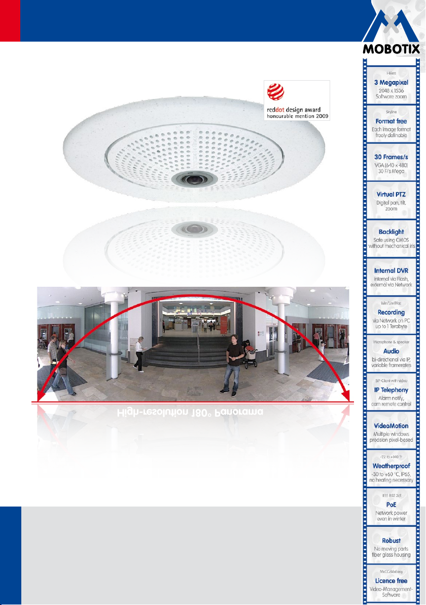
High-resolution 180° Panorama
Q24M: Camera Manual
Allround Easy. Allround Secure.
The HiRes Video Company
High-resolution 180° Panorama
Latest PDF file:
60.165_EN_V3_01/2013
HiRes Video Innovations
The German company MOBOTIX AG is known as the leading pioneer in network camera technology and its
decentralized concept has made high-resolution video systems cost ecient.
MOBOTIX AG • D-67722 Langmeil • Tel: +49-6302-9816-103 • Fax: +49-6302-9816-190 • sales@mobotix.com
www.mobotix.com
www.mobotix.com > Support > Manuals
Page 2

2/164
Q24M Camera Manual: Camera Data
MOBOTIX Camera Data
Enter your camera data here.
Camera Model:
Camera Name:
Factory IP Address:
Current IP Address:
DHCP:
Admin User Name:
Admin Password:
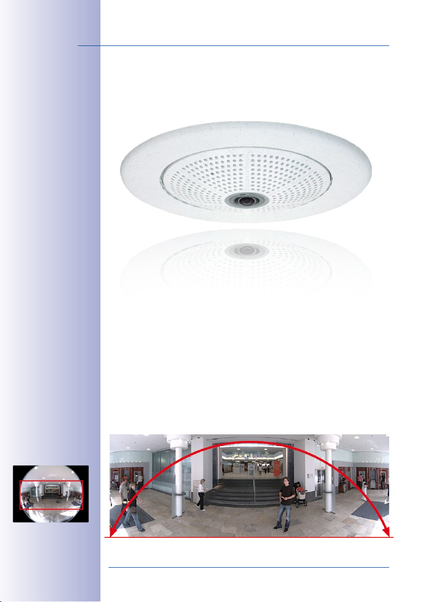
Original Q24M image;
Wall mounted at a height
of 2.3 m in a bank
High-resolution 180° Panorama
MOBOTIX Seminars
MOBOTIX oers inexpensive seminars that include workshops and practical exercises.
For more information, visit www.mobotix.com
© MOBOTIX AG • Security-Vision-Systems • Made in Germany
www.mobotix.com • sales@mobotix.com
> Seminars.
Page 3

Contents
CONTENTS
Foreword 8
The MOBOTIX Concept 10
Innovative Hemispheric Technology 12
MOBOTIX Hemispheric Technology 14
Superior Storage Solution 16
Added Security Value 18
Cost Benefits And Technical Advantages 20
1 Introduction 22
1.1 Q24M Overview 22
1.2 Q24M Next Generation Hemispheric Technology 31
1.3 General MOBOTIX Camera Functions 32
1.4 Lens Options, Hardware And Software Features 38
2 Installation 42
2.1 Preparing The Installation 42
2.1.1 Wall-Mounted 43
2.1.2 Ceiling-Mounted 46
2.1.3 Mounting Options 49
2.1.4 Network Connection And Power Supply, UPS 50
2.1.5 Preparing The Camera Connections, Wall Outlets 51
2.1.6 Wiring, Fire Prevention, Lightning And Surge Protection 52
2.2 Q24M Basic/Secure: Delivered Parts, Components, Dimensions 54
2.2.1 Delivered Parts And Camera Components 54
2.2.2 Camera Housing And Connectors 55
2.2.3 Q24M: Dimensions Without Mounting Options 56
3/164
2.3 Available Q24M Accessories - Overview 57
2.4 Mounting The Camera Without Accessories 64
2.4.1 Mounting Instructions 64
2.4.2 Required Tools 65
2.4.3 Procedure 66
© MOBOTIX AG • Security-Vision-Systems • Made in Germany
www.mobotix.com • sales@mobotix.com
Page 4

4/164
Q24M Camera Manual: Contents
2.5 Mounting The Camera With The On-Wall Set 70
2.5.1 Mounting Instructions 70
2.5.2 On-Wall Set 71
2.5.3 Procedure 74
2.6 Mounting The Camera With The In-Ceiling Set 76
2.6.1 Mounting Instructions 76
2.6.2 In-Ceiling Set0 77
2.6.3 Procedure 80
2.7 Installing The Vandalism Set 82
2.7.1 Mounting Instructions 82
2.7.2 Vandalism Set 83
2.7.3 Procedure 86
2.8 Installing The Wall Mount 88
2.8.1 Mounting Instructions 88
2.8.2 Wall Mount 89
2.8.3 Procedure 92
2.9 Installing The Corner And Pole Mount 94
2.9.1 Mounting Instructions 94
2.9.2 Corner And Pole Mount 95
2.9.3 Mounting To A Pole 97
2.9.4 Mounting To A Wall Or Building Corner 98
2.9.5 Mounting The Wall Mount To The Corner And Pole Mount 99
2.10 Replacing The MicroSD Card 100
2.10.1 Removing The MicroSD Card 100
2.10.2 Inserting A MicroSD Card 101
2.11 Network And Power Connection 102
2.11.1 Notes On Cable Lengths And Power Supply 102
2.11.2 PoE Variables 102
2.11.3 Power Supply Using A Switch 103
2.11.4 Power Supply When Connected Directly To A Computer 104
2.11.5 Power Supply (PoE IEEE 802.3af) Using Power-over-Ethernet Products 104
2.11.6 Camera Startup Sequence 105
3 Operating The Camera 106
3.1 Manual and Automatic Operation– Overview 106
3.1.1 Manually Using A Computer In The 10.x.x.x IP Address Range 107
3.1.2 Automatically Using MxControlCenter Or MxEasy 108
3.1.3 Automatically Using DHCP 109
© MOBOTIX AG • Security-Vision-Systems • Made in Germany
www.mobotix.com • sales@mobotix.com
Page 5

Contents
3.2 First Images And The Most Important Settings 110
3.2.1 Manually Setting Up The Network Parameters In A Browser 110
3.2.2 First Images And The Most Important Settings In The Browser 112
3.2.3 First Images And Network Parameter Configuration In MxControlCenter 114
3.2.4 First Images And Network Parameter Configuration In MxEasy 119
3.2.5 Integrating And Displaying Cameras 120
3.2.6 Starting The Camera With The Factory IP Address 122
3.2.7 Starting The Camera With An Automatic IP Address (DHCP) 123
3.3 Virtual PTZ And Full Image Recording 124
3.3.1 Preparing The Virtual PTZ Function 124
3.3.2 Full Image Recording 126
3.3.3 Special Q24M Configuration In The Browser 128
3.4 MicroSD Card Recording 135
3.4.1 Introduction 135
3.4.2 Formatting The MicroSD Card 137
3.4.3 Activate Recording 138
3.4.4 Accessing Camera Data 139
3.4.5 Deactivating The Card Memory 139
3.4.6 Using A MicroSD Card In A Dierent MOBOTIX Camera 140
3.4.7 Limitations On Warranty When Using Flash Storage Media 140
3.5 Configuration In The Browser 141
3.5.1 Overview 141
3.5.2 General Browser Settings 141
3.5.3 Additional Configuration Options 144
5/164
3.6 Additional Notes 145
3.6.1 Weatherproofness 145
3.6.2 Password For The Administration Menu 145
3.6.3 Permanently Deactivating The Microphone 145
3.6.4 Starting The Camera With The Factory IP Address 145
3.6.5 Resetting The Camera To Factory Settings 146
3.6.6 Activate Event Control And Motion Detection 146
3.6.7 Deactivate Text And Logo Options 146
3.6.8 Deactivating The Camera Reboot 146
3.6.9 Browser 147
3.6.10 Cleaning The Camera And Lens 147
3.6.11 Safety Warnings 147
3.6.12 Online Help In The Browser 148
3.6.13 RoHS Declaration 148
3.6.14 Disposal 148
3.6.15 Disclaimer 149
© MOBOTIX AG • Security-Vision-Systems • Made in Germany
www.mobotix.com • sales@mobotix.com
Page 6
6/164
§
Q24M Camera Manual: Contents
Important Notes
Electrical Installation
Electrical systems and equipment may only be set up, changed and maintained by
a qualified electrician or under the direction and supervision of a qualified electrician
in accordance with the appropriate electrical guidelines.
Legal Aspects Of Video And Sound Recording
You must comply with all data protection regulations for video and sound monitor
ing when using MOBOTIX products. Depending on national laws and the installation
location of the IP Video Door Station, the recording of video and sound data may be
subject to special documentation or it may be prohibited. All users of MOBOTIX
products are therefore required to familiarize themselves with all valid regulations
and comply with these laws. MOBOTIX AG is not liable for any illegal use of MOBOTIX
products.
Network Security
MOBOTIX products include all of the necessary configuration options for operation
in Ethernet networks in compliance with data protection laws. The operator is responsible for the data protection concept across the entire system. The basic settings
required to prevent misuse can be configured in the software and are passwordprotected. This prevents unauthorized parties from accessing these settings.
Never Remove The Dome
The MOBOTIX cameras S14D and S14M should never be operated without their
preinstalled transparent domes (sensor modules S14D and housing S14M) or protective lens screens (sensor modules S14D). The camera is no longer weatherproof
when operated without the domes or protective lens screens. The exposed metal
ring around the lens can become extremely hot when the exterior temperature is
high. Touching this ring can cause burns.
-
Additional Information:
www.mobotix.com
© MOBOTIX AG • Security-Vision-Systems • Made in Germany
www.mobotix.com • sales@mobotix.com
Page 7

Contents
Notes And Copyright Information
Download the latest version of this manual, of the Camera Software
Manual and the manuals for MxEasy and MxControlCenter as PDF files from
www.mobotix.com (
Support > Manuals
).
Additional information:
www.mobotix.com
7/164
All rights reserved.
protected trademarks of MOBOTIX AG.
registered trademarks of Microsoft Corporation.
OSX, Bonjour
Computer, Inc.
sion brands and logos referred to are brands, service provision brands and logos
belonging to their respective owners.
Copyright © 1999–2013, MOBOTIX AG, Langmeil, Germany. Information subject to
change without notice!
MOBOTIX
™,
MxControlCenter®
Microsoft, Windows
, the Bonjour logo and the Bonjour symbol are trademarks of Apple
Linux
is a trademark of Linus Torvalds. All other brands, service provi-
and
MxEasy®
Apple
, the Apple logo,
are internationally
and
Windows Server
are
Macintosh
,
© MOBOTIX AG • Security-Vision-Systems • Made in Germany
www.mobotix.com • sales@mobotix.com
Page 8
8/164
Q24M Camera Manual: Foreword
FOREWORD
Dear MOBOTIX customer,
Congratulations on purchasing this globally unique and discreet hemispherical network
camera “Made in Germany”. With its wide range of image display options such
as the panorama function, a virtual PTZ function and live distortion correction,
the Q24M oers whole new application possibilities. Proven MOBOTIX concept
advantages such as
as modern and highly beneficial long-term flash storage located directly in
the camera, are also available.
This Camera Manual Part 1 will give you an initial overview of the innovative
underlying MOBOTIX concept. This includes all the information you need to unpack
and install the camera (Chapter 2) and to view initial images on a PC (Chapter 3).
Please see the Software Camera Manual Part 2, included in the camera packaging, for
information on how to work with the many camera functions, such as e.g. event control
or image storage.
integrated event, alarm and telephony functions
, as well
If you would prefer to work with MxEasy or MxControlCenter instead of the browser con
trolled MOBOTIX camera software, you can download these programs for free including
a manual (PDF) from the MOBOTIX website:
www.mobotix.com/eng_US/Support/Software-Downloads
If you have any questions, our support and international sales stas are available under
intl-support@mobotix.com from Monday to Friday, 8 a.m. to 6 p.m (German time).
We would like to thank you for your trust and wish you all the best with your new MOBOTIX
camera!
-
© MOBOTIX AG • Security-Vision-Systems • Made in Germany
www.mobotix.com • sales@mobotix.com
Page 9
9/164
Q24M with 10°
On-Wall mount
© MOBOTIX AG • Security-Vision-Systems • Made in Germany
www.mobotix.com • sales@mobotix.com
Q24M with
In-Ceiling mount
Page 10
10/164
Q24M Camera Manual: The MOBOTIX Concept
THE MOBOTIX CONCEPT
HiRes Video Innovations
The German company MOBOTIX AG is known as the leading pioneer in network
camera technology since its founding in 1999, and its decentralized concept, has
made high-resolution video systems cost ecient. Whether in embassies, airports,
railway stations, ports, gas stations, hotels or on highways - over one hundred thousand
MOBOTIX video systems have been in operation on every continent for years.
Technology Leader Of Network Cameras
In a short time, MOBOTIX has gained the second place in Europe and the fourth place
worldwide in terms of market share. MOBOTIX has been solely producing megapixel
cameras for years and, in this area, ranks as global market leader in high-resolution
video systems with a market share of over 60%.
Why High-Resolution Systems?
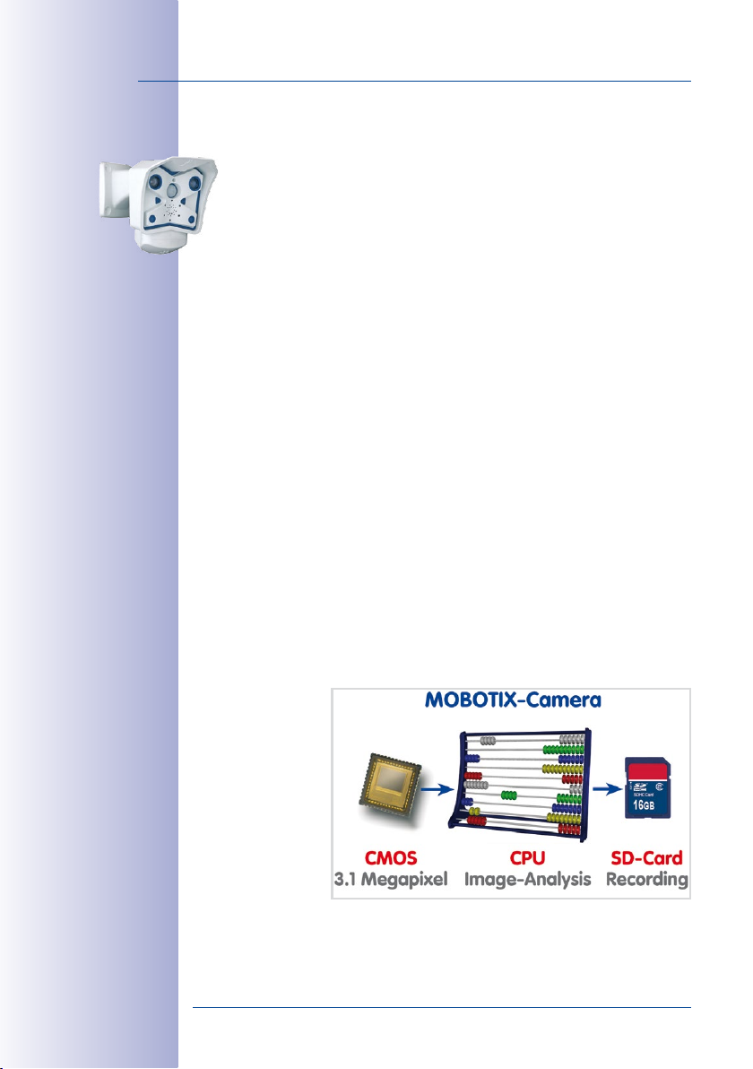
The higher the resolution, the more accurate the detail in the image. With the old analog
technology, a live image has no more than 0.4 megapixels and a recorded image generally
0.1 megapixels (CIF).On the contrary, one MOBOTIX camera with 3.1 megapixels records
around 30 times more detail. As a result, larger image areas with up to 360° allround
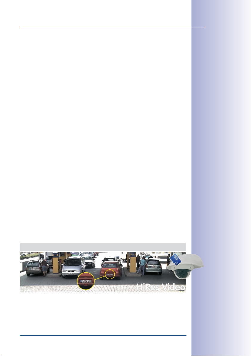
views are possible, thus reducing the number of cameras and therefore the costs. For
example, four lanes of a gas station can be recorded with one MOBOTIX camera instead
of four conventional cameras.
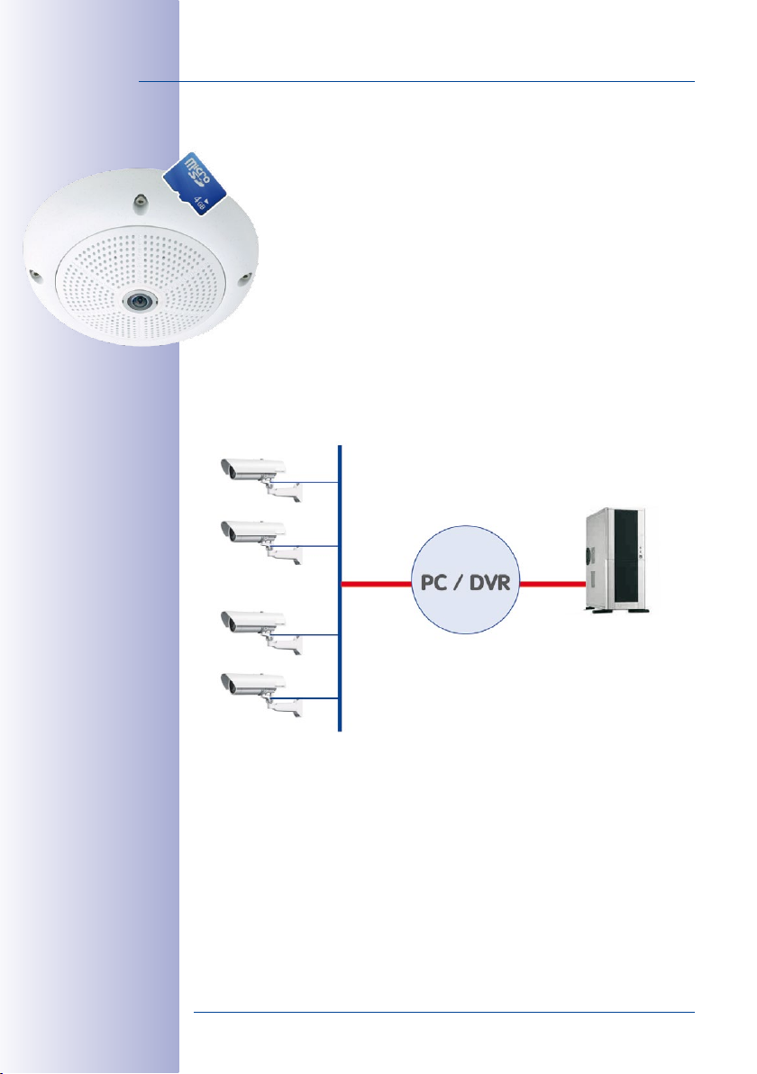
Disadvantages Of Old Centralized Solution
Usually cameras only supply the images while the processing and recording is done later
on a central PC using video management software. This traditional centralized structure has
many limitations, since it requires a high network bandwidth and the PC processing power
is not enough for several cameras. A HDTV MPEG4 film already puts considerable strain on
a PC, how can it be expected to process dozens of high-resolution live cameras? Traditional
centralized systems
are therefore less suitable and unprofitable
than high-resolution
systems due to the
high number of PCs
needed.
© MOBOTIX AG • Security-Vision-Systems • Made in Germany
www.mobotix.com • sales@mobotix.com
Page 11
The Decentralized MOBOTIX Concept
Unlike with other systems, with the decentralized MOBOTIX concept a high-speed
computer and, if requested, digital memory (SD card) is built into every camera
for long-term recording. The PC now serves purely for viewing, not for analysis or
recording. As a result, MOBOTIX cameras can record in response to an event even
without the PC being switched on and digitally store the videos with sound.
The Benefits
MOBOTIX video solutions therefore require significantly:
• fewer cameras due to the more accurate detail of panoramic images with mega
pixel technology,
•
fewer PCs/DVRs, because around 40 cameras can store high-resolution videos with
sound eciently on a single PC, or no PC at all when recording in the camera using
digital memory (USB, SD card),
• lower network bandwidth, because everything is processed in the camera itself
and the high-resolution images therefore do not have to be constantly transported
for analysis.
Robust And Low-Maintenance
MOBOTIX cameras have no mechanical motors for lenses or for movement. Without any
moving parts, they are therefore so robust that maintenance is reduced to a minimum.
The unique temperature range from -30°C to +60°C is achieved without heating or fan
at approximately 4.5 watts. Since no PC hard disk is required for recording, there are no
parts that wear out in the entire video system.
Software Included - For Life
There are no software and licensing costs with MOBOTIX, because the software is always
supplied with the camera; for an unlimited number of cameras and users. The software
package supplied with the camera also includes professional control room software, like
that used in football stadiums, for example. Updates are supplied free of charge on the
website. The system price for a weatherproof camera including lens, query software and
day-to-day recording on the SD card is under 1,000 euro.
11/164
-
One Camera for 4 Gas Pumps - Long-Term Recording Without Peripheral Devices
© MOBOTIX AG • Security-Vision-Systems • Made in Germany
www.mobotix.com • sales@mobotix.com
Page 12
12/164
Fisheye view
Q24M Camera Manual: Innovative Hemispheric Technology
INNOVATIVE HEMISPHERIC TECHNOLOGY
The Hemispheric Camera
The primary components of a hemispheric camera include a fisheye lens, a high-resolu
tion image sensor, and image correction software that is integrated into the camera. Using
an ultra-wide angle fisheye lens, the hemispheric camera captures a 180°-hemispheric
image of the room and projects it onto a high-resolution image sensor.
L11 (fisheye)
Hemispheric
panorama view
vPTZ 1 vPTZ 2
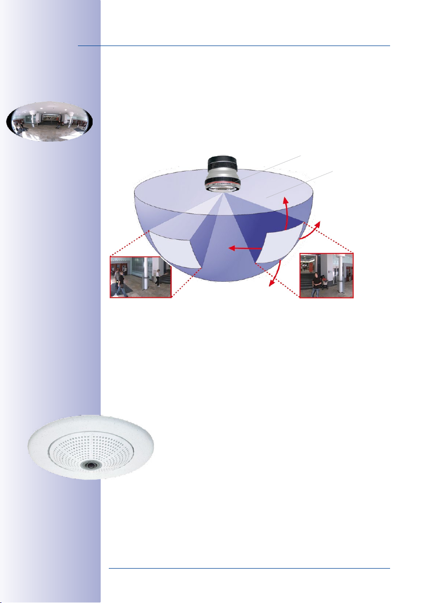
When ceiling mounted, the image area of the hemispheric camera covers the entire room.
The image in the hemisphere is convex, particularly near the image borders. These image
sections are corrected for the viewer by the integrated distortion correction software,
allowing a view of the scene from the usual perspective. The virtual PTZ feature allows
you to enlarge or move image sections within the hemisphere just like PTZ camera, yet
without the need for moving parts.
-
Q24M with
In-Ceiling mount
Handle Several Image Sections at Once
One or more image sections can be corrected for perspective in the hemispheric view,
allowing you to monitor and record several dierent areas of a room at the same
time, something that a mechanical PTZ camera is not capable of doing.
Discreet and Low Maintenance
Hemispheric cameras are extremely discreet because they manage their
task with only one lens, which is generally focused on an entire room
and not a specific object. Hemispheric cameras are without mechanical
moving parts and require low maintenance. In addition, they are silent when
panning and focusing on a specific image area.
© MOBOTIX AG • Security-Vision-Systems • Made in Germany
www.mobotix.com • sales@mobotix.com
Page 13
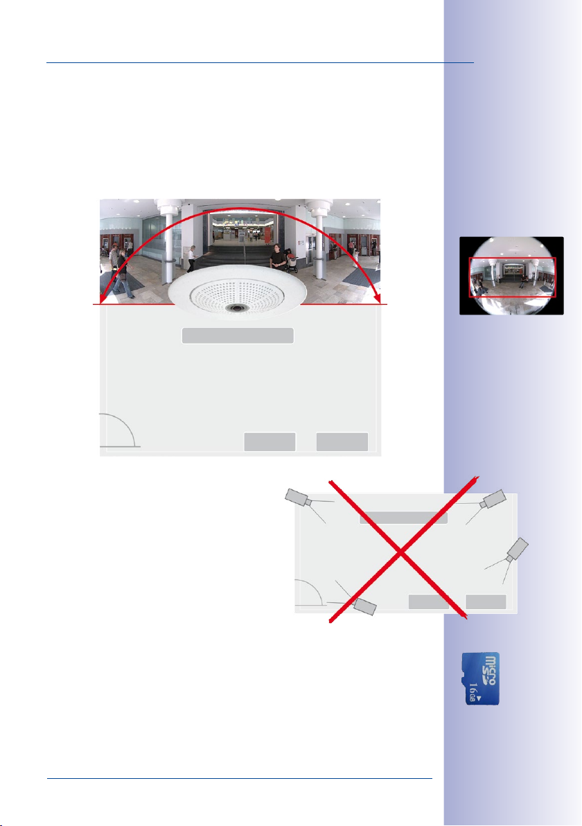
Less Cameras Thanks To Panoramic Views
The perspective of the hemispheric image can also be transformed into an ultra-wide
angle panoramic view spanning 180° if the camera is mounted on a wall, providing a
wall-to-wall view of the room without any blind spots. It oers a substantially better view
of the scene, compared to other cameras, and it also results in the need for fewer cameras
overall. When ceiling mounted, one camera can also capture an entire room by two
opposite panoramic views.
Lobby
Hemispheric 180° panorama
Surveillance of a room with only one camera
with no blind spots
Elevator
Elevator
13/164
Original Q24M image;
wall-mounted at a
height of 2.3 m/7.5 ft
Hemispheric room coverage with wall mounting – one Q24M replaces
four standard cameras
Keeping Objects In View At All Times
Using solutions featuring several individual cameras,
moving objects will normally jump from one viewing
area of a camera to another. This often produces a
confusing situation for the viewer because objects may
disappear from sight for a moment or even appear
twice if the viewing areas overlap. This is not the case
with hemispheric panoramic cameras. Objects remain
in view at all times and the viewer can always keep
good track of objects in the scene.
Everything Stored In The Recording
Traditional optical PTZ cameras can only record what is being viewed live. The virtual PTZ
feature from MOBOTIX allows users to pan to other areas at a later stage in the recording
because the entire room can be recorded as a hemispheric image.
FOURSTANDARD CAMERAS
Capture less than one single S14M
Lobby
Elevator Elevator
© MOBOTIX AG • Security-Vision-Systems • Made in Germany
www.mobotix.com • sales@mobotix.com
Integrated
MicroSD card
(max. 64 GB)
Page 14
14/164
I
h
t
i
w
M
4
2
Q
Original image Q24M;
mounted to a wall in
2.3 m height in a bank
Q24M Camera Manual: MOBOTIX Hemispheric Technology
MOBOTIX HEMISPHERIC TECHNOLOGY
Perfect Room Overview
With the innovative MOBOTIX Hemispheric Technology, an entire room can be ideally
C
e
-
i
l
n
i
n
g
m
o
u
n
t
When several cameras are monitoring a single room, it is dicult to understand the room
layout in its single view. This makes it hard to comprehend the overall setting. The new
panorama function of the Q24M delivers a widescreen image of a high-resolution 180°
allround view. High image quality is achieved through the use of a 3.1 megapixel sensor
and the new hemispheric lens.
monitored. For instance, one single, particularly elegant and discreet, Q24M
replaces the time-consuming and expensive installation of several standard
cameras. This world first demonstrates again the innovative strength of
MOBOTIX as a global leader for megapixel video security systems.
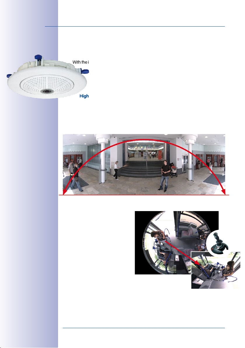
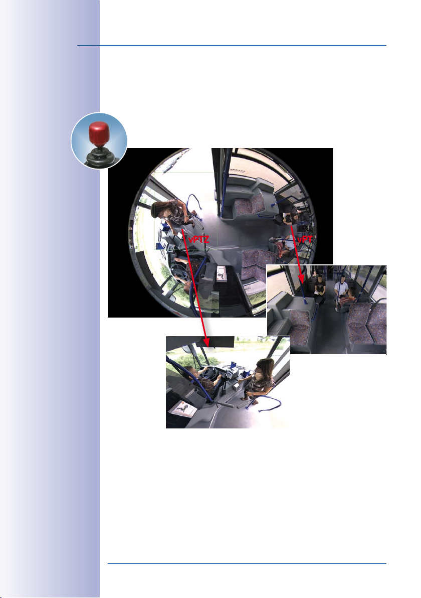
High-Resolution 180° Panorama
High-resolution 180° panorama
vPTZ controla also
via USB joystick
Virtual PTZ (vPTZ) – Without Motor
The Q24M also zooms in on detail.
The image of the Hemispheric cam
era can be continuously enlarged
and any image section examined
using a joystick, for example. Thus
you have a mechanical PTZ-camera
without maintenance or wear and
tear. While zooming into a section in
the live image, a full image can be
stored in the recording for later analysis. No PTZ-camera in the world that
operates with a motor can do that!
© MOBOTIX AG • Security-Vision-Systems • Made in Germany
-
vPTZ
www.mobotix.com • sales@mobotix.com
Page 15
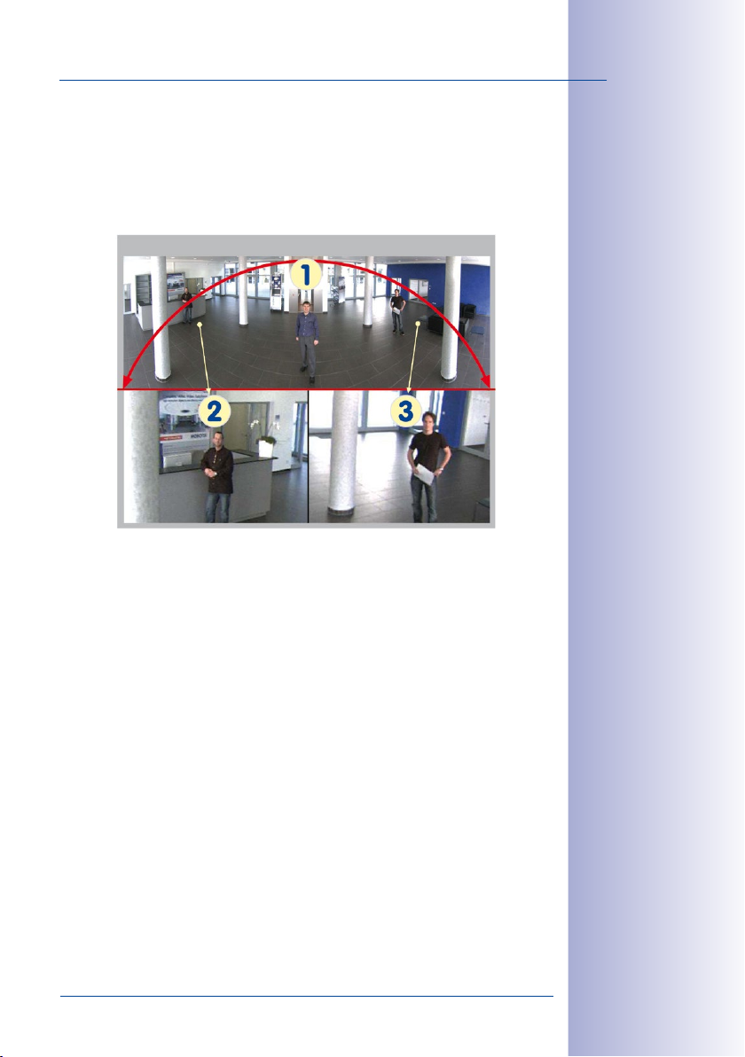
One Camera, More Views
The surround function of the Q24M (ceiling mounted) immediately replaces four conven
tional cameras and shows four dierent directions simultaneously in quad view on a
monitor. Virtual PTZ is available for each of the four views. Together with the 180° panorama
the Q24M can deliver two more views simultaneously, making it possible to see the
overview and to focus on two scenes at the same time (Display Mode “Panorama Focus“).
The Q24M Panorama: one camera - three simultaneous views
High-resolution 180° panorama
Virtual PTZ 1 Virtual PTZ 2
Highly User-Friendly
The full image from a hemispheric lens (Fisheye) is dicult to analyze. MOBOTIX solves this
problem by perfectly straightening the uneven lines in the live image using the camera
software. Since the image distortion correction of the hemispheric view and the generating
of the panoramic view take place in the camera itself, no additional load is placed on the
viewer PC, unlike a “standard” camera. Thus, displaying a large number of panoramic
cameras simultaneously on a single PC is possible.
-
Panorama Focus:
Original Q24M image
15/164
Highly Ecient Image Transferring
While other camera systems always transfer the full images via the network for further
analysis, a MOBOTIX camera sends only the relevant image sections. Therefore, a Q24M
panorama image needs only about 1/6 of the original data volume or bandwidth. This
means up to six times more MOBOTIX cameras can transfer images over a network
compared to “standard” cameras.
Internal DVR With 32 GB
The Q24M stores high-resolution video with sound directly on the integrated Flash memory
without using an external recording device or PC, therefore using no additional network
load. Old recordings can be overwritten automatically or deleted after a predefined period.
The storage capacity is sucient for around 400,000 panorama images or 33 hours of
film (32 GB MicroSD).
© MOBOTIX AG • Security-Vision-Systems • Made in Germany
www.mobotix.com • sales@mobotix.com
Page 16
16/164
Q24M Camera Manual: Superior Storage Solution
SUPERIOR STORAGE SOLUTION
The Market Demands Better Image Quality
When it comes to future-proof video surveillance systems, it is not a matter
of analog or digital but whether it is high-resolution or not. It is important
to note that HiRes video only with decentralized network camera technol
ogy can be implemented at much lower cost than any other type of video
surveillance system.
Central Storage As A Bottleneck
These days, video data is normally pre-processed and stored centrally on
a PC or DVR using video management software. Video and audio streams
from all installed cameras are directed to this central device. This system
is comparable to a highway at rush hour: the more cameras there are, the
faster a data jam on the PC or DVR occurs. This means that despite HiRes cameras, the
data is generally not stored in high-resolution format.
NON-MOBOTIX System
-
Motion detection and pre-
alarm buer are in the PC
(bottleneck)
Storage
Central PC is a bottleneck and a risk for the entire system
MOBOTIX Stores HiRes Cost Eciently
MOBOTIX solves the PC storage bottleneck problem using a unique and yet amazingly
eective method - through the camera itself. High-resolution video with lip synchronized
sound is saved either remotely over the network or locally on flash memory devices (com
mercial SD or CF cards, USB memory).
© MOBOTIX AG • Security-Vision-Systems • Made in Germany
www.mobotix.com • sales@mobotix.com
-
Page 17
Flash memory is a sophisticated form of semiconductor memory without mechanical
moving parts and represents the storage medium of the future thanks to its reliability,
ease of use and low cost.
MOBOTIX System
Network
Software and storage integrated in MOBOTIX cameras
MOBOTIX Stores Data In Flash Memory
• No PC / network is needed for operations and there is no network load
• USB flash media can be connected directly to the camera (instead of internal SD /
CF card); no network is necessary
• Greater reliability (no hard disk drive)
• Ring buer: Old images can be overwritten automatically or deleted after a speci
fied time
MOBOTIX Stores Data Reliably
MOBOTIX’ own flash file system (MxFFS) prevents unauthorized persons from reading or
transferring the internally stored data, even if the card is stolen.
17/164
-
MOBOTIX Only Saves What Is Necessary
The MOBOTIX system includes three important
additional options that allow more data to be
stored for a longer time:
Only the relevant image sections are stored
•
instead of the entire image (for example,
sky or ceiling is removed)
• Video recording only begins when relevant
events take place (such as movement in
the image)
• Temporarily increased frame rate during
continuous recording of events
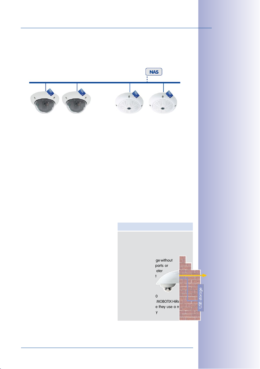
By connecting external memory over the network
(NAS), the system can be expanded without limitations even while it is running.
MOBOTIX Data Storage
• Inside the camera - a 16 GB SD card is
enough to record all day long, making cen
tral data storage devices or PCs unnecessary
• In USB memory (connection via
USB cable) data storage without
mechanical moving parts or
network load (greater
protection against
data theft)
• A file server (NAS)
can store around 10
times more data from MOBOTIX HiRes cam-
eras (than usual)since they use a memory
organization internally
© MOBOTIX AG • Security-Vision-Systems • Made in Germany
www.mobotix.com • sales@mobotix.com
-
Page 18
Added Security Value
18/164
Q24M Camera Manual: Added Security Value
ADDED SECURITY VALUE
Q24M Panorama: one camera - three simultaneous views
High-resolution 180° panorama
Virtual PTZ 1 Virtual PTZ 2
The security barriers that are built into the camera are extremely secure. The camera
images are only accessible to authorized persons and are encrypted via SSL when they
are transferred over the network.
Notification Of Failure
MOBOTIX cameras will automatically report any impairment or failure. This ensures maxi
mum reliability and readiness for use.
Robust, Low-Maintenance Technology
The real added value of MOBOTIX products is
reflected in characteristics such as enhanced
functionality, long life and robustness. MOBOTIX
cameras basically have no moving parts. This
makes the cameras very resistant to wear and
tear, and reduces both maintenance costs and
power consumption.
Alarm Management And Forwarding
Integrated sensors enable MOBOTIX cameras to
recognize when an event has occurred. If neces
sary, the cameras will respond immediately with
an alarm tone and will establish a direct video and
sound connection to a control room.
Absolute Data Security
-
-
Floor plan and camera
view in MxControlCenter
(free control center software from
MOBOTIX)
Subsequent Searches
Events rarely confine themselves to just one spot. So even when you are looking at an
enlarged detail in live mode, it is always a full image that is recorded. And in this full
image, any section can always be enlarged later or whenever necessary.
© MOBOTIX AG • Security-Vision-Systems • Made in Germany
www.mobotix.com • sales@mobotix.com
Page 19
Sound Increases The Chance Of Detection
In the event of an alarm, MOBOTIX cameras can turn on their built-in microphones and
record lip-synchronous sound. They are therefore an even greater help in analyzing a
situation and easing clarification. In addition, the video system can be used for bidirectional
communication via a loudspeaker/microphone.
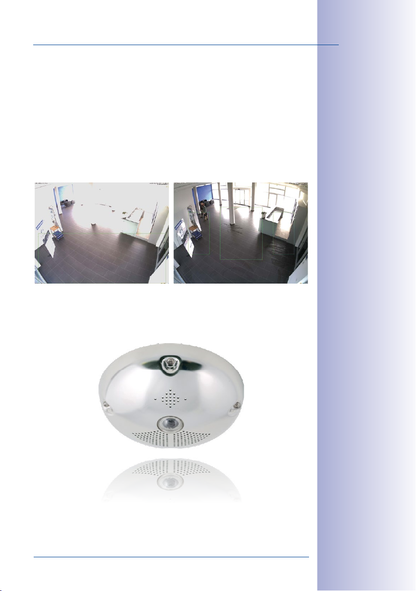
No Problems With Backlight
MOBOTIX cameras are not aected adversely by sunlight such as direct sunlight. They
deliver meaningful, detailed images all the time, because the camera software supports
easy programming of independent exposure windows to cope with specific situations.
This makes them ideal for rooms with large glass fronts.
Vandalism-Proof Models
In critical environments or for outdoor use, it is often best to choose vandalism-proof
MOBOTIX cameras. Their steel housing resists even the hardest attacks, and the cameras
will deliver a perfect picture of the attackers.
19/164
Placing the exposure window in the lower image
area (left image) delivers
less optimum results
compared to moving
three individual exposure
windows up toward the
windows (right image)
© MOBOTIX AG • Security-Vision-Systems • Made in Germany
www.mobotix.com • sales@mobotix.com
Page 20
20/164
Fiberglass-reinforced composite housing with built-in cable protection and
Q24M Camera Manual: Cost Benefits And Technical Advantages
THE MOST IMPORTANT COST BENEFITS
Increased Resolution Reduces Amount Of Cameras Needed
1536 lines, high-resolution sensors give a better overview and allow monitor-
1
ing an entire room with just one camera.
Reduced Installation Costs At Any Distance
Standard Ethernet connection enables the use of common network compo-
2
nents such as fi ber, copper and wireless (WLAN).
Intelligent Cameras Reduce The Number Of Storage Devices
The decentralized MOBOTIX concept enables the user to save around 10 times
3
the standard number of cameras using just one storage device.
Event-Controlled Image Format Minimizes Storage Costs
Automatic image adjustment (frame rate, size) in the case of movement, noises
4
or sensor action reduces bandwidth and storage requirements.
Low Power Costs, No Extra Heating
Anti-fogging without heating allows the system to be powered throughout the year
5
using network cable or two wires (PoE standard) and saves on the cost of power cabling.
Backup Power Supply Costs Reduced By 80%
Low power consumption, approx. 5 watts, enables year-round PoE (no heating
6
required) with one centralized UPS from the installation room using network cable.
Robust And Practically Maintenance-Free
7
no mechanical moving parts (no auto iris) guarantees longevity.
Software For A Thousand Cameras & Storage Devices Included
The right premium operating software for every application: MxEasy for com-
8
pact video solutions, MxControlCenter for the professional control center.
Unlimited Scalability And High Return On Investment
More cameras and storage can be added at any time – even while the system is in
9
use; image format, frame rate and recording parameters can be camera-specifi c.
Additional Functions And Other Extras Included
Sound support, lens, wall mount and weatherproof housing (-30 to +60°C/-22 to +140°F)
10
are included in the camera delivery; microphone and speakers available for most models.
© MOBOTIX AG • Security-Vision-Systems • Made in Germany
www.mobotix.com • sales@mobotix.com
Page 21
THE MOST IMPORTANT TECHNICAL ADVANTAGES
High-Resolution Digital Image Instead Of TV Quality
Megapixel sensor and image processing inside the camera generate sharp images with a
higher resolution than HDTV, allowing them to be recognized as evidence in a court of law.
Hemispheric Technology For An Overview With No Blind Spots
360° allround view or 180° widescreen image, corrected for perspective; only one
camera is needed to view the entire room or train platform without any blind spots.
Bridging Of Recording During Network Failures
In-camera data storage (up to 64 GB) can even bridge longer network
failures or bandwidth fl uctuations (for example with wireless networks).
Professional Software For Systems Of Any Size
This control center and recording software, which is free of charge and used in tens of thousands of systems around the world, sets no limits on the number of users, cameras or servers.
Very Low Network Load
E cient video codecs, motion detection and data storage of up to 64 GB in
the camera guarantee a very low network load.
No Storage Limit
There is no storage limit for the entire system because each camera is able
to manage its own terabyte-sized storage device (NAS) via the network.
1
2
3
4
5
6
21/164
Sun And Backlight Compensation
CMOS-sensor without auto iris, digital contrast enhancement and confi gurable exposure measurement zones guarantee optimum exposure control.
Day & Night Maintenance-Free
MOBOTIX dual cameras with two sensors and digital switching between day and
night modes operate reliably with no mechanical components in all lighting conditions.
Simultaneous Recording, Event Search And Live Viewing
Live video for multiple users, simultaneous recording and event search possible
in seconds from anywhere in the world via a network connection.
Sound And SIP Telephony
Lip-synchronous sound (live & recording); every camera is also a video IP telephone
compliant with the SIP standard, featuring camera control and automatic alarm calls.
© MOBOTIX AG • Security-Vision-Systems • Made in Germany
www.mobotix.com • sales@mobotix.com
7
8
9
10
Page 22
22/164
Q24M Camera Manual: Introduction
1 INTRODUCTION
1.1 Q24M Overview
c
-
e
n
i
li
i
n
h
t
i
w
M
4
2
Q
Innovative Hemispherical Technology For The Perfect Room Overview
The MOBOTIX Q24M Hemispheric camera is an elegant, ultra-compact and weather proof
IP network dome camera with a special hemispheric lens (fisheye). When mounted on the
ceiling, the camera is capable of providing full 360° allround view or a 180° widescreen
panorama when mounted on a wall. The first of its kind in the world, this camera is
evidence of the MOBOTIX commitment to innovation as the global leader in megapixel
video security cameras.
g
m
o
u
n
t
Original Q24M image;
Wall mounted at a height
of 2.3 m in a bank
Original full image
High-Resolution 180° Panorama (Wall-Mounted)
When several cameras are monitoring a single room, it is dicult to understand the room
layout in its single view. This makes it hard to comprehend the overall setting. The new
panorama function of the Q24M delivers a widescreen image of a high-resolution 180°
allround view. High image quality is achieved through the use of a 3.1 megapixel sensor
and the new hemispheric lens.
High-resolution 180° panorama
© MOBOTIX AG • Security-Vision-Systems • Made in Germany
www.mobotix.com • sales@mobotix.com
Page 23
Q24M Overview
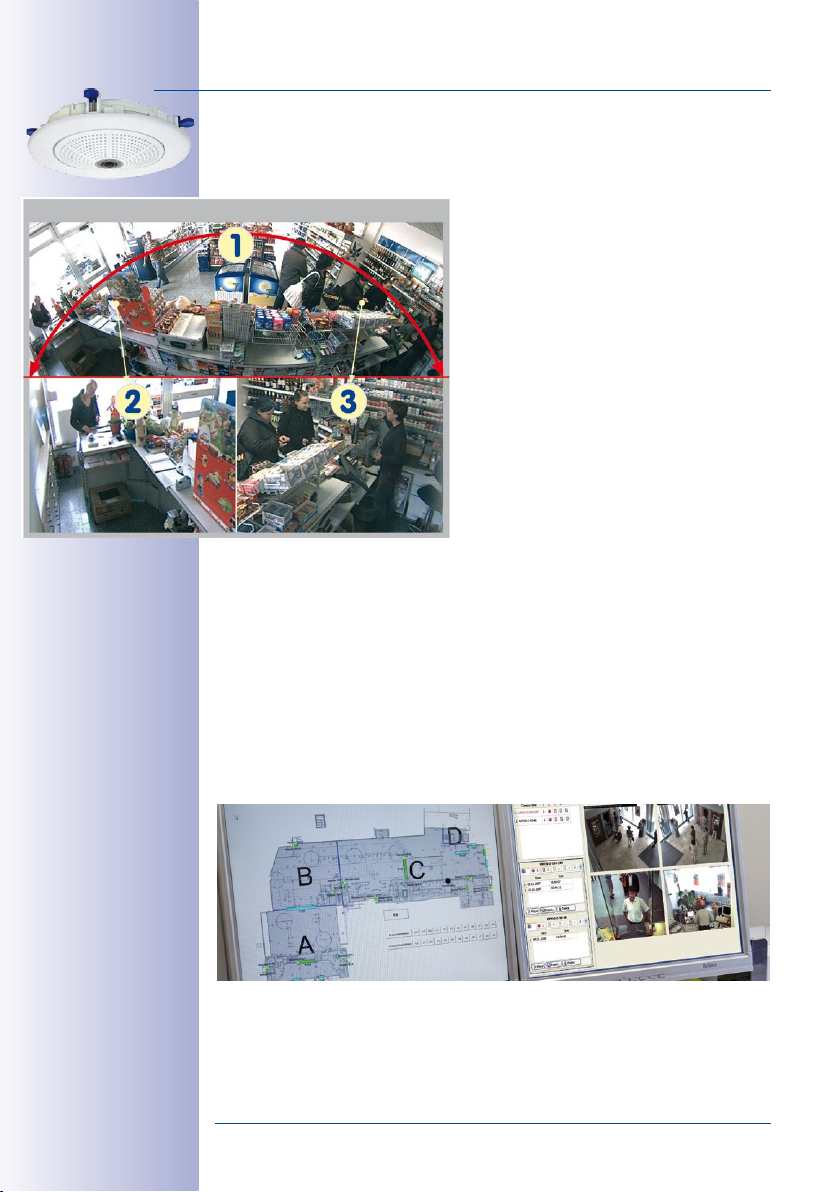
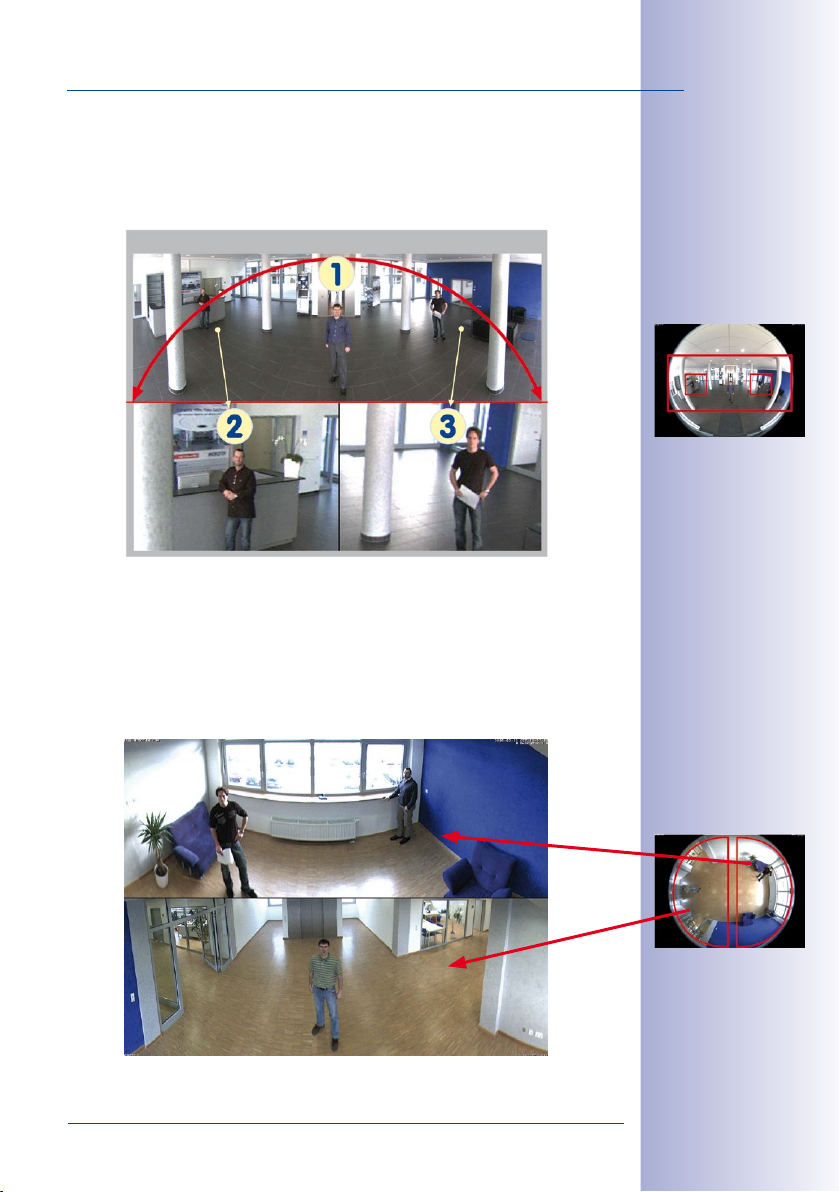
Panorama Focus – One Camera, Three Views (Wall-Mounted)
Maximum room overview while simultaneously viewing detail in a single image: the Q24M
is capable of providing two more views at the same time with the 180° panorama, allowing you to focus on two scenes in parallel ("Panorama Focus" display mode).
The Q24M Panorama: one camera - three simultaneous views
High-resolution 180° panorama
Virtual
PTZ 1 Virtual PTZ 2
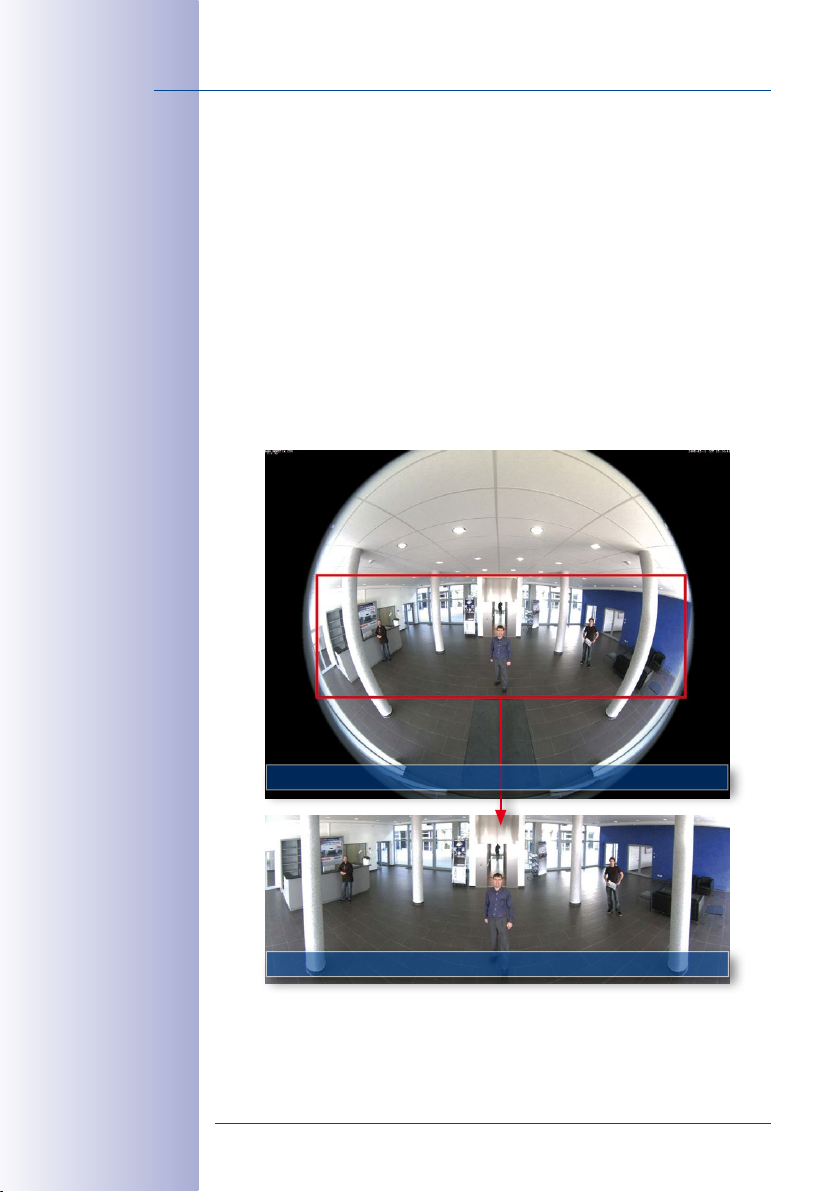
Double Panorama For A Simultaneous View In Two Directions (Ceiling-Mounted)
When the camera is mounted in the center of the ceiling of a room, "Double Panorama"
display mode provides a corrected panorama image of both halves of the room. It cor
responds roughly with the situation of personally standing in the middle of the room and
being able to look both forwards and backwards at the same time. A superb overview
for the user – provided by a single Q24M camera alone.
23/164
Panorama Focus:
Original Q24M image
Original full image
-
© MOBOTIX AG • Security-Vision-Systems • Made in Germany
www.mobotix.com • sales@mobotix.com
Double Panorama:
Original Q24M image
Original full image
Page 24
24/164
Q24M Camera Manual: Introduction
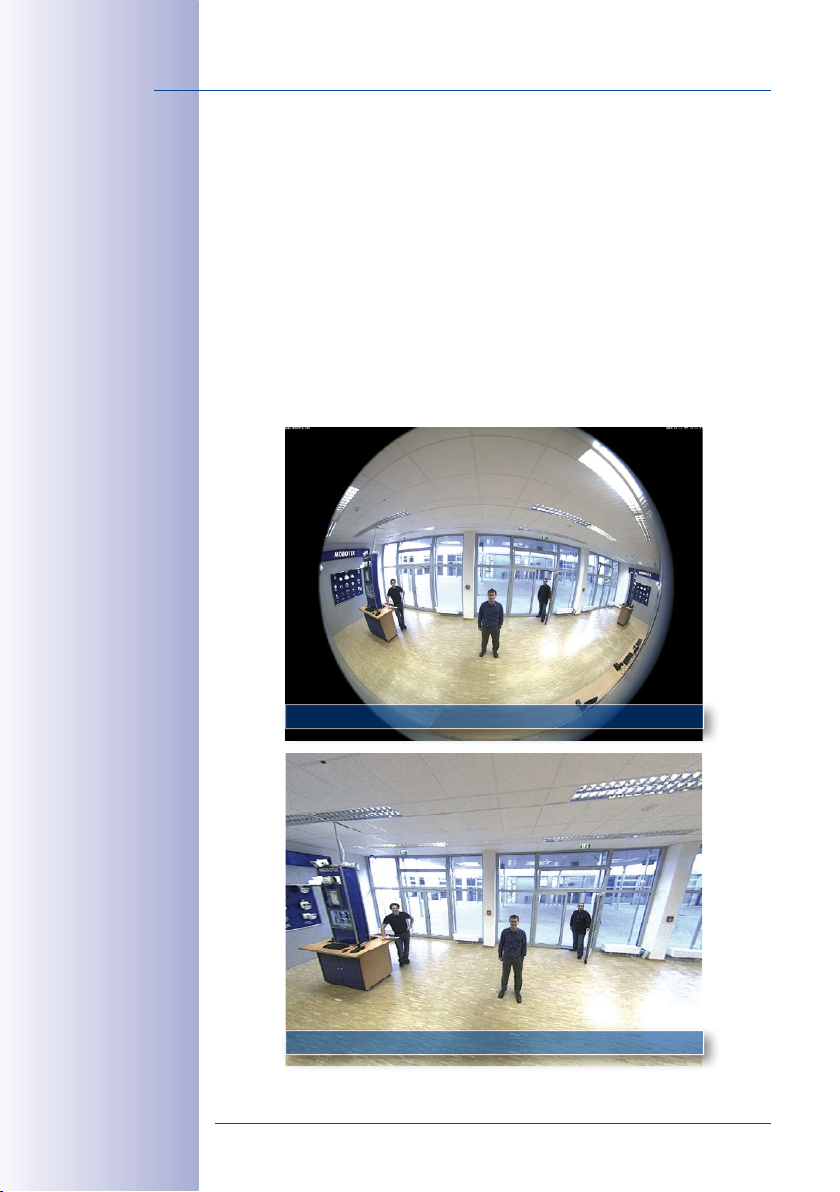
Full Image And Normal View
With innovative MOBOTIX Hemispheric Technology, an entire room can be ideally monitored.
For instance, one single, particularly elegant and discreet, Q24M replaces the time-consuming
and expensive installation of several standard cameras. The overview image provided by a
single Q24M, which may be tailored in a number of ways according to specific user require
ments, not only reduces the number of required cameras, but also minimizes the system
costs by reducing the wiring complexity, emergency power requirements and number of
recording devices required.
In addition to Panorama, Double Panorama and Panorama Focus views, the Q24M image
may be displayed on a monitor in the original fisheye version ("Full Image" display mode),
the camera-corrected full image ("Normal" display mode) and in a quad view of all four
directions ("Surround" display mode). Switching to a dierent display mode is possible at
any time within seconds.
-
Fisheye Original Image: Full Image
Corrected Image Section: Normal
© MOBOTIX AG • Security-Vision-Systems • Made in Germany
www.mobotix.com • sales@mobotix.com
Page 25
Q24M Overview
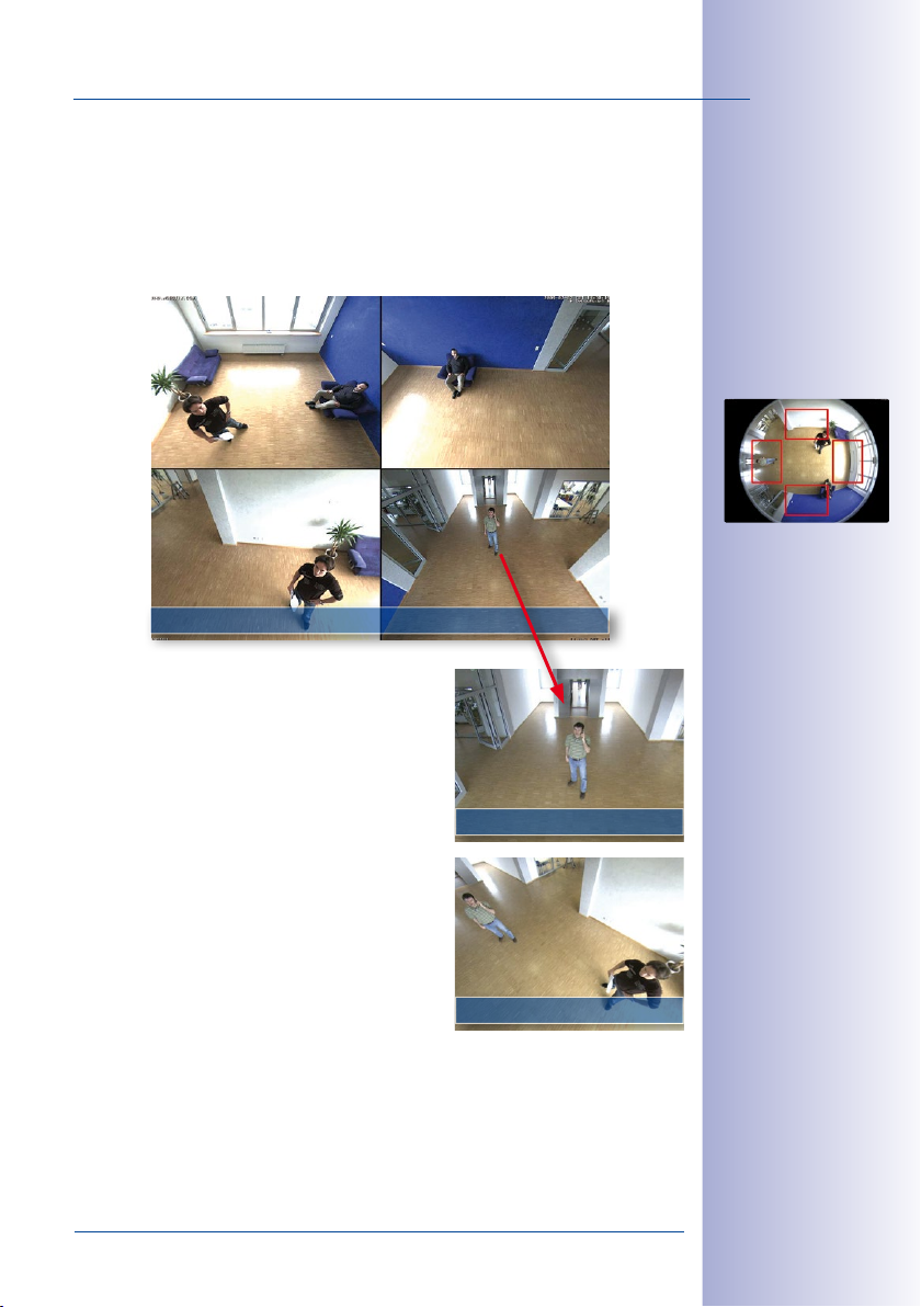
Surround View (Quad View), Based On The Correct Full Image
The Q24 “Surround” display mode replaces (when ceiling mounted) four cameras, and
shows four directions simultaneously on the monitor in a quad view. The preset North
position can be moved to any direction in the image; the camera generates the other
three directions (East, South, West) automatically and stores them as separate views.
25/164
North
West South
Surround View: Quad
Each of the four views features a software-controlled
pan/tilt/zoom function (virtual PTZ), allowing it to be
customized as necessary.
In order to reduce user workload, the Q24M can store
in addition to the North, East, South and West standard
views, a total of 256 user-defined camera views
using the vPTZ function, which can easily be brought
up using joystick keys or softbuttons. Besides being
able to manually bring up specific camera views, the
camera can also show them automatically by moving
through the North, East, South and West views or by
showing the first 16 saved camera views (one after
the other like in a slide show).
East
vPTZ & Zoom
Original Q24M image:
Each of the 4 views can
be individually modied
Original full image
vPTZ & Zoom
© MOBOTIX AG • Security-Vision-Systems • Made in Germany
www.mobotix.com • sales@mobotix.com
Page 26
26/164
Quick and easy navigation with a USB joystick
Q24M Camera Manual: Introduction
Virtual PTZ (vPTZ) – No Motor Required
The Q24M can zoom in on detail as well. These vPTZ functions are a standard feature in
the integrated Q24M camera software. The image from the hemispheric camera can be
enlarged using e.g. the mouse wheel, a joystick or a software-controlled PTZ panel,
and you can "move" the view to any section of the image. This provides the features
of a mechanical PTZ camera without the disadvantages of maintenance and
wear.
vPTZvPTZ
The vPTZ functionality works dierently depending on the camera operation platform
(web browser, MxEasy, MxControlCenter). Virtual zoom, pan and tilt using MxEasy and
MxControlCenter is very simple thanks to special software tools and the use of an optional
joystick. However, a joystick may also be used even with pure browser-based operation
from Internet Explorer (together with an ActiveX plug-in).
© MOBOTIX AG • Security-Vision-Systems • Made in Germany
www.mobotix.com • sales@mobotix.com
Page 27
Q24M Overview
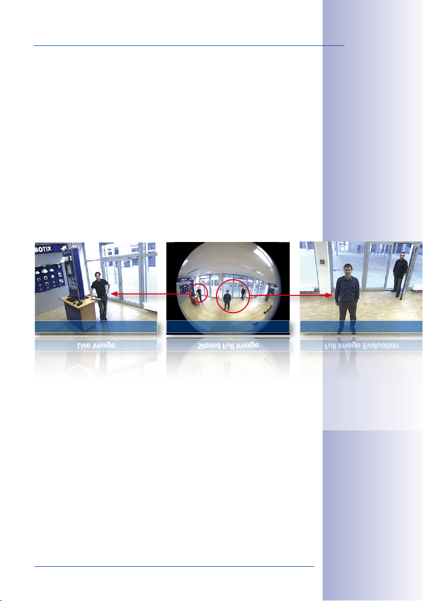
Live Image Stored Full Image Full Image Evaluation
Simultaneous Corrected Live Image And Full Image Recording
All conventional, motorized PTZ cameras only store the image that is currently viewed as
the live image (live image recording). This has one serious disadvantage as the record
ing can only show what has happened in the "visible" portion of the image; the rest is
lost and cannot be examined later on. For this reason, MOBOTIX has added the new full
image recording feature to the Q24M. This will not store the currently viewed image that
reflects the pan/tilt position and the zoom setting chosen by the user, but the full sensor
image - without vPTZ settings or image correction. When examining the recorded images,
the vPTZ features again come into play, as they allow zooming the visible image and use
the pan/tilt features to examine every corner of the recorded full image.
Example: The people marked by the red circle in the middle area of the image would
not have been recorded by a regular PTZ camera; the full image recording of the Q24M
allows to determine for example, the exact time at which the people entered the image
area recorded by the camera. A Browser (Internet Explorer with MxPEG ActiveX plug-in),
MxControlCenter or MxEasy can be used to examine the recorded sequences.
Live Image Stored Full Image Full Image Evaluation
27/164
-
Integrated vPTZ functions allow "analysis" of
the complete saved full
image at a later point
in time (in MxEasy and
MxControlCenter)
© MOBOTIX AG • Security-Vision-Systems • Made in Germany
www.mobotix.com • sales@mobotix.com
Page 28
28/164
The camera software is
responsible for image
correction, reducing
load on the user PC
Q24M Camera Manual: Introduction
Maximum Ease Of Use
The full image generated by the hemispherical lens (fisheye) can be dicult to evaluate.
MOBOTIX solves this problem with image distortion correction in the camera software that
displays perfectly corrected live images. The user PC does not experience any additional
load through this process, as image correction and generation of all desired image views
takes place in the camera itself. The result is that a large number of panoramic cameras
may be displayed simultaneously on a single PC.
Highly Ecient, Application-Oriented Image Transfer
While other camera systems must transport the full 3.1 megapixel image over the network
for further processing, a MOBOTIX camera will only transmit the desired image sections.
This means that a Q24M panorama image will only require a small part of the usual data
and bandwidth. Data from up to six times as many MOBOTIX cameras may be transported
over the same network compared to “standard” cameras.
Corrected image after
panorama correction
Economical bandwidth
usage due to smaller,
in-camera corrected
images (no loss of
image information)
Full image at 3.1 megapixels (2048 x 1536 pixels)
Panorama image at 0.6 megapixels (1280 x 480 pixels)
© MOBOTIX AG • Security-Vision-Systems • Made in Germany
www.mobotix.com • sales@mobotix.com
Page 29

Q24M Overview
Internal DVR
The Q24M secure models feature direct recording to integrated
MicroSD cards, which makes the camera fully independent of
any external storage media, even for longer periods of time. The
camera internally saves high-resolution video with sound, with
out requiring an external storage device or PC, and thus without
any network load whatsoever. Old recordings may be overwritten
automatically or automatically deleted after a specified period of
time. A 16GB MicroSD card, for example, allows the camera to
store more than a quarter million event images in VGA format
(640x480). For security reasons, the camera can even encrypt
the stored data.
Power failures are not an issue, as the video and image sequences remain safely stored
on the MicroSD card. Access to stored video sequences is possible at any time from the
camera user interface in the browser, MxControlCenter or MxEasy. If you would like to archive
sequences, you can store all of the data or only certain parts to a computer or a hard disk.
High Frame Rates Of Up To 30 fps
Like all other MOBOTIX cameras, the Q24M models can generate live video streams
with high frame rates and up to 3.1 megapixel image resolution (QXGA with 2048x1536
pixels). Up to 30fps are generated at megapixel resolution (1280x960 pixels). Even at
3.1 megapixel resolutions, the camera will still generate up to 20fps! Lip-synchronous
audio is transferred at all times.
Robust And Maintenance-Free
Thanks to its low power consumption of about 4 Watts and the total absence of mechanical
moving parts, the Q24M models feature the highest operating temperature range from
-30°C to +60°C (-22°F to +140°F). Both Q24M models (BASIC & SECURE) are absolutely dust
proof to IP54, with the SECURE model being resistant against water jets (IP65) also. Since
the cameras neither fog up nor require heating, power can be supplied all-year round
via the network cabling using standard PoE products.
-
29/164
4 GB MicroSD-card
already installed in the
camera (Q24M-Secure)
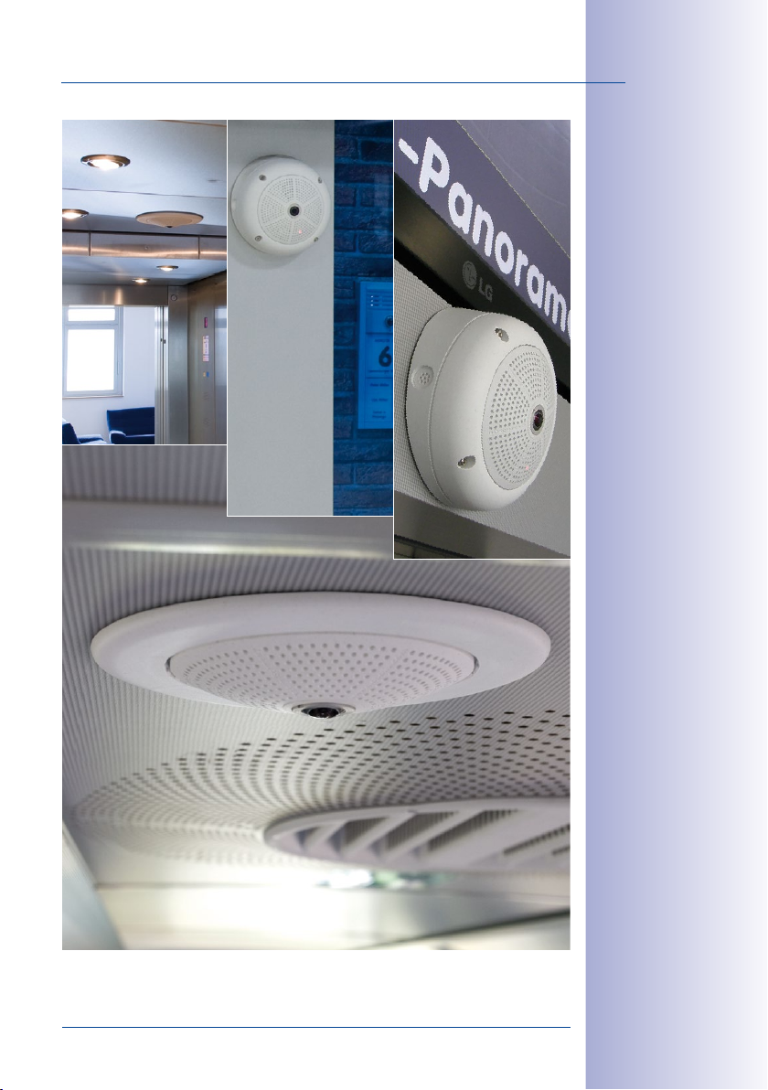
Camera Design Creates New Applications
Some application scenarios benefit from a surveillance camera that is present, but without
attracting attention. The low-key, elegant appearance of the camera, especially when
installed with the In-Ceiling set, makes the Q24M an optimum solution where discreet
design and an inconspicuous look are important. Hotels and restaurants present an
ideal example, but installations in public buildings, waiting rooms and showrooms are
also highly suitable.
© MOBOTIX AG • Security-Vision-Systems • Made in Germany
www.mobotix.com • sales@mobotix.com
Page 30
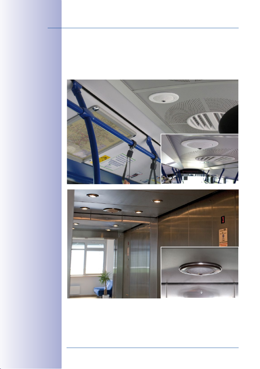
30/164
Q24M in the In-Ceiling
Set (local public
transport bus)
Q24M in the In-Ceiling
Set with stainless
steel ring (elevator)
Q24M Camera Manual: Introduction
The integrated DVR functionality with long-term storage on a MicroSD card also makes
the camera an ideal solution for mobile applications since it only requires a power sup
ply via the network cable (standard PoE) for full event-driven recording with video and
audio, thus delivering a complete standalone product. Application examples in this con
text are installations in public transportation such as busses, trains, aboard ships, airplanes,
etc.
-
-
Model Versions
The Q24M is available in Secure and Basic models, which come with dierent features.
Both models can also be ordered with an L22 Super Wide-Angle lens with a horizontal
image angle of 90°.
© MOBOTIX AG • Security-Vision-Systems • Made in Germany
www.mobotix.com • sales@mobotix.com
Page 31

Q24M– Next Generation Hemispheric Technology
1.2 Q24M– Next Generation Hemispheric Technology
The MOBOTIX Q24M is the tuned and optimized successor to the well-received
Q22M, introduced successfully in 2008. In one of the most renowned and com
petitive international design competitions, the MOBOTIX Hemispheric camera
was the first security and surveillance camera in the world to receive the red dot
award for product design (www.red-dot.org). The red dot is awarded to products
of exceptionally high quality design. The technical capabilities of the MOBOTIX Q24M also
make it an excellent choice. Above all, this performance is the result of the use of a new
microprocessor and modified system platform.
Significant Increase In Frame Rates (Up To 100 Percent)
Even 3.1 megapixel camera images may be transferred at a rate of 20 frames per second,
and megapixel images at up to 30 images per second.
User-Friendly Panorama Correction
In the standard "Panorama" view, the user may now switch between customized views
of the live image at the click of a button.
4 GB MicroSD Card
Every Q24M Secure is delivered at no extra charge with a high-quality, factory-installed
4 GB MicroSD card (internal DVR) as a standard feature – sucient for around 50,000
panorama images or 10 hours of HiRes video including audio (4frames/s).
Direct Camera Connection
The network cable and MiniUSB are easily connected over a newly developed and opti
mally sealed connector - without needing to open the camera housing - in the rear
casing of the camera.
-
31/164
-
Adjustable PoE Classes, 1 to 3
The desired PoE class of the camera may be raised or lowered from the default value of
2 to 1 or 3 from the camera software in the browser, to precisely adjust the functionality
of the camera and its accessories.
Only About 4 Watt Power Consumption
Despite the use of a more powerful processor, the power consumption of the Q24M is
maintained at the extremely low level of only about 4 watts.
© MOBOTIX AG • Security-Vision-Systems • Made in Germany
www.mobotix.com • sales@mobotix.com
Page 32

32/164
Q24M Camera Manual: Introduction
1.3 General MOBOTIX Camera Functions
Like all other MOBOTIX cameras, the Q24M models include a range of (software) func-
tions, such as video motion detection, long-term recording, alarm messaging and video
IP telephony, to name but a few. Unlike in camera systems from other manufacturers,
buying and installing additional software on the computer is unnecessary. Instead of
using a web browser, you can also download the free MxControlCenter software from
the MOBOTIX website, which allows quick displaying of multiple cameras on one monitor,
alarm switching with audio or an easy event search.
Camera vPTZ functions
may be controlled with
a mouse or joystick
Using a joystick: Internet
Explorer with activated
MxPEG ActiveX plugin, MxControlCenter
or MxEasy required
MxControlCenter and
MxEasy can be downloaded free-of-charge
at www.mobotix.com
vPTZ: Virtual Pan/Tilt/Zoom Features
While MxControlCenter has provided virtual PTZ features for some time now, these features
are now available directly via MOBOTIX camera. This means that you can continuously
zoom into or out of the live image using either the mouse wheel or a joystick. When storing
images or video sequences, you can choose to store either the visible image area of the
live image or the full sensor image (full image storage). This also allows you to examine
parts of an image or video that had not been visible in the live image section on display
at the time of the recording.
Automatic Image Correction
Another problem familiar from the field of photography are the distortions that result from
using wide-angle lenses. Straight lines near the image borders are bent outwards. The
integrated distortion correction features of the camera (and of MxControlCenter) allow
correcting the curve of various lenses using software algorithms.
Live Video With Up To 30 fps, Including Audio
MOBOTIX cameras deliver smooth live video with lip-synchronous audio, yet they keep
network load to a minimum. Some analog systems may also be able to do this, but the
recording quality is much higher with MOBOTIX since the cameras eciently store the
high, live image resolution and frame rate without compromising image quality. MOBOTIX
technology thus provides for continuous recording of simultaneous video from 30 cameras
at 30 frames per second each, including audio, all on one standard PC.
Low Bandwidth Requirements
MOBOTIX' patent pending MxPEG streaming format allows fast live video with audio
at extremely low network load (1 to 2Mbps). Since the MOBOTIX camera itself detects
movements in the image (and not the computer), video sequences are only transmitted
if movements occur.
Voice Over IP
Moreover, MxPEG provides for lip-synchronous live audio and two-way communication
between the camera and a computer. Room surveillance is possible using a browser
(Internet Explorer), MxControlCenter or MxEasy. Customized alarm notification on your
mobile or via Internet telephony is just as easy as event-controlled voice messages directly
from the camera.
© MOBOTIX AG • Security-Vision-Systems • Made in Germany
www.mobotix.com • sales@mobotix.com
Page 33

General MOBOTIX Camera Functions
Internet Telephony (SIP) And Video SIP
Video SIP allows establishing audio/video
connections to the camera using Windows
Messenger or similar applications (e.g.
CounterPath X-Lite/Eyebeam). This feature also
allows the camera to be remote controlled using
the phone keys, the camera itself can place
phone calls in case of alarms.
Long-Term Storage On File Servers Included
MOBOTIX cameras have an integrated long-term storage system for Linux, Windows and
Mac OS X computers. Every camera manages its own ring buer storage on the shared
folder. Thanks to this decentralized approach, 30 live cameras can store images of up to
30 frames per second each, including audio, on a single computer.
Internal DVR: Storage on MicroSD Or CF Cards
MOBOTIX cameras support direct storage on an internal MicroSD/SD/CF card (basic models
excluded). By using this integrated flash card DVR, the camera is able to oer the following
additional applications:
•
Stand-alone use of the camera without a file server by recording to the MicroSD card.
• High-security application with recording on a file server or NAS/SAN in which the
SD card serves as storage buer. It can thus bridge longer network or file server
failures without losing any video sequences (supported in a future software version).
• Event downloads from the MicroSD card for evaluation of the recorded sequences
on a computer.
Internal DVR External USB Storage Remarks for USB Storage
M12 optional optional Adapter cable required
D12 optional optional Adapter cable required
V12 optional - -
M24M included optional
D24M included optional Adapter cable required
Q24M included optional Adapter cable required
Device can be connected directly
33/164
Internal DVR is either
an option during order
placement (e.g. M12
R8) or upgradeable
later with an SD card
A 4 GB MicroSD card
is included with the
Q24M Secure
© MOBOTIX AG • Security-Vision-Systems • Made in Germany
www.mobotix.com • sales@mobotix.com
Page 34

34/164
No heating required
- PoE is no problem
even in winter
Q24M Camera Manual: Introduction
Event And Time-Controlled
Just like triggering event-controlled recording upon detecting movements in the image,
the camera can also record when the volume detected by the microphone exceeds a
certain trigger value. Using scheduled daily recording, time tasks can start or stop video
recording, upload images to a web site or send e-mails with video/audio clips. Vacation
times and holidays can be programmed.
Remote Alerting
In case of an alarm, MOBOTIX cameras automatically pop up windows or activate other
functions at a remote security control center. The cameras can use network/wireless,
GSM/GPRS/UMTS (3G) or Internet connections for this purpose.
Integrated Power-over-Ethernet
Power is supplied as Power over Ethernet via the network cabling using the MOBOTIX NPA-
PoE-Set or from a PoE compatible switch (both according to the IEEE 802.3af PoE Standard).
Caution
Previous MOBOTIX network power accessories such as the NPA Set, Power Box
and Power Rack (MX-NPA-Set, MX-NPR-4 and MX-NPR8/20) are not suitable for
use with the Q24M.
No heating is necessary thanks to the well-insulated plastic housing and anti-fogging
properties. Due to their low power consumption (approx 4.5 watts), MOBOTIX cameras,
unlike those of other manufacturers, may be operated both indoors and outdoors using
a PoE power supply.
Logo generator for
display of graphics
already integrated
in the live image
Logos, Animated Or Freestyle
The MOBOTIX camera logo generator allows time-scheduled banners and graphics (including
files loaded automatically from any URL) to be integrated into current camera. MOBOTIX
cameras are the only network IP cameras supporting animated and transparent graphics.
© MOBOTIX AG • Security-Vision-Systems • Made in Germany
www.mobotix.com • sales@mobotix.com
Page 35

General MOBOTIX Camera Functions
30 Cameras Live Using MxControlCenter
Instead of using a web browser, you can also download the free-of-charge MxControlCenter
from www.mobotix.com, which allows fast display of up to 30 MOBOTIX cameras on one
monitor. In addition, MxControlCenter can process incoming alarms with sound from the
cameras and allows comfortable search and evaluation of alarm video clips (including
audio). The integrated Layout Editor of MxControlCenter allows you to quickly create floor
plans by simply dragging/dropping the cameras onto a background image. Load a floor
plan as background image, drag & drop the cameras; done.
MxEasy – Intuitive Application For Windows, Macintosh And Linux
The new MOBOTIX MxEasy aims at easy operation of the most important camera functions
through its intuitive user interface, thus creating a new user experience when viewing and
controlling MOBOTIX cameras. The clear design allows management of up to 16 cameras,
and the application can show up to four cameras at the same time.
35/164
Management of several hundred cameras
on one standard PC
Free download at
www.mobotix.com
No license fees
free updates
For up to 16
MOBOTIX cameras
© MOBOTIX AG • Security-Vision-Systems • Made in Germany
www.mobotix.com • sales@mobotix.com
Free download at
www.mobotix.com
No license fees
free updates
Page 36

36/164
Q24M Camera Manual: Introduction
All settings selected in MxEasy (e.g. virtual camera position, zoom, brightness, volume,
microphone sensitivity, image storage, signal outputs) are usable immediately and are
stored instantly in the configuration of the corresponding camera. The calendar function
integrated in the Alarm Planner provides
access to innovative features for scheduled
settings of one or more cameras.
For the first time, this tool not only controls
video and audio recording based on certain
time and date information, but also allows
activating/deactivating features like video
motion detection, image brightness and
the microphone based on a date and time
schedule.
MxEasy is available as a free-of-charge download for MS Windows and Mac OS X operat
ing systems under www.mobotix.com. A Linux version will be available soon.
Diverse Installation Options
Not only can MOBOTIX cameras be installed under almost all weather and temperature
conditions, they also oer suitable installation materials from a wide range of accessories
for any conceivable application scenario.
Additional Camera Functions (Software)
• True software scaling to easily generate smaller image formats for PDAs (such as
320x240, 160x120, etc.).
• Audio video recording with three dierent recording modes: event recording with
audio, continuous recording with variable frame rate and audio as well as eventcontrolled snapshot recording of JPEG images.
• Storage failure detection can monitor a file server (or a flash device) and can use
one or more of the defined messaging options for error notification.
• Player of recorded images/video sequences with audio in the integrated video
management system.
• Multiwatcher screen can display and monitor several cameras over the Internet,
with only one camera requiring access from the outside. This "proxy" camera uses
only very little bandwidth, making it an ideal solution for low-bandwidth connections.
•
MultiView screen for displaying multiple cameras or events in one browser window.
• Event notification by e-mail, SMS (using a provider), voice notification (Phone Call-
Out), sounds and by visual means (e.g. red frame in live image) using two separate
messaging paths.
• Object tracing for analyzing the paths of objects that are moving in the image.
• Time Tables with handling of customized holidays and vacations. The time tables
are used to control the camera's arming, image recording messaging, logos, the
obscure image function as well as other features.
-
© MOBOTIX AG • Security-Vision-Systems • Made in Germany
www.mobotix.com • sales@mobotix.com
Page 37

General MOBOTIX Camera Functions
• Remote signaling for master/slave cameras, with the master camera controlling
the arming status of the slave cameras. This allows arming, for example, of all slave
cameras using a key switch connected to the master camera.
• Transfer profiles for comfortably controlling transmissions via FTP, e-mail, phone
calls and network messages.
• Speakerphone* with speak, listen and intercom modes using the microphone and
speaker.
• Phone Call-In* to remotely control the camera using a touchtone telephone
(retrieve camera information, establish an Internet connection, announce the retrieved
IP address, intercom feature, etc.).
• MxPEG video compression using MxControlCenter. The ActiveX plug-in for Internet
Explorer users brings all advantages of MxPEG to the browser-based user interface
(including the audio stream to and from the camera).
• Routing allows use of other network connections besides the standard route.
• DynDNS client for accessing the camera via the Web using a symbolic name (e.g.
mymobotixcam.dyndns.org), despite the provider assigning a new dynamic IP address
every time the camera connects to the Internet.
• None-voidable backup system starts the cameras in the original operating state
if a software update fails, allowing the user to easily restart the update process.
•
Enhanced startup options for the camera (obtain IP address via DHCP, announcement
of IP address and other network data, reset to factory default settings).
• Notifications upon errors or when rebooting provide a method for executing one
or more notifications (e.g. blinking of the camera LEDs, audio message, FTP, e-mail,
phone call, network message).
• Extended security features protect the pages and features of the camera and
prohibit unauthorized access (IP-level access control, intrusion detection). They also
provide SSL-protected transmission of the video sequences and the data (using SSL
encryption and X.509 certificates).
37/164
* Telephony features
using VoIP connections
(internet telephony)
Free Software Updates (www.mobotix.com)
MOBOTIX provides software updates free-of-charge at regular intervals that improve
and expand the camera’s functionalities. Chapter6,
provides more information on the process.
Manual
Software Update
, in the
Software
© MOBOTIX AG • Security-Vision-Systems • Made in Germany
www.mobotix.com • sales@mobotix.com
Free-of-charge software updates from
www.mobotix.com
Page 38

38/164
Q24M Camera Manual: Introduction
1.4 Lens Options, Hardware And Software Features
MOBOTIX Q24M cameras come with a standard L11 fisheye lens with a 180° horizontal
image angle. The camera is also available with an L22 Super Wide-Angle lens with a
horizontal image angle of 90°. The integrated virtual PTZ features of the camera software
or MxControlCenter/MxEasy properly correct the lens distortion that is specific to each of
the lenses. Both lenses deliver good image quality even when using maximum digital
zoom. Since MOBOTIX cameras are backlight-proof, they do not require a mechanical
auto iris, making them extremely robust and maintenance free.
Full image with L11 180° fisheye in public transit bus
Corrected normal image with L11 180° fisheye in vPTZ mode
© MOBOTIX AG • Security-Vision-Systems • Made in Germany
www.mobotix.com • sales@mobotix.com
Page 39

Lens Options, Hardware And Software Features
Lens Table L11 L22
Original image
35mm equivalent focal length 11mm (0.43 in) 22mm (0.87 in)
Actual focal length 1,8mm (0.07 in) 4mm (0.16 in)
Aperture 2.0 2.0
Horizontal image angle 180° 90°
Vertical image angle 160° 67°
Distance 1 m (1.09 yd): m m
Image width infinite 2.0
Image height 11 1.3
Distance 3 m (3.28 yd): m m
Image width infinite 10.0
Image height 55 6.6
Distance 10 m (10.94 yd): m m
Image width infinite 20.0
Image height 110 13.3
Distance 20 m (21.88 yd): m m
Image width infinite 40.0
Image height 220 26.6
39/164
Notes
The specified focal lengths of MOBOTIX lenses do not reflect the actual focal length
xx
of the lenses, but the focal length (L
mm) converted to 35mm camera format. For
example, the MOBOTIX Super Wide-Angle lens has an actual focal length of 4mm. This
would be the equivalent of 22mm on a 35mm camera. This lens is thus called
Converting the focal lengths to 35mm camera as a known format provides for bet
ter comparison of the image formats and the image angles of the dierent lenses.
Another benefit is that you can easily set any average 35mm camera (analog or
xx
digital) to the same focal length as the MOBOTIX lens (L
) to obtain the same image
angle. This approach greatly facilitates lens selection.
© MOBOTIX AG • Security-Vision-Systems • Made in Germany
www.mobotix.com • sales@mobotix.com
L22
Stated focal lengths of
MOBOTIX cameras are
given with reference
to a 35 mm camera
.
-
Page 40

40/164
Q24M Camera Manual: Introduction
*Special MiniUSB
adaptor cable available as an accessory
**A 4 GB MicroSD
card is included with all
Q24M Secure models,
MicroSD cards of up
to 64 GB may be used
MX-Q24Mi-Basic-D11
Q24Mi-Basic D11
Q24M Hardware Features
Outdoor weatherproof IP54 IP54 IP65 IP65
Ethernet/ISDN/USB/RS232 E /- / - /- E /- / - /- E /- / U*/- E /- / U*/-
MicroSD slots - - 1 1
Integrated microphone/speaker -/X -/X X/X X/X
Mono (M) / Dual (D) M M M M
Image Sensor Color Color Color Color
Lens L11 L22 L11 L22
Resolution VGA VGA 3 MEGA 3 MEGA
Resolution horizontal x vertical 640x480 640x480 2048x1536 2048x1536
Max. frame rate CIF/VGA/MEGA/3MEGA (fps)
Sensitivity at 1/60 second (lux) 1 1 1 1
Sensitivity at 1 second (lux) 0.05 0.05 0.05 0.05
RAM Storage (MB) 64 64 128 128
Temp. video storage, ring buer (MB) 2 2 64 64
Internal DVR (MicroSD card), ring buer (GB)** - - up to 32 up to 32
• CIF images (for 32 GB int. DVR), approx.
• VGA images (for 32 GB int. DVR), approx.
• MEGA images (for 32 GB int. DVR), approx.
• 3 MEGA images (for 32 GB int. DVR), approx.
External audio (Line-In/Out) - - - -
Signal input pins - - - -
Signal outputs - - - -
Concealed cabling X X X X
Q24M Software Features
Digital zoom (continuous) with panning X - X X
Panorama and surround views X - X -
Additional storable views X - X X
Full image recording - - X X
16/16/-/- 16/16/-/-
- - 2 mil. 2 mil.
- - 1 mil. 1 mil.
- - 350,000 350,000
- - 160,000 160,000
MX-Q24Mi-Basic-D22
Q24Mi-Basic D22
MX-Q24M-Sec-D11
Q24M-Secure D11
30/30/30/20 30/30/30/20
MX-Q24M-Sec-D22
Q24M-Secure D22
© MOBOTIX AG • Security-Vision-Systems • Made in Germany
www.mobotix.com • sales@mobotix.com
Page 41

Lens Options, Hardware And Software Features
Q24M
41/164
M12
D12
D24M
M24M
Software Features (All Models)
Digital zoom (continuous) with panning
Motion JPEG/MxPEG video streaming
Custom exposure windows
Video Motion detection
Time and event control (FTP, email, logos)
Weekly schedules/holidays
Web functionality (FTP, email)
Quad/MultiView in browser
Recording/Playback in browser
Logo generator, animated
Single image recording (pre-/post-alarm images)
Terabyte ring buer (Win/Lin/Mac) via network
Continuous video/audio recording, 0.2 to 30 fps
Video/audio recording (event-triggered)
Event-controlled frame rate with continuous audio
Flexible event logic
Master/Slave arming by one camera
Time-scheduled privacy zones, several areas
Bidirectional audio (IP) from/to browser
Customized voice messages
VoIP telephony (Audio/Video, SIP)
Alarm calls to softphones (SIP) e.g. X-Lite
Remote alarm notification (via TCP/IP, IP Notify)
RS232 Data Logger/Terminal
Programming interface/HTTP API
Security features (HTTPS/SSL, IP-level access
control, network authentication IEEE 802.1X)
Model Feature List
Image size
Image Sensor
Standard lens for software version
Audio support (Microphone/Speaker)
Basic Model
Web Model
IT Model
X* X X X
X/X X/X X/X X/X
X X X X
X X X X
X X X X
- X X X
X X X X
X X X X
X X X X
- X X X
3 3 10 50
- - X X
- - X X
- - X X
- - X X
- - - X
- - - X
- - - X
- - X** X**
- - X X
- - X** X**
- - X X
- - X X
- - X*** X***
- - X X
X X X X
VGA 3 Mega VGA 3 Mega
Color Color
Color & B/W
Color & B/W
L22 L22 L22 L22
-/L** -/L** M/L** M/L**
Secure Model
The Web version is only
available for the M12
The Basic version is
only available for the
D24M and Q24M
The IT version is not
available for the Q24M
*Only available for Q24M
**D24M IT and Secure
models allow connecting an external speaker
and microphone. D24M
cameras are not delivered with a microphone and speaker.
***RS232 only
for M12/D12
SW image sensors with
megapixel resolution
(1280x960 pixels)
M12 lens included if
requested by customer
© MOBOTIX AG • Security-Vision-Systems • Made in Germany
www.mobotix.com • sales@mobotix.com
Page 42

42/164
Wall installation with
On-Wall Set 10°
Q24M Camera Manual: Installation
2 INSTALLATION
The Q24M is primarily designed for installation on walls or ceilings. The supplied L11 180°
lens captures the entire room, practically from wall to wall and from floor to the ceiling.
See sections 2.4 and above. for the dierent installation options; drilling templates can
be found at the end of the manual.
2.1 Preparing The Installation
Before mounting the MOBOTIX Q24M, the following questions should be answered:
1. Where will the camera be mounted?
Mounting to a ceiling or wall; section 2.1.1. and 2.1.2
2. Which other mounting options are available?
On-wall mounting, in-ceiling mounting, vandalism protection, wall mounting, pole
mounting, see section2.1.3
3. How is the camera connected to network and how is power supplied?
MX-NPA-PoE or other PoE components (IEEE 802.3af), see section2.1.4
4. How are the connections furnished from the building?
Wall outlets, see section2.1.5
5. What cabling considerations are necessary?
Wiring, see section2.1.6 and 2.11
The following sections contain a brief answer to each of these questions, as well as refer
ences to the relevant sections in this manual. For more information on the MOBOTIX Q24M
and available accessories, please see: www.mobotix.com
-
© MOBOTIX AG • Security-Vision-Systems • Made in Germany
www.mobotix.com • sales@mobotix.com
Page 43

Preparing The Installation
2.1.1 Wall-Mounted
To make optimal use of the high-resolution 180° panorama functionality of the Q24M, the
camera must be mounted on an internal or external wall. The entire hemisphere of the
room directly in front of the camera is then eectively monitored, from the wall on the left
of the camera to the wall on the right. Corresponding fine-tuning in the user interface
software allows the displayed panorama image to be adjusted to dierent practical appli
cations (see section 3.3).
43/164
-
Wall installation with
On-Wall Set 10°
The camera should
preferably be mounted in
the middle of the room
to be monitored using
the 10° On-Wall Set
The Q24M Panorama: one camera - three simultaneous views
High-resolution 180° panorama
Virtual PTZ 1 Virtual PTZ 2
© MOBOTIX AG • Security-Vision-Systems • Made in Germany
www.mobotix.com • sales@mobotix.com
Original image from the
camera shown above using
the 10° On-Wall Set
(Panorama Focus View)
Page 44

44/164
Q24M Camera Manual: Installation
Selecting An Appropriate Camera Position
The Q24M is primarily suited to providing an excellent overview, and less suitable for
more exact details. For active operation, the camera should be mounted at a (out of
direct reach) height ranging from 2.5 to 3.5 m. People, for example, may be identified
very well at distances of up to 1.5m, and with sucient detail at up to 3m. Objects can
be recognized even at distances of 5 m and more from the camera. During installation,
ensure that the camera is focused on the most important areas of the room as directly
as possible, in order to provide the desired level of detail recognition. For wall installation,
use of the 10° On-Wall Set is ideal in many cases.
Camera focus (best image quality) - standard installation
Identification Recognition Perception
Wall Mount: Mounting
the camera in the
middle of the wall
The OBEN / TOP label
is only visible when the
outer shell is removed
Mounting in the middle of the wall
Hint: The Q24M should always be installed on a wall such that the arrow on the camera
housing marked OBEN / TOP points towards the ceiling of the room.
© MOBOTIX AG • Security-Vision-Systems • Made in Germany
www.mobotix.com • sales@mobotix.com
Page 45

Preparing The Installation
Wall Installation With The 10° On-Wall Set For Image Optimization
An on-wall set, available as an accessory in 0° and 10° inclinations, may also be used for
installation. While the 0° set primarily oers easier installation and more storage space
for cables and add-on modules (WLAN, connectors, etc.), the 10° set may also increase
the image quality in certain cases. In particular for wall installations which must be carried
out at greater heights for technical or other reasons (over doors, windows, etc.,) adding
a slight tilt to the camera, and thus also the lens, will return better results, as the center
of the lens is then focused more directly on the center of activity in the room (optimal
utilization of lens capabilities).
Camera focus (best image quality) - optimized with 10° On-Wall Set
Wall Mounting Over A Wall Outlet
Professional wall or ceiling installation of a Q24M is generally possible without accessories.
However, due to elevation of the rear casing of the camera caused by connections and
holders, a wall outlet should be installed prior to camera installation (see drilling template
Q24M). This provides perfect protection to the cabling, ensuring that it cannot be seen or
damaged from outside.
45/164
Optimized image quality
through wall installation
with On-Wall Set 10°
© MOBOTIX AG • Security-Vision-Systems • Made in Germany
www.mobotix.com • sales@mobotix.com
Page 46

46/164
Discreet ceiling
installation using the
In-Ceiling Set
Q24M Camera Manual: Installation
2.1.2 Ceiling-Mounted
Thanks to its hemispherical lens, a single Q24M can monitor an entire room right into
each of the four corners (360° Panorama View). The camera's should ideally be posi
tioned on the ceiling in the center of the room. Due to its inherent physical and optical
properties, the precision of the lens
decreases as the distance from the
lens grows. This means that the
maximum usable image area varies
greatly depending on the intended
purpose of the camera. Rooms with
a square floor area of up to approx.
40m² in general allow recognizing
details even at the borders of the
full image. If you would only like to
know if persons enter a room, or
to monitor specific objects, rooms
of up to 100m² floor area can be
monitored using a single Q24M.
Outdoors, the Q24M is usually mounted on a building wall, corner or pole instead of the
ceiling. For this situation, we recommend the use of the practical wall mount from the
range of accessory products (section 2.8) or an extension.
The image quality (precision) diminishes as the
distance of an object to the camera focus point
increases: 1 very good, 2 good, 3 satisfactory
-
© MOBOTIX AG • Security-Vision-Systems • Made in Germany
www.mobotix.com • sales@mobotix.com
Page 47

Preparing The Installation
Non-Square Rooms
When viewing a 360° (full) image in the browser, you will notice that the top and bottom
of the image is not fully visible, i.e. some image information has been clipped. This is not
a fault of the camera, but intended behavior that aims at achieving the best possible
utilization of the image sensor by the camera software. Bearing this in mind, it is advisable
to install the Q24M in rectangular room ceilings so that the arrow marked OBEN/ TOP
points towards one of the longer walls of the room as shown in the figure.
47/164
Original full image
from the Q24M (ceiling installation in a
rectangular room)
© MOBOTIX AG • Security-Vision-Systems • Made in Germany
www.mobotix.com • sales@mobotix.com
Page 48

48/164
Q24M Camera Manual: Installation
Never mount the camera to metal surfaces
(condensation may
damage the camera):
MOBOTIX recommends
using an On-Wall Mount
or the Wall Mount
Lowered Mounting Or Mounting On Extensions
When mounting the camera in rooms with a
high ceiling , or outdoors, it may be advisable
to mount the camera in a lower position. This
reduces the distance between the camera and
the objects that are to be monitored, which in
turn increases the recognizability of details.
One practical solution would be to install the
camera on a base plate attached to a suitable
extension (metal tube) hanging from the ceiling. The network cable can be hidden from
view by running through the interior of the tube.
Similar to lowered mounting from the ceiling,
you can also attach the camera to an extension
mounted to a wall to better use the 360° image
of the camera (e.g. outside, above a portal).
Such an installation would use the pole mount
accessory (MX-D22-OPT-MH) in conjunction
with the wall mount (MX-D22-OPT-WH) as a
sturdy base for the camera, which is then
mounted to the extension pole.
MOBOTIX does not recommend attaching the
camera directly to metal carriers, especially
when mounting the camera outdoors or when
the ambient temperature varies greatly. As
an additional measure to protect the camera
against condensation, you should use either
the On-Wall set (MX-D22-OPT-AP) or the Wall
Mount (MX-D22-OPT-WH).
For the installation
on building corners,
the Corner and Pole
Mount and a Wall
Mount will be needed
Installation On Building Corners With The Corner And Pole Mount
This is a special method of Q24M installation, oering
substantial advantages for the outdoor surveillance
of buildings.
The hemispherical lens of a single Q24M can cover
the entire 270° range from one building wall to the
other, for an "around the corner" view!
© MOBOTIX AG • Security-Vision-Systems • Made in Germany
www.mobotix.com • sales@mobotix.com
Page 49

Preparing The Installation
2.1.3 Mounting Options
On-Wall Installation (MX-OPT-AP)
The On-Wall Set can reliably protect external cables if the cables cannot
be fed in the center below the camera housing. The On-Wall mount
also provides ample space for extra modules.
On-Wall Installation With 10° Inclination (MX-OPT-AP-10DEG)
This On-Wall Set is identical to the regular On-Wall Set, except that
the mounted camera is tilted by 10 degrees. The inclination makes it
possible for the camera to deliver the best images even in demand
ing situations.
In-Ceiling Installation (MX-OPT-IC)
The In-Ceiling Set allows the Q24M camera to be installed in suspended
ceilings, for example. This type of installation provides optimum protection for the camera and reduces the visible profile to a minimum,
since the camera only protrudes 24mm from the ceiling.
Vandalism Set (MX-Q24M-OPT-VANDAL)
The Vandalism Set provides added protection for Q24M cameras. The
set consists of a robust stainless steel cover (matt or polished) and
an impact-resistant polycarbonate dome. A camera equipped with
the Vandalism Set is perfectly suited for applications in demanding
environments (such as prisons, trouble areas, train stations, etc.).
-
49/164
On-Wall Set (IP65, for
outdoor applications)
On-Wall Set 10° (IP65,
for outdoor applications)
Discreet in-ceiling
installation; decorative
outer ring also available in stainless steel
Vandalism Set (IP65)
Wall Mount (MX-OPT-WH)
The Q24M/D24M Wall Mount is the ideal solution for mounting the
Q24M to walls for indoor and outdoor applications. The camera is
absolutely dustproof and resistant against water jets (IP65). The wall
mount also covers RJ45 wall outlets and has ample space for addi
-
tional modules.
Corner And Pole Mount (MX-OPT-MH)
The MOBOTIX Corner and Pole Mount is the ideal choice when mounting the MOBOTIX Q24M to a pole or building corner (Panorama View
covering approx 270°). This mount can only be used in conjunction with
the wall mount. For poles with a diameter ranging from 60 to 180 mm.
© MOBOTIX AG • Security-Vision-Systems • Made in Germany
www.mobotix.com • sales@mobotix.com
Wall Mount made from
sturdy PBT-30GF (IP65)
Outdoor Corner and Pole
Mount made from stainless steel (in conjunction with Wall Mount)
Page 50

50/164
The Q24M supports the Power over
Ethernet standard
IEEE 802.3af (PoE)
Q24M Camera Manual: Installation
2.1.4 Network Connection And Power Supply, UPS
Power over Ethernet (PoE Conforming To IEEE 802.3af)
All Q24M models are supplied with power using the PoE standard. The Network Power
Adapter (MX-NPA-PoE-Set) may be used for smaller installations. For larger installations,
it is worth investing in a PoE capable supply device available on the market.
The Network Power
Adapter replaces the
crossover cable when
directly connecting to a computer
Only use the new (blue)
MX-NPA-PoE set
for the Q24M - the
MOBOTIX Network
Power accessories NPASet, Power-Box, and
Power-Rack (MX-NPASet, MX-NPR-4
and MX-NPR8/20)
are not compatible
with the Q24M
PC or POWER
LAN or POWER
Network Power Adapter
MX-NPA-PoE
CAMERA
Caution
The maximum length of the network cable for power supply over an Ethernet cable
is 100m/328ft.
Previous MOBOTIX network power accessories such as the NPA Set, Power Box
and Power Rack (MX-NPA-Set, MX-NPR-4 and MX-NPR8/20) are not suitable for
use with the Q24M.
Note
The MOBOTIX Q24M can be powered by switches or routers which support the PoE
(Power-over-Ethernet) standard and conform to IEEE 802.3af.
Sections 2.11 and higher contain more information on the possible combinations of
connecting the Q24M and power supply options.
Advantages of PoE power supply:
• Allows setting up centralized backup power supply via the network.
• Reduces energy consumption.
• No extra network connection for camera required.
© MOBOTIX AG • Security-Vision-Systems • Made in Germany
www.mobotix.com • sales@mobotix.com
Page 51

Preparing The Installation
Using Uninterruptible Power Supplies (UPS)
In order to maintain a continuous power supply even when utility power fails, you should
install an uninterruptible power supply (UPS). These devices also provide full protection
against electrical surges and voltage fluctuations and thus enhance the reliability of the
system as a whole.
When using a more powerful 19" rack-mounted UPS, you can also protect all other network
components (e.g. switches, routers, PoE switches, etc.).
Since MOBOTIX cameras do not require any heating (even during winter), the average
power consumption of approximately 4.5 W is very low. This in turn means that you can
centralize the UPS-protected power supply by injecting power into the network cables
(max. 100m). This kind of protected power supply can be used either with MOBOTIX PoE
products (MX-NPA-PoE + Universal Power Supply) or with PoE-compliant switches accord
ing to IEEE 802.3af.
51/164
UPS not only protect
the camera against
power failures, they also
protect all other connected network devices
against damage from
voltage peaks and lows
-
19" system with UPS
MOBOTIX NPR or
PoE switch
PC/Server
Raid
UPS
2.1.5 Preparing The Camera Connections, Wall Outlets
Once the camera position, the position of the cable outlets and the method of power supply have been decided upon, the cabling can be installed. Before mounting the MOBOTIX
Q24M, you should make sure that the network connections have been properly tested to
ensure that the camera functions correctly when it is installed.
© MOBOTIX AG • Security-Vision-Systems • Made in Germany
www.mobotix.com • sales@mobotix.com
PoE power supply of the
cameras allows using one
UPS over the network
(enhanced security)
Page 52

52/164
Q24M Camera Manual: Installation
2.1.6 Wiring, Fire Prevention, Lightning And Surge Protection
When installing the wiring inside or outside of buildings, make sure you always adhere
to the relevant regulations on wiring, fire prevention and protection against lightning.:
MOBOTIX cameras are protected against the eects of small electrical surges by a range
of measures. These measures, however, cannot prevent the camera from being damaged
when stronger electrical surges occur. Particular care should be taken when installing the
camera outside to ensure proper protection against lightning, as this also protects the
building and the entire network infrastructure.
MOBOTIX recommends having MOBOTIX cameras installed only by certified specialists
accustomed to installing network devices and having proper respect for the applicable
regulations regarding lightning protection and fire prevention as well as the current tech
nology for preventing damages from electrical surges.
Wiring
When installing the wiring, make sure to follow these guidelines:
•
Data cable: Make sure you only use double-shielded CAT5
or higher cable (S/STP) for Ethernet connections.
• Outdoors: Installing the camera outdoors requires special
precautions and measures regarding the cables as well
as lightning and surge protection (see below).
• Wire lengths: The cable segments must not exceed the
maximum allowed cable lengths in order to ensure proper
data transfer (see section 2.11).
• Avoiding induction: When running data cables parallel to existing regular power
lines or high-voltage wires, make sure you observe the minimum distances to the
power cables.
-
Fire Prevention
When installing the power lines to the camera, make sure you always adhere to the
country-specific regulations (e.g. VDE in Germany, IEEE in the USA) in eect on wiring and
fire prevention at the site of the installation.
© MOBOTIX AG • Security-Vision-Systems • Made in Germany
www.mobotix.com • sales@mobotix.com
Page 53

Preparing The Installation
Lightning And Surge Protection
More information is available at an institution such as the International Electrotechnical
Commission (IEC, www.iec.ch) or at a manufacturer of protection devices against lightning
and electrical surges, such as Dehn (www.dehn.de).
53/164
© MOBOTIX AG • Security-Vision-Systems • Made in Germany
www.mobotix.com • sales@mobotix.com
Page 54

54/164
Q24M Camera Manual: Installation
2.2 Q24M Basic/Secure: Delivered Parts, Components, Dimensions
2.2.1 Delivered Parts And Camera Components
*MicroSD card only available for Q24M Secure
Item Quantity Part Name
1.1 1 Camera
1.2 1 Lens
1.3 1 Lens wrench
1.4 1 MicroSD card (4 GB)*, pre-installed
1.5 1 CAT5 patch cable, 0.5m incl. washer, pre-installed
1.6 1 Allen wrench 3mm
1.7 1 Allen wrench 2mm
1.8 1 Torx wrench
1.9 1 Outer shell
1.10 1 Mounting ring
1.11 4 Universal screw anchors 8 mm
1.12 4 Stainless steel washers Ø 5,3mm
1.13 4 Stainless steel wood screws with hex head 4.5x60mm
1.14 4 Stainless steel Allen screws M4x16 mm
1.15 4 Stainless steel washers Ø 4.3mm
1.16 2 Cable retainer with bayonet catch (patch cable, MiniUSB)
© MOBOTIX AG • Security-Vision-Systems • Made in Germany
www.mobotix.com • sales@mobotix.com
Page 55

Q24M Basic/Secure: Delivered Parts, Components, Dimensions
Lens unit
Speaker
Microphone
(only Q24M-Sec)
LEDs
Slot for MicroSD card
(not externally accessible)
MiniUSB (e.g. ExtIO)
Bayonet catch
Network connector
MxBus (for future
enhancements)
R key
2.2.2 Camera Housing And Connectors
The MOBOTIX Q24M consists of the camera housing (motherboard and lens), the outer
shell and the mounting ring.
Connections
• NET (Ethernet network incl. PoE power supply)
• MiniUSB (e.g. for ExtIO)
• Slot for MicroSD card
55/164
L key
© MOBOTIX AG • Security-Vision-Systems • Made in Germany
www.mobotix.com • sales@mobotix.com
Page 56

56/164
Find the drilling
templates (scale 1:1)
at the end of the
manual as a fold-out
The blue circle indicates the hole to cut
for the wall outlet
Q24M Camera Manual: Installation
2.2.3 Q24M: Dimensions Without Mounting Options
ø 160mm/2.3in
Mounting Ring Drilling Template (Incl. Space For Wall Outlet)
MxBus
Netzwerk
48mm/1.89in
Note
Find the folded drilling template at the end of the manual.
Make sure that the drilling template is not scaled or adjusted to the paper size when
printing the PDF file (enlarged or reduced).
© MOBOTIX AG • Security-Vision-Systems • Made in Germany
www.mobotix.com • sales@mobotix.com
Page 57

Available Q24M Accessories - Overview
2.3 Available Q24M Accessories - Overview
On-Wall Set (MX-OPT-AP)
Consists of On-Wall Mount and mounting
supplies. Conforms to U.S. installation
standards. Reliably protects the cabling
and allows integrating additional mod
ules within the On-Wall Mount (WLAN,
battery, ...).
10° On-Wall Set (MX-OPT-AP-10DEG)
Consists of On-Wall mount and mounting
supplies for inclined installation (10°) of
a camera. Conforms to U.S. installation
standards Reliably protects the cabling
and allows integrating additional mod
ules within the On-Wall Mount (WLAN,
battery, ...).
-
-
57/164
Vandalism Set (MX-Q24-Sec-Vandal-ESPO)
Consists of polished stainless steel housing, lens protector and security screws.
Ideally suited for surveillance at critical
locations.
Vandalism Set (MX-Q24-Sec-Vandal-ESMA)
Alternative design featuring matt stain
less steel housing. As above incl. lens
protector and security screws.
-
© MOBOTIX AG • Security-Vision-Systems • Made in Germany
www.mobotix.com • sales@mobotix.com
The polished vandalism protection housing
is made from stainless
steel 1.5 mm strong
The matt vandalism
protection housing is
made from stainless
steel 1.5 mm strong
Page 58

58/164
Can also be used as a
wall mount in drywalls
Q24M Camera Manual: Installation
In-Ceiling Set (MX-OPT-IC)
For simple installation in false ceiling tiles.
Suitable for discreet surveillance. Optionally
available with a stainless steel ring.
Outdoor Wall Mount (MX-OPT-WH)
Consists of Outdoor Wall Mount and mounting supplies. Covers RJ45 wall outlets. Space
for expansion modules (battery, UMTS,
WLAN, etc.) Easily mounted to poles using
Pole Mount. Weatherproof IP65.
Corner And Pole Mount (MX-OPT-MH)
Flange for Outdoor Wall Mount. Can be
mounted to wall corners or poles. 3 mm
stainless steel, white. Wall Mount may be
ordered separately or as a set.
* Country-specic versions of the set are
available from MOBOTIX
(DE, US, GB, AUS, JP)
Network Power Adapter Set (MX-NPA-PoE-Set*)
The Network Power Adapter Set allows
injecting the power supply for the MOBOTIX
Q24M into the network cable. This makes it
possible to use the network cable to both
connect the camera and remotely supply
power (up to 100m). The MOBOTIX Network
Power Adapter Set including power supply
with RJ45 connector is required if you do
not use a PoE compatible switch or router
to supply power to the MOBOTIX camera.
© MOBOTIX AG • Security-Vision-Systems • Made in Germany
www.mobotix.com • sales@mobotix.com
Page 59

Available Q24M Accessories - Overview
Notes
59/164
© MOBOTIX AG • Security-Vision-Systems • Made in Germany
www.mobotix.com • sales@mobotix.com
Page 60

60/164
Q24M Camera Manual: Installation
ExtIO Function Extension (MX-ExtIO)
The ExtIO contains a powerful speaker, microphone,
infra-red motion sensor, environmental temperature
sensor, 2 input and 2 output contacts and 2 illuminated
buttons. It is ideal for door communication, elevators,
access control, etc.
The ExtIO may be operated directly with the Q24M over
a separately available MOBOTIX USB cable. The ExtIO
can operate in two dierent modes:
• MiniUSB: Directly connected to the camera using
a separately available cable (max. 5 m)
• Ethernet: Connect the ExtIO over a standard PoE
switch; maximum distance to camera 200 m
© MOBOTIX AG • Security-Vision-Systems • Made in Germany
www.mobotix.com • sales@mobotix.com
Page 61

Available Q24M Accessories - Overview
Mx2wire Media Converter (MX-2wire-Set-PW)
The Mx2wire system allows you to set up an Ethernet
Network with PoE over paired telephone wires. This allows
an existing two-core analog telephone line to be put to use
to connect a 10/100 MB Ethernet device (e.g. PC, WLAN,
network camera, IP telephone or IP door station). The
achievable data rate is up to 40 Mbps. Around 15 Mbps
can be reached over 500 m of bell wire.
An identical Mx2wire device is placed at the beginning and
the end of the line. Configuration as sender or receiver is
automatic. The Mx2wire nodes are supplied with power
by the feeding network cable. The connected devices may
be supplied with up to 8 watt over PoE, as the injected
PoE signal is transmitted parallel to the network signal.
The Mx2wire is delivered in a standard wall outlet frame
available in dierent designs, but may also be used with
the included on-wall outlet.
61/164
© MOBOTIX AG • Security-Vision-Systems • Made in Germany
www.mobotix.com • sales@mobotix.com
Page 62

62/164
Installation hint: The
print on the camera
back is legible.
Q24M Camera Manual: Installation
Stand/Wall Mount for Camera Tests (MX-OPT-TW-Demo-1)
The Stand/Wall Mount is a useful accessory for testing and for finding the optimum mounting
position of the camera. The set also includes an Allen wrench as well as a Torx screw with
dowel and the corresponding Torx wrench for installing as alternative wall mount for testing.
Using as a Stand (with/without tripod)
Using this stand, you can now place the camera upright on a flat surface or mount the
whole assembly on a tripod (1/4” tripod thread at the bottom of the stand).
Converting to a wall mount (simulation of On-Wall set with 10 deg. tilt)
1.
If required, release the two stainless steel Allen Screws
and remove the camera from the stand/wall mount.
2. Place the camera with the two upper
body screws exactly into the two receptacles of the Stand/Wall Mount. Note:
The print on the camera back is legible.
© MOBOTIX AG • Security-Vision-Systems • Made in Germany
© MOBOTIX AG • Security-Vision-Systems • Made in Germany
www.mobotix.com • sales@mobotix.com
www.mobotix.com • sales@mobotix.com
Page 63

Available Q24M Accessories - Overview
3.
Mount the camera to the stand using the two stainless steel
Allen screws.
63/164
4. Use the Torx screw to fasten the mount onto the wall. Make
sure that the head of the screw is not tight against the wall,
but that it still has 5mm/0.2in to go.
5. Slide the entire assembly from above over the Torx screw
in the wall.
6. Properly tighten the Torx screw to secure the assembly in
the desired position. There is a special hole in the Stand/
Wall Mount to access the Torx screw.
Caution
The Stand/Wall Mount has been only designed used for testing purposes. Make
sure that you replace this mount by a proper wall mount before bringing the system
into service.
5 mm/
0.20in
© MOBOTIX AG • Security-Vision-Systems • Made in Germany
www.mobotix.com • sales@mobotix.com
Page 64

64/164
Installation over a stan-
dard ush-mounted wall
outlet (minimum installation depth 20 mm/8 in)
Q24M Camera Manual: Installation
2.4 Mounting The Camera Without Accessories
2.4.1 Mounting Instructions
The Q24M, being an overview camera, is primarily designed for installation on walls
or ceilings. Direct installation of the camera without any accessories is, in general, always
possible, however - due to elevation of the rear casing of the camera where connections
and their holders are - a flush-mounted wall outlet should be installed first.
The drilling template also includes a blue circle marking the minimum size and position
of this wall outlet, in addition to the drilling holes. To guarantee maximum coverage of the
room by the camera, the Q24M should be positioned on the wall or ceiling as close to the
middle of the room as possible.
© MOBOTIX AG • Security-Vision-Systems • Made in Germany
www.mobotix.com • sales@mobotix.com
Page 65

Mounting The Camera Without Accessories
2.4.2 Required Tools
Please check that all components supplied with the camera are present in the original
packaging first (see section 2.2).
The Following Additional Tools Are Required For Installation:
• Any additional materials for fastening the camera to a ceiling/wall, if necessary – 4
wood screws incl. screw anchors and washers are included in the original packaging.
• Screwdriver
• Power drill for screw anchor holes needed for ceiling/wall mounting
• MOBOTIX Drilling Templates (at the end of this manual)
• Scissors to cut out the template
• Pen to mark the drill holes
•
Materials and any tools needed to connect the pre-installed MOBOTIX network cable
in the camera with the on-site network cable.
• Wall outlet and tools to install the outlet in the wall/ceiling (keyhole saw)
• Soft cotton cloth to clean the front of the lens
65/164
© MOBOTIX AG • Security-Vision-Systems • Made in Germany
www.mobotix.com • sales@mobotix.com
Q24M seen from
the side with cable
bent properly
Due to the space
required for cable and
connectors, we recom-
mend a ush-mounted
wall outlet with an
installation depth of
at least 20 mm/8 in
Page 66

66/164
Q24M Camera Manual: Installation
2.4.3 Procedure
1. Install and prepare the network connection.
RJ45 patch cable: 50 cm
(19.7 in) cable incl., other
lengths available from
MOBOTIX as accessories
Due to the space
required for cable and
connectors, we recom-
mend a ush-mounted
wall outlet with an
installation depth of
at least 20 mm/8 in
2. Install the flush-mounted wall outlet: The pre-installed
cable attached to the camera must be connected with
the on-site network cable. For installation without acces
sories, a flush-mounted wall outlet must be installed first,
in order to provide a connection. The cabling is perfectly
protected and cannot be seen or damaged. The camera
cannot be mounted directly on top of protruding wall
outlets. Use the supplied camera drilling template (fold-out
at the end of this manual) to mark the position of the wall
outlet for the desired camera position.
3. Remove the outer shell: Remove all four Allen screws
using the supplied Allen wrench and lift o the outer
shell.
4. Drill the holes: Drill the holes for the supplied screw
anchors (see drilling template). Remember to take the
proper direc tion of the camera into cons ideration (OBEN
/ TOP arrow pointing upwards for wall installation, or in
the direction of the longer wall for ceiling installation in
rectangular rooms).
-
5. Connect the cable: Connect the on-site network cable
to the camera patch cable using a standard connector.
© MOBOTIX AG • Security-Vision-Systems • Made in Germany
www.mobotix.com • sales@mobotix.com
Page 67

Mounting The Camera Without Accessories
6. Mount the camera: Use the (included) screws to ax
the mounting ring and the camera at the designated
position.
7. Install the rubber seal: Place the rubber seal with the
groove around the edge of the black mounting ring of
the camera.
8. Attach the outer shell: Replace the outer shell and
screw all four Allen screws tight using the supplied
Allen wrench. Ensure that the rubber seal is properly
positioned.
67/164
Clean the lens: If necessar y, g ently clean th e front of the lens with a soft cot ton cloth.
9.
Do not apply exces sive pressure to the surface of the glass when cleaning the l ens.
10. Establish a connection to the camera, check the image: Establish a connection
to the camera as described in sections 3.1 . The live image from the camera
should be visible on the computer monitor. Check image sections on the computer
monitor as well.
Caution
The maximum torque for all screws is 1 to 1.2 Nm.
Only use the factory pre-installed network cable supplied with the MOBOTIX camera.
Always ensure that the cable retainer with bayonet catch is closed properly around
the network cable. All openings at the back of the camera housing except the pres
sure equalization element need to be sealed properly with the rubber plugs. This is
the only way to guarantee that the camera remains weatherproof.
© MOBOTIX AG • Security-Vision-Systems • Made in Germany
www.mobotix.com • sales@mobotix.com
-
Page 68

68/164
Open the cable
retainer by rotating
the bayonet catch to
the marked position
Bayonet catch open
Q24M Camera Manual: Installation
Note
Note on fastening cables leading in to the camera:
Cables passing in to the back of the camera (patch cable
for the network connection and ExtIO cable) are secured
using a special cable retainer with bayonet catch.
When replacing this cable, ensure that the cable is properly seated in the connector and that the retainer with
the blue bayonet catch is locked (short clockwise turn
until it clicks into place).
Removing The Cable Retainer
Rotate the bayonet catch anti-clockwise to the "open circle" symbol (see diagram). The
catch may be removed from the side. The cable can now be pulled out of the camera.
© MOBOTIX AG • Security-Vision-Systems • Made in Germany
www.mobotix.com • sales@mobotix.com
Page 69

Mounting The Camera Without Accessories
Caution
Only use Original MOBOTIX cable to connect the camera. Standard cables purchased
from other suppliers do not meet the necessary specifications for proper retention
(no IP54 and IP65 weather protection).
MiniUSB cableEthernet patch cable
Replacing The Cable Retainer
Insert the cable into the receptacle on the camera. Position the bayonet catch from the
side (opening points to the right). Rotate the bayonet catch clockwise to the "filled circle"
symbol (see image). The cable is now properly retained.
69/164
Close the cable
retainer by rotating
the bayonet catch to
the marked position
Bayonet catch closed
© MOBOTIX AG • Security-Vision-Systems • Made in Germany
www.mobotix.com • sales@mobotix.com
Page 70

70/164
Q24M Camera Manual: Installation
2.5 Mounting The Camera With The On-Wall Set
2.5.1 Mounting Instructions
On-Wall sets available in 0° and 10° inclinations allow fast and simple installation of the
Q24M on a wall or room ceiling. When using the set outdoors (IP65), ensure that the screw
holes on the rear of the camera housing are sealed with the included foam rubber washers.
It is not possible to install the on-wall set directly above an on-wall or flush-mounted outlet.
Installation using the 10° On-Wall Set is often the right choice if a Q24M is to be used as a
panorama camera installed at a greater than usual height (3 m or higher). Tilting the lens
in the direction of the center of activity in the room maximizes image quality. Consider the
desired camera position carefully during installation!
If discreet appearance of the Q24M is of particular importance, the In-Ceiling Set for ceiling
installation is the best possible choice (see section 2.6).
The network connection and drill holes must be prepared correctly before installing the
On-Wall Set (both indoors and outdoors):
• Network connection: You can use any one of the four openings in the On-Wall set
to guide the cabling into the camera. The network cable must be fed through the
opening without a connector. An additional connector to connect to the camera
cable is required. When preparing for installation, keep in mind that the camera
must later be positioned in the correct orientation, according to its purpose (OBEN /
TOP arrow pointing upwards for wall installation, or in the direction of the longer
wall for ceiling installation in rectangular rooms).
• Preparing the drill holes: Use the supplied drilling template for the Q24M On-Wall
Set (fold-out at the end of this manual) to mark the position for drilling the anchor
holes with regard to the camera position.
© MOBOTIX AG • Security-Vision-Systems • Made in Germany
www.mobotix.com • sales@mobotix.com
Page 71

Mounting The Camera With The On-Wall Set
Caution
When using the On-Wall Set outdoors, ensure that the screw holes on the rear of the
camera housing are sealed with the foam rubber washers included in delivery (IP65).
2.5.2 On-Wall Set
71/164
The On-Wall Set must be
ordered separately from
the MOBOTIX camera.
Item Quantity Part Name
2.1 1 On-Wall set housing
2.2 4 Stainless steel Allen screws M4x35 mm
2.3 4 Stainless steel washers Ø 4.3mm
2.4 4 Foam rubber washers
2.5 4 Lock screws with counter nuts
2.6 2 Cable fitting with counter nut and O-ring cord
© MOBOTIX AG • Security-Vision-Systems • Made in Germany
www.mobotix.com • sales@mobotix.com
Page 72

72/164
Find the drilling
templates (scale 1:1)
at the end of the
manual as a fold-out
Q24M Camera Manual: Installation
Drilling Template On-Wall Set
85 mm/3.35in
ø 160 mm/6.3in
Notes
Use the fold-out template included at the end of the printed manual (valid for both
0° and 10° On-Wall Sets).
Make sure that the drilling template is not scaled or adjusted to the paper size when
printing the PDF file (enlarged or reduced).
The maximum torque for all screws is 1 to 1.2 Nm.
© MOBOTIX AG • Security-Vision-Systems • Made in Germany
www.mobotix.com • sales@mobotix.com
ø 166 mm/6.54in
74
mm/2.91in
Page 73

Mounting The Camera With The On-Wall Set
Scope Of Delivery And Required Parts
Please check that all components supplied with the On-Wall Set are present in the original
packaging first.
The Following Additional Tools Are Required For Installation:
• Suitable materials for ceiling/wall installation: 4 wood screws incl. screw anchors
and washers (e.g. from the original camera packaging).
• Screwdriver
• Power drill for screw anchor holes needed for ceiling/wall mounting
• MOBOTIX Drilling Templates (at the end of this manual)
• Scissors to cut out the template
• Pen to mark the drill holes
• Materials and tools needed to connect the pre-installed MOBOTIX network cable in
the camera with the on-site network cable.
• Soft cotton cloth to clean the front of the lens
73/164
© MOBOTIX AG • Security-Vision-Systems • Made in Germany
www.mobotix.com • sales@mobotix.com
Page 74

74/164
Q24M Camera Manual: Installation
2.5.3 Procedure
1. Attach washers: Prior to installation, stick a black foam
rubber washer around each of the four screw holes on
the rear side of the on-wall housing (remove the adhe
sive foil and press into place, surface must be clean and
free of grease). This prevents water from entering the
housing.
2. Prepare the cabling: Insert the seal into the cable
opening of the On-Wall Set such that the black rubber
seal is on the outside. Fix it in place from the inside
using a small hexagonal nut.
-
3. Mount the On-Wall Set: Mount the On-Wall Set (with
out the ca mera) at the inte nded position using e.g. the
wood screws (included with Q24M camera, Pos. 1.13).
Make sure the OBEN / TOP arrow points in the correct
direction.
4. Cable feeding: Attach the counternut to the network
cable, pass it through the seal from the outside and
tighte n the nut. The net work cable is now screwed into
the On-Wall Set, weatherproof. All unused openings
must be sealed with the included sealant plugs. The
cable pa ssing into the housin g must always be i nstalled
using the supplied three-part fittings.
5. Remove the camera outer shell: Unscrew all four
Allen screws with the supplied Allen wrench. Remove
the outer shell.
-
© MOBOTIX AG • Security-Vision-Systems • Made in Germany
www.mobotix.com • sales@mobotix.com
Page 75

Mounting The Camera With The On-Wall Set
6.
Remove the mounting ring: Separa te the black mounting ring from the camera housing (lift the spring clip).
This ring is not required when mounting the camera
to the On-Wall set.
Connec t the cable: Connect the on-site network cable
7.
to the network cable passing through the On-Wall Set
using a s tandard conne ctor. Excess cable ca n be stored
easily within the On-Wall mount.
8. Attach the camera to the mount: The camera must
be seated firmly within the On -Wall mount. The tapered
guides at the back of the camera housing fit exactly
into the openings of the On-Wall mount. Once, again,
ensure that OBEN / TOP arrow points in the correct
direction.
75/164
Attach the outer shell: Position the outer shell without
9.
the rub ber seal and tighten a ll four Allen screws using
the included Allen wrench.
10. Clean the lens: If necessary, gently clean the front of
the lens with a soft cot ton cloth. Do not apply exce ssive
pressure to the surface of the glass when cleaning the lens.
11. Establish a connection to the camera, check the image: Establish a connection
to the camera as described in sections 3.1 and above. The live image from the
camera should be visible on the computer monitor. Check image sections on the
computer monitor as well.
© MOBOTIX AG • Security-Vision-Systems • Made in Germany
www.mobotix.com • sales@mobotix.com
Page 76

76/164
The decorative ring is
available in different colors and in stainless steel
Q24M Camera Manual: Installation
2.6 Mounting The Camera With The In-Ceiling Set
2.6.1 Mounting Instructions
The In-Ceiling Set oers the most stylish installation option for the Q24M. When properly
installed, the only visible component is a particularly sleek and discreet hemispheric camera,
while most of the remaining components are concealed inside the ceiling.
For these reasons, the Q24M installed with the In-Ceiling Set is the preferred option for
most indoor spaces frequented by customers or the general public (e.g. hotels, restaurants,
banks, retail stores, public buildings, etc.).
The common use of suspended ceilings in commercial and public buildings is an additional
reason to place a preference on in-ceiling installation. The installation process is also
simplified, as the network cable may be laid without diculty and only a 15 cm diameter
hole must be cut in the ceiling or ceiling component.
See section 2.1.2 for a
detailed description
Before installing the MOBOTIX Q24M to an indoor location using the In-Ceiling Set, you
must prepare the network connection and drill a hole for the camera:
• Network connection: The network cable is fed through the ceiling directly above
the camera.
When preparing for installation, keep in mind (particularly with regard to cable slack)
that the camera may later need to be repositioned in the correct orientation, according to its specific purpose (OBEN / TOP arrow pointing in the direction of the longer
wall for ceiling installation in rectangular rooms).
• Cut a hole for installation: The hole should have a diameter of 150mm (see drilling
template at the end of the manual).
© MOBOTIX AG • Security-Vision-Systems • Made in Germany
www.mobotix.com • sales@mobotix.com
Page 77

Mounting The Camera With The In-Ceiling Set
2.6.2 In-Ceiling Set0
77/164
The In-Ceiling set must
be ordered separately
from the camera
Item Quantity Part Name
3.1 1 Ceiling mounting ring incl. 4 flat headed screws
3.2 1 Decoration ring
3.3 2 Wrench for In-Ceiling mount
3.4 4 Clamps
© MOBOTIX AG • Security-Vision-Systems • Made in Germany
www.mobotix.com • sales@mobotix.com
Page 78

78/164
Q24M Camera Manual: Installation
Q24M Drilling Template In-Ceiling Set
Find the drilling
templates (scale 1:1)
at the end of the
manual as a fold-out
The In-Ceiling Set can
be used in panels ranging
from 6 to 22 mm/0.24
to 0.86 in thickness
ø 150mm/5.9in
Clamping range
6 to 22 mm/
0.24to 0.86in
ø 180 mm/7.09in
Notes
Find the folded drilling template at the end of the manual.
0.95in
24.1 mm/
Make sure that the drilling template is not scaled or adjusted to the paper size when
printing the PDF file (enlarged or reduced).
© MOBOTIX AG • Security-Vision-Systems • Made in Germany
www.mobotix.com • sales@mobotix.com
Page 79

Mounting The Camera With The In-Ceiling Set
Scope Of Delivery And Required Parts
Please check that all components supplied with the In-Ceiling Set are present in the
original packaging first.
The Following Additional Tools Are Required For Installation:
• Power drill with matching hole saw (150 mm diameter) or jigsaw
• MOBOTIX Drilling Templates (at the end of this manual)
• Scissors to cut out the template
• Pen to mark the hole positions
• Two blue In-Ceiling wrenches from the In-Ceiling Set
• Materials and tools needed to connect the pre-installed MOBOTIX network cable in
the camera with the on-site network cable.
• Soft cotton cloth to clean the front of the lens
79/164
© MOBOTIX AG • Security-Vision-Systems • Made in Germany
www.mobotix.com • sales@mobotix.com
Page 80

80/164
Q24M Camera Manual: Installation
2.6.3 Procedure
1. Prepare the network connection: Run the network cable above the suspended
ceiling and ensure that enough cable slack is available.
2. Cut a hole for installation: Cut a round hole for cam
era installation (e.g. with a 150 mm hole saw). Use the
suppl ied cutting template of the I n-Ceilin g Set (fold-out
at the end of the manual).
3. Remove the outer shell: Remove all four Allen screws
using the supplied Allen wrench and lift o the outer
shell.
4. Remove the mounting ring: Separate the mounting
ring from the camera housing. This ring is not required
when mounting the camera in the In-Ceiling Set.
5. Place the camera in the In-Ceiling Set: The dovetail
guides at the back of the camera housing fit exactly
into the openings of the In-Ceiling mounting ring.
-
Connec t the cable: Con nect the on-site net work cable to
6.
the came ra network cable using a standard conn ector.
© MOBOTIX AG • Security-Vision-Systems • Made in Germany
www.mobotix.com • sales@mobotix.com
Page 81

Mounting The Camera With The In-Ceiling Set
7.
Inser t the camera and the In-Ceiling Set into the hole: Ma ke sure that all winged
cams are retracted before placin g the In-Ceiling Set with th e camera into the hole.
Pay attentio n to the orienta tion: the OBEN / TOP ar row should point in the direct ion
of the longer wall for ceiling installation in rectangular rooms. Tightening the
screws of the In-Ceiling Set extends the winged cams, thus firmly holding the set
in place.
81/164
The blue winged cams
(see left) automatically
secure the In-Ceiling
Set in the ceiling when
tightening the screws
Install the decorative ring: Use the two wrench es from
8.
the In-Ceiling Set to place the ring on the set as shown
in the figure and turn the ring clockwise until it stops.
The two wrenches from the In-Ceiling Set may also be
used for dismounting. Insert them as shown and turn
the ring counter-clockwise. Loosen the screws of the
In-Ceiling Set; this will automatically retract the winged
cams. You can now remove the In-Ceiling Set, with the
camera still attached, from the ceiling.
9.
Clean the lens: If necessary, gently clean the front of the l ens with a sof t cotton cloth.
Do not apply exces sive pressure to the surface of the glass when cleaning the l ens.
10. Establish a connection to the camera, check the image: Establish a connection
to the camera as described in sections 3.1 and above. The live image from the
camera should be visible on the computer monitor. Check image sections on the
computer monitor as well.
© MOBOTIX AG • Security-Vision-Systems • Made in Germany
Installing the decorative
ring: turn clockwise
Removing the decorative ring: turn
counter-clockwise - only
relevant when completely
removing the camera
www.mobotix.com • sales@mobotix.com
Page 82

82/164
Q24M Camera Manual: Installation
2.7 Installing The Vandalism Set
2.7.1 Mounting Instructions
The Vandalism Set serves to provide additional security and protection for Q24M cameras.
It may be installed with little eort and at low cost. This set is recommended for use under
particularly demanding conditions (such as prisons, trouble areas, train stations, etc.). The
set consists of a robust stainless steel cover for the camera housing (matt or polished)
and an impact-resistant dome cover made of reinforced plastic.
To install the Vandalism Set, simply mount the stainless steel cover and the included security
screws (with the four mounted spacers) over the standard housing.
© MOBOTIX AG • Security-Vision-Systems • Made in Germany
www.mobotix.com • sales@mobotix.com
Page 83

Installing The Vandalism Set
2.7.2 Vandalism Set
83/164
The Vandalism set must
be ordered separately
from the camera.
Item Quantity Part Name
4.1 1 Stainless steel cover 2mm stainless steel
4.2 4 Spacers for Vandalism set
4.3 4 Security screws M4x16 mm
4.4 1 Two-hole driver bit for security screws
4.5 1 Polycarbonate dome incl. washer
4.6 1 Lens wrench
ø 160 mm/6.3in
© MOBOTIX AG • Security-Vision-Systems • Made in Germany
www.mobotix.com • sales@mobotix.com
53 mm/2.01in
Page 84

84/164
Q24M Camera Manual: Installation
Available Variants Of The MOBOTIX Q24m Vandalism Set:
Stainless steel, polished
Stainless steel, matt
© MOBOTIX AG • Security-Vision-Systems • Made in Germany
www.mobotix.com • sales@mobotix.com
Page 85

Installing The Vandalism Set
Scope Of Delivery And Required Parts
Please check that all components supplied with the Vandalism Set are present in the
original packaging first.
The Following Additional Tools Are Required For Installation:
• Allen wrench for removing the standard outer shell (included in Q24M packaging)
• Screwdriver with bit receptacle for the two-hole driver bit
• Clean and soft cotton cloth
85/164
© MOBOTIX AG • Security-Vision-Systems • Made in Germany
www.mobotix.com • sales@mobotix.com
Page 86

86/164
Q24M Camera Manual: Installation
2.7.3 Procedure
In order to install the Vandalism Set, replace the white plastic outer shell of the Q24M,
including the Allen screws, with the stainless steel cover, the security screws and the four
spacers of the Vandalism set.
1. Remove the outer shell: Remove all four Allen screws
using the supplied Allen wrench and lift o the outer shell.
2. Remove the lens gasket: Unscrew the lens using the
lens wrench (included with the camera) and remove
the lens gasket.
Replace the lens: Screw the le ns back in using the lens
3.
wrench.
4. Adjust the live image: Establish a connection to the camera as described in
sections 3.1 and above. The live image from the camera should be visible on the
computer monitor. Select the highest available image resolution. Check image
sections (image center and focus) on the computer monitor and adjust the lens
with the lens wrench if necessary.
5. Clean the lens: If necessar y, gently clean the front of the lens with a sof t cotton
cloth. Caution: Do not apply excessive pressure to the surface of the glass when
cleaning the lens!
© MOBOTIX AG • Security-Vision-Systems • Made in Germany
www.mobotix.com • sales@mobotix.com
Page 87

Installing The Vandalism Set
6. Mount the dome: Screw the dome on in a clockwise
direction using the supplied wrench. If required, clean
the dome gently using a soft cotton cloth before com
pleti ng installation. Check the sharpn ess of the camera
image again, and correct it if necessary.
7. Mount the spacers: Place the four spacers on the
mounting ring.
87/164
-
4x
Lens wrench for
installing the dome
Spacers for
Vandalism set
Maximum torque for all
screws is 1 to 1.2 Nm
8. Mount the stainless steel cover: Position the stainless
steel cover as shown and tighten the security screws
using the included two-hole driver bit.
© MOBOTIX AG • Security-Vision-Systems • Made in Germany
www.mobotix.com • sales@mobotix.com
Security screw and
two-hole driver bit
Stainless steel cover
must be positioned
correctly to line up
with the LED openings
Page 88

88/164
Direct installation
over on-wall and ush-
mounted wall outlets
Q24M Camera Manual: Installation
2.8 Installing The Wall Mount
2.8.1 Mounting Instructions
The Wall Mount allows you to easily mount Q24M cameras to walls or extensions, both
indoors and outdoors. The camera remains IP65 weatherproof (dust-proof and resistant
to water jets). The Wall Mount also covers RJ45 wall outlets and has ample space for
additional modules (WLAN, batteries, etc.).
Before mounting the MOBOTIX Q24M with the Wall Mount, you must prepare the network
connection and drill the holes for the fixtures:
The on-site network cabling is passed through the opening
•
in the back of the wall mount. The cable and the required
(standard) connector for the camera cable (patch cable) are
ideally protected by a robust wall sealing made from foam
rubber. Nothing is visible or accessible from the outside.
The Wall Mount may be mounted directly on top of flush
or protruding wall outlets. Maximum width x height of the
outlet: 88 mm x 80 mm.
Only use the Q24M factory installed patch cable (50 cm cable length) or a MOBOTIX
•
cable of dierent length available from the range of accessories.
• All openings of the camera housing need to be closed o properly. This is the only
way to guarantee that the camera remains weatherproof.
• The included screw anchors should be used for the drill holes in the wall. Use
the supplied drilling template for the Q24M Wall Mount (fold-out at the end of this
manual) to mark the position for drilling the holes and the holes through which the
cables will later be fed.
© MOBOTIX AG • Security-Vision-Systems • Made in Germany
www.mobotix.com • sales@mobotix.com
Page 89

Installing The Wall Mount
2.8.2 Wall Mount
5.8
89/164
5.6
5.1
5.7
5.5
Item Quantity Part Name
5.1 1 Wall Mount
5.2 4 Universal screw anchors 8 mm
5.3 4 Stainless steel washers Ø 6.4mm
5.4 4 Stainless steel wood screws with hex head 6x50 mm
5.5 1 Wall sealing
5.6 8 Stainless steel Allen screws M4x16 mm
5.7 8 Stainless steel washers Ø 4.3mm
5.8 1 Bottom plate
5.4
5.3
5.2
© MOBOTIX AG • Security-Vision-Systems • Made in Germany
www.mobotix.com • sales@mobotix.com
Page 90

90/164
Find the drilling
templates (scale 1:1)
at the end of the
manual as a fold-out
Direct installation
over on-wall and ush-
mounted wall outlets
Q24M Camera Manual: Installation
Drilling Template Wall Mount
Höhe: 125 mm
Depth: 201 mm/7.91in
Width: 216 mm/8.5in
Notes
Find the folded drilling template at the end of the manual.
Make sure that the drilling template is not scaled or adjusted to the paper size when
printing the PDF file (enlarged or reduced).
© MOBOTIX AG • Security-Vision-Systems • Made in Germany
www.mobotix.com • sales@mobotix.com
Page 91

Installing The Wall Mount
Scope Of Delivery And Required Parts
Please check that all components supplied with the Wall Mount Set are present in the
original packaging first.
The Following Additional Tools Are Required For Installation:
• Power drill for screw anchor holes
• Screwdriver
• MOBOTIX Drilling Templates (at the end of this manual)
• Scissors to cut out the template
• Pen to mark the hole positions
• Materials and tools needed to connect the pre-installed MOBOTIX network cable
in the camera with the on-site network cable.
• Clean and soft cotton cloth
91/164
© MOBOTIX AG • Security-Vision-Systems • Made in Germany
www.mobotix.com • sales@mobotix.com
Page 92

92/164
Q24M Camera Manual: Installation
2.8.3 Procedure
1. Remove the camera housing: Remove all four Allen
screws using the supplied Allen wrench and lift o the
outer shell. The screws and outer shell will be needed
again shortly.
Remove the camera mounting ring: Separate the black
2.
mounting ring from the camera ho using. This ri ng is not
required when mounti ng the camera to th e Wall Mount.
3.
Separate the bottom plate from the Wall Mount: The
bottom plate is used to hold the camera, and is only
attached and screwed into place during a later step.
Pass the camera cable up through the bottom of the
4.
bottom plate: Ensure the orientation is correct. The
spring clips should be on the underside of the bottom
plate.
5. Snap the camera into place on the bottom plate:
Firmly push th e camera into the Wa ll Mount. The pla stic
spring clips will snap into place when the trapezoidal
elements on the rear of the camera housing exactly
match up w ith the correspondi ng openings on the Wall
Mount. Pay attention to the direction of the camera
(OBEN / TOP arrow pointing in the direction of the lon
ger wall for ceiling installation in rectangular rooms).
© MOBOTIX AG • Security-Vision-Systems • Made in Germany
www.mobotix.com • sales@mobotix.com
-
Page 93

Installing The Wall Mount
6. Mount the Wall Mount (without camera): Stick the
black wa ll sealing to t he back of the Wall Mount (re move
the adhesive foil first, the sur face must be clean and
free of grease). Pass the network cable through the
large square opening and into the Wall Mount. Use
the included screws to install the Wall Mount (without
the came ra) at the intended position. Pass the n etwork
cable through the large square opening on back side
of the Wall Mount.
7. Connect the cable: Prepare the on-site network cable
for connection with the camera patch cable using a
standard connector. Excess cable can be stored easily
within the Wall Mount.
8. Install the bottom plate with the camera in the Wall
Mount: Connect the camera patch cable to the network
cable. Then mount the bottom plate with the camera
in the slots from below and fix it in place on the Wall
Mount us ing the 4 Allen screws (Allen wrench in cluded).
93/164
9. Attach the outer shell:Position the outer shell (without
the rubber seal) and tighten all four Allen screws using
the included Allen wrench.
Clean the lens: If necessar y, g ently clean th e front of the lens with a soft cot ton cloth.
10.
Do not apply exces sive pressure to the surface of the glass when cleaning the l ens.
11. Establish a connection to the camera, check the image: Establish a connection
to the camera as described in sections 3.1 and above. The live image from the
camera should be visible on the computer monitor. Check image sections on the
computer monitor as well.
© MOBOTIX AG • Security-Vision-Systems • Made in Germany
www.mobotix.com • sales@mobotix.com
Page 94

94/164
Q24M Camera Manual: Installation
2.9 Installing The Corner And Pole Mount
2.9.1 Mounting Instructions
The Corner and Pole Mount is made from stainless steel and is extremely robust and
rustproof. It is used in combination with the Wall Mount described in section 2.8, in the
case that a Q24M is to be installed on a pole or building corner. The Wall Mount required
for complete installation must be ordered separately.
The mounting pole should have a diameter between
60 and 180 mm. Thanks to the 360° panorama view
from above, installing the camera on the corner of
a building makes it possible to monitor a range of
approximately 270° from one building wall to the other
(around the corner) with one single Q24M camera.
By design, the Corner and Pole Mount cannot be
mounted above a wall outlet for the camera cabling.
© MOBOTIX AG • Security-Vision-Systems • Made in Germany
www.mobotix.com • sales@mobotix.com
Page 95

Installing The Corner And Pole Mount
2.9.2 Corner And Pole Mount
95/164
Item
6.1 1 Pole mount, stainless steel, white, powder-coated
6.2 4 Stainless steel Allen screws M6x20mm
6.3 4 Stainless steel washers Ø 6mm
6.4 4 Stainless steel lock nuts M6
6.5 2 Stainless steel straps
6.6 2 Cable fitting with counter nut and O-ring cord
6.7 4 Wood screws 6x80mm incl. screw anchors and washers
© MOBOTIX AG • Security-Vision-Systems • Made in Germany
www.mobotix.com • sales@mobotix.com
Quantity
Height: 130 mm/5.12in
Part Name
Width: 218 mm/8.58in
Depth: 92 mm/3.62in
Page 96

96/164
Q24M Camera Manual: Installation
Scope Of Delivery And Required Parts
Please check that all components supplied with the Corner and Pole Mount Set are present
in the original packaging first.
The Following Additional Tools Are Required For Installation As A Pole Mount:
• Screwdriver
• Materials and tools needed to connect the pre-installed MOBOTIX network cable in
the camera with the on-site network cable.
The Following Additional Tools Are Required For Installation Of The Corner Mount:
• Power drill for screw anchor holes
• Screwdriver
• Scissors to cut out the template
• Pen to mark the hole positions
• Materials and tools needed to connect the pre-installed MOBOTIX network cable in
the camera with the on-site network cable.
© MOBOTIX AG • Security-Vision-Systems • Made in Germany
www.mobotix.com • sales@mobotix.com
Page 97

Installing The Corner And Pole Mount
2.9.3 Mounting To A Pole
Use the supplied stainless steel straps to ax the Corner and Pole Mount to a pole.
• Guide the supplied stainless steel straps through the
openings in the Corner and Pole Mount as shown in
the diagram. Make sure that you are using the slots of
the mount that fit best for the thickness of the pole. The
stainless steel straps allow attaching the mount to poles
with diameters between 60 and 180mm.
97/164
• Guide the on-site network cable from behind through
one of the large round holes of the Corner and Pole
Mount. In order to properly protect the cabling, it is best
to pass the cabling from the inside of the pole through
the Corner and Pole Mount directly into the camera
(concealed cabling). Note: The cable length from the
pole should be at least 80cm!
• Tighten the stainless steel straps on the Pole Mount
with a screwdriver. If necessary, the ends of the straps
can be cut o.
© MOBOTIX AG • Security-Vision-Systems • Made in Germany
www.mobotix.com • sales@mobotix.com
Page 98

98/164
Q24M Camera Manual: Installation
2.9.4 Mounting To A Wall Or Building Corner
Use the included screw anchors, screws and washers to ax the Corner and Pole Mount
to a building corner.
• Mark the four screw anchor holes on the corner of the
building, ensuring that the arrows on the mount point
upwards. Drill the holes with a 10 mm wall drill.
Pass the on-site network cable through one of the large
•
round holes at the back of the Corner and Pole Mount,
then through one of the 16mm diameter holes on the
front of the mount. In order to properly protect the
cabling, you should let the cabling run from the inside
of the building through the Corner and Pole Mount
directly into the camera (concealed cabling). Note: The
cable length from the building corner should be at
least 80cm!
• Place the included wall anchors in the drilled holes
and screw the Corner and Pole Mount into place on
the corner of the building using the wood screws and
washers. Use the supplied drilling template (fold-out
at the end of this manual) to mark the positions for
drilling the holes.
• Then: Install the Wall Mount on the Corner and Pole
Mount (section 2.9.5).
© MOBOTIX AG • Security-Vision-Systems • Made in Germany
www.mobotix.com • sales@mobotix.com
Page 99

Installing The Corner And Pole Mount
2.9.5 Mounting The Wall Mount To The Corner And Pole Mount
• Feed the cables through the appropriate hole at the
back of the Outdoor Wall Mount. The wall sealing on
the Wall Mount must be in place already (see section
2.8).
Use the 6 x 20mm Allen screws, Ø6mm washers and
•
M6 nuts included with the Corner and Pole Mount and
attach the Wall Mount to the Corner and Pole Mount.
•
Then continue with the remaining work steps described
in section 2.8.3!
99/164
© MOBOTIX AG • Security-Vision-Systems • Made in Germany
www.mobotix.com • sales@mobotix.com
Page 100

100/164
Bayonet catch open
Q24M Camera Manual: Installation
2.10 Replacing The MicroSD Card
The camera must be taken down to remove, insert or replace a MicroSD card. To avoid
data loss, be sure to deactivate MicroSD card recording in the camera software and reboot
the MOBOTIX camera before removing the card.
Caution
A MicroSD card may only be removed from the camera after you have deactivated
Recording to SD Card and rebooted the camera. Failing to do so may lead to data loss!
2.10.1 Removing The MicroSD Card
1.
Deactivate recording: Recording to MicroSD card must be deactivated (Admin Menu>
Storage on External File Server/ Flash Device). If MicroSD card recording is still
active, deactivate recording and reboot the camera. Section 3.4, Micro SD Card
Recording, contains more information on this topic.
2. Remove the outer shell: Remove all four Allen screws
using the supplied Allen wrench and lift o the outer
shell.
Carefully loosen
the rear casing
at the openings on the side
with a screwdriver before
removing it.
Push-push function: only
remove the MicroSD
card after rst gently pushing it in
Remove the connection cables: The connected cables
3.
(patch cab le, MiniUSB if p resent) must b e removed from
the camera first by rotating and opening the bayonet
catch (see end of section 2.4.3).
4. Remove the back of the camera and take out the
MicroSD card: Remove the four screws from the back
plate using the supplied 2mm Allen wrench and carefully
lift o the back plate. Gently push on the MicroSD card
in the card slot of the camera. The card will be released
from the slot and can then be removed from the camera.
© MOBOTIX AG • Security-Vision-Systems • Made in Germany
www.mobotix.com • sales@mobotix.com
 Loading...