

Mobotix MX-OPT-FlatMount-EXT, MX-OPT-FlatMount-EXT-BL, MX-OPT-FlatMount-EXT-PW Quick Install Manual
Page 1
EN
www.mobotix.com
FlatMount Frame: Quick Install
FlatMount Frame for all
Door Station Modules
MX-OPT-FlatMount-EXT
• For MxDisplay and all door station modules
• For internal and external installation
• In black or white
• Including module theft protection
• In-wall or cavity wall mounting
Order No.: MX-OPT-FlatMount-EXT-BL (black)
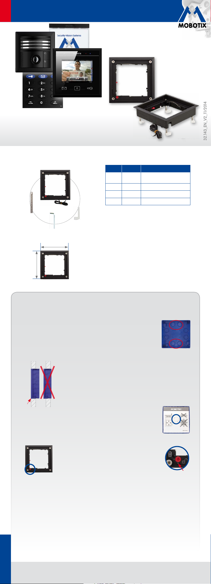
Delivered Parts
Order No.: MX-OPT-FlatMount-EXT-PW (white)
Security-Vision-Systems
32.143_EN_V2_11/2014
Item Number Part Name
1.4
1.3
124mm/4.88in
124mm/4.88in
1.1 1 FlatMount Frame with short
1.2 4 Clamping brackets, long
1.1
1.2
1.3 1 Allen wrench 2.5mm
1.4 1 FlatMount Frame ruler
Important Notes
• The FlatMount Frame is only to be used together
with the MxDisplay, the MOBOTIX door station
modules and the in-wall housings.
•
Make sure that you are installing this product on a
solid surface that provides for a sturdy installation
of the fixing elements used.
•
Make sure that the power supply is disconnected
before you insert or detach the modules.
•
This product must not be used in locations exposed
to the dangers of explosion.
clamping brackets
Installing the FlatMount Frame
Installation with In-Wall Housing
1. Lead Cable into the Housing
The housing has several cable inlets. Pierce through the required inlet with,
for example, a screwdriver. Make sure that you pierce through the inlet that is
closest to the required cable connection, i.e., use the upper inlet for a two-wire
cable and the lower for an installation cable.
2. Insert Housing
Prepare the installation opening for the in-wall housing (Wx Hx D): 112 x x
60 mm. You can use the reverted housing as a template to mark the opening.
Lead the cable into the housing. Make sure that the cable is long enough (about
40cm/16in), so that the wires can be connected easily to the FlatMount Frame.
Excess cable can be stored in the housing by winding it up in a spiral. Insert the
housing. Connect the in-wall housing in such a way with the underground that
the front edge of the housing lines up precisely with the housing surface.
Set the protective cardboard cover (included with the delivered
parts) into the housing before pushing it into the wall cavity. This prevents cement
from entering the interior of the housing. After you have installed the housing into
the wall, you can easily remove the carton by pushing through the pre-cut opening
and pulling it out.
3. Attach FlatMount Frame
The FlatMount Frame has an electromagnetic theft protection,
which prevents extracting the module. When attaching the frame,
make sure that the arrow on the red knob (theft protection) points
at the “open lock” icon and that the frame is positioned in such a
way that the red knob is on the bottom left corner of the frame.
Caution: In situations, in which a theft protection is not necessary, e.g., indoor installations,
do not activate the theft protection (the red knob remains in the “open lock” position).
!
Position the clamping brackets at the ends of the screws in such a way that the screws are easily led
past the notches of the housing when you attach the FlatMount Frame. After attaching the frame,
tighten the screws and make sure that you do not overtighten them. By tightening the screws, the
clamping brackets automatically engage into the notches of the housing.
If you twist the knob by mistake, you have to be able to attach a battery (9V DC).
Otherwise, the frame cannot be released!
MOBOTIX AG • D-67722 Langmeil • Phone: +49 6302 9816-103 • Fax: +49 6302 9816-190 • sales@mobotix.com
Page 2
EN
www.mobotix.com
112mm/4.41in
22mm/0.87in
2.24in
FlatMount Frame: Quick Install
Security-Vision-Systems
In-wall Installation in Cavities (without In-Wall Housing)
Installations in cavity walls without in-wall housings are possible in
materials that are 3 to 25mm/0.18 to 1in thick. For this installation type,
you need to replace the short clamping brackets that are attached to
the FlatMount Frame by the long clamping brackets included with the delivered parts (item 1.2). These
clamping brackets have to be shortened according to the thickness of the material.
1. Replace Clamping Brackets
Prepare the opening for the FlatMount Frame (W x H: 107x 107 mm). Measure the thickness of the
material. Cut the long clamping brackets that are included with the FlatMount Frame to the correct
length according to the thickness of the material. Replace the short clamping brackets that are
attached to the FlatMount Frame by the ones you just shortened.
To facilitate the installation, there are notches for the clamping brackets on three
corners of the FlatMount Frame. After you have attached the long clamping brackets
to the frame, turn three of the clamping brackets so that they fit into the notches.
Turn the fourth clamping bracket (on the corner without notch) downwards.
2. Insert FlatMount Frame
Insert the FlatMount Frame into the opening. Make sure that the
red knob is on the lower left corner and that the arrow on the red
knob points at the “open lock” icon. Insert the lower left edge of
the frame first, then follow with the lower right edge. After that,
slightly pull the lower part of the frame back out. This causes the
upper part of the frame to “fall” into the opening.
Caution: In situations, in which a theft protection is not necessary, e.g., indoor installations,
do not activate the theft protection (the red knob remains in the “open lock” position). If you
twist the knob by mistake, you have to be able to attach a battery (9V DC). Otherwise, the
!
frame cannot be released!
3. Tighten Screws
Tighten the screws and make sure that you do not overtighten them. The endings of the clamping
brackets hold the FlatMount Frame to the surface.
Mounting Several FlatMount Frame Units
You can mount several FlatMount Frames next to each other (vertically and horizontally). The delivered
parts of the housing include a connector block, which you can use to combine two housings.
1. Lead Cable into the Housing
See
«Lead Cable into the Housing»
make sure that you pierce the inlet that is closest to the required cable connection. The connecting
piece also has a cable inlet. Therefore, you can lead the cable connections of the second housing
through the first housing.
2. Insert Housing
See
«Insert Housing»
for the installation opening depends on the number
of FlatMount Frame units and the required connector
blocks:
(Width of all housings + width of connector blocks)
x 112 x 60 mm.
on the front. The measurement
Set the protective cardboard cover
(included with the delivered parts)
into the housing before pushing it
into the wall cavity. This prevents cement from entering the interior of the housing.
After you have installed the housing into the wall, you can easily remove the carton
by pushing through the pre-cut opening and pulling it out.
on the front. Since several cable inlets are possible here as well,
112mm/4.41in
57mm/
134mm/5.28in
112mm/4.41in
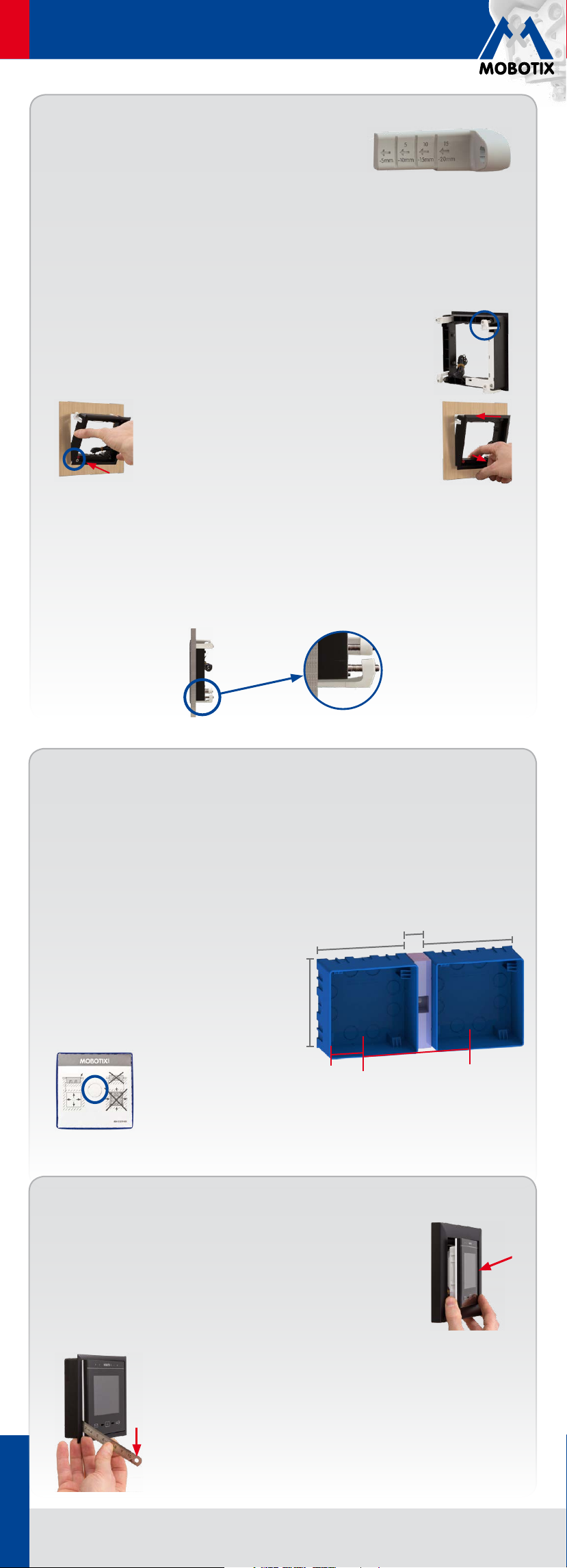
Inserting and Detaching Modules
Insert the Module (Using MxDisplay as an Example)
Make sure that the seal has been positioned properly on the back of the MxDisplay
and the protective foil has been removed. Insert the MxDisplay into the frame with
its right side first (this applies for both the single frame and the FlatMount Frame).
Then push the MxDisplay on the left side into the frame until it clicks into place.
Detach the Module (Using MxDisplay as an Example)
Insert the ruler (included with the FlatMount Frame) into the slit on the lower left
in such a way that the upper part of the ruler is on the same level as the lower
part of the MxDisplay image area. Push the outer end of the ruler downwards
MOBOTIX AG • D-67722 Langmeil • Phone: +49 6302 9816-103 • Fax: +49 6302 9816-190 • sales@mobotix.com
(see adjacent fig.). The MxDisplay is released on the left side, so you can pull it
from the frame.
Copyright © MOBOTIX AG 2014 • Made in Germany • Technical information subject to change without notice.
 Loading...