

Page 1
Standard Delivery
Uplink A B C D
48 V DC IN
MxSwitch
MxSwitch
• MxSwitch top-hat rail module with ip-top lid
Quick Install
MxSwitch
MxSwitch
5-port network switch for top-hat rail installation, for combined network connectivity and PoE+ power supply of up to
four MOBOTIX door stations, cameras or other PoE+ devices
More information:
www.mobotix.com > Products > Home Automation > MxSwitch
MX-SWITCH
32.797-001_EN_12/2016
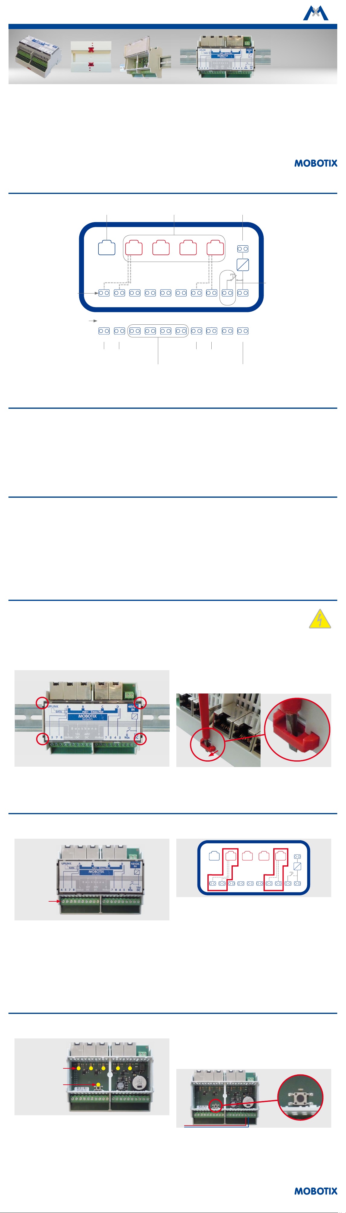
Connectors – Overview
Terminals
Network port
(e.g., router, computer)
Uplink A B C D
4 PoE+ ports (@ max. 25.5 W,
total load max. 75 W)
MxSwitch
1 2 3 4 5 6 7 8 9 10 11 12 13 14 15 16 17 18 19 20Terminal #
Spare wire pairs
(Port A)
Reserved for future extensions
(“Backbone”)
(ext. power supply 48 V DC, min. 2 A)
Power supply
48 V DC IN
Push-button switch
and terminals for
the protection
12 V DC90s4 57 87 84 5
12 V DC90s4 57 87 84 5
Spare wire pairs
(Port D)
Door opener
(max. 1 A)
Special Product Features
• Simple installation – just click onto top-hat rail.
• 4 PoE+-powered network ports (max. 25.5 W per port, max. 75 W
total load on all PoE+ ports combined)
• 1 network port for connecting LAN or computer (“Uplink”).
• Integrated power supply for door opener with 12 V DC, 1 A (e.g.,
switched by BellRFID or KeypadRFID).
Safety Warnings
•
The MOBOTIX MxSwitch is only to be used in switch boxes and must
be installed on top-hat rails (also “cap rail” or “DIN rail”).
• This product must not be used in locations exposed to the dangers
of explosion.
• Only use an external power supply with 48 V DC and min. 2 A.
•
Make sure to respect the operating temperature range of 0 to +40 °C
for the MxSwitch.
•
Electrical installation: Electrical systems and equipment may only
be installed, modied and maintained by a qualied electrician or
• Unused wire pairs 4/5 and 7/8 of network installation cables for
PoE ports A and D passed through to terminals.
• Push-button switch activates 12 V DC for 90 sec. on terminals
17/18 (to temporarily disable the protection of the frames of
door stations and MxDisplay units).
•
Integrated extensibility for additional top-hat rail modules (“Backbone”).
under the direction and supervision of a qualied electrician in
accordance with the applicable guidelines. Make sure to properly
set up all electrical connections.
•
Network security: MOBOTIX products include all of the necessary
conguration options for operation in Ethernet networks in compliance with data protection laws. The operator is responsible for the
data protection concept across the entire system. The basic settings
required to prevent misuse can be congured in the soware and
are password-protected. This prevents unauthorized parties from
accessing these settings.
Installing and Removing the MxSwitch
Caution – Danger of Life! Switch o all power to the switch box before working on the switch box and make sure that the
power lines do not carry any current!
1. Installing the Module
Place the module onto the top-hat rail at the desired location, then
gently press the module onto the rail at the indicated locations until
it clicks into place.
2. Removing the Module
Remove the network cable and any other cables or wires; isolate blank
wire ends, if required.
Push a suitable screwdriver into the red clip on one side of the module
(top or bottom), then gently pull the clip from the housing until it clicks
into the open locked position. Repeat the procedure on the clip on the
other side and remove the module.
Aer the clips have clicked into place, you can easily slide the module
on the rail until you have positioned it properly.
Connecting the MxSwitch and the Powered Devices
1. Notes on Connecting
Terminals
• Terminals 1 to 4: Spare wire pairs 4/5 and 7/8 on network port A.
• Terminals 5 to 12: Reserved for future extensions (“Backbone”).
•
Terminals 13 to 16: Spare wire pairs 7/8 and 4/5 on network port D.
• Terminals 17/18: Power supply for disabling the the protection
(see
«Deactivating the The Protection»
• Terminals 19/20: Power supply for door opener (e.g., switched
by BellRFID or KeypadRFID).
1 3 5 7 9 11 13 15 17 19
2 4 6 8 10 12 14 16 18 20
).
Aer removing the module, lightly press on the clips; they will jump
back into their original position.
2. Using the Spare Wire Pairs (Ports A and D)
48 V DC IN
Uplink A B C D
MxSwitch
12 V DC90s4 57 87 84 5
For these two ports, the wire pairs 4/5 and 7/8 have been looped through
to the terminals so they can be used for other purposes (see also section
«Example Scenarios»
Make sure to use a standard network installation cable since you need
to apply crimping plugs inside the switch box or use a patch eld to
connect the cable to the MxSwitch.
3. Using the Uplink Port
This port can be used to connect to another switch (and thus to the
network) or to a router. If this port is not used, you can connect a
computer to congure the network devices powered by the MxSwitch.
and the connection examples on page 2).
Notes on Using the MxSwitch
1. LED Signals
LEDs for net-
work ports
LED for the
protection
The MxSwitch has the following LEDs:
• 4 LEDs to indicate activity on the network port above each LED.
• 1 LED lights up aer pressing the push-button switch. The LED
stays on as long as the wires for deactivating the the protection is powered (see the following
Protection»
).
Section «Deactivating the The
2. Deactivating the The Protection
If the wires for deactivating the the protection of a MOBOTIX frame
for a door station or an MxDisplay have been connected to the terminals 17/18, you can press the push-button switch inside the module to
deactivate the the protection of the attached frames for at least 90 sec.
During this time, you can use the supplied key or ruler to open the frames
and remove the door station modules or the MxDisplay, respectively.
Caution:
without modules in the frame
protection actually works (please see the pertinent product documentation).
Aer connecting these wires,
to make sure that disabling the the
always run a functional test
Page 2
W
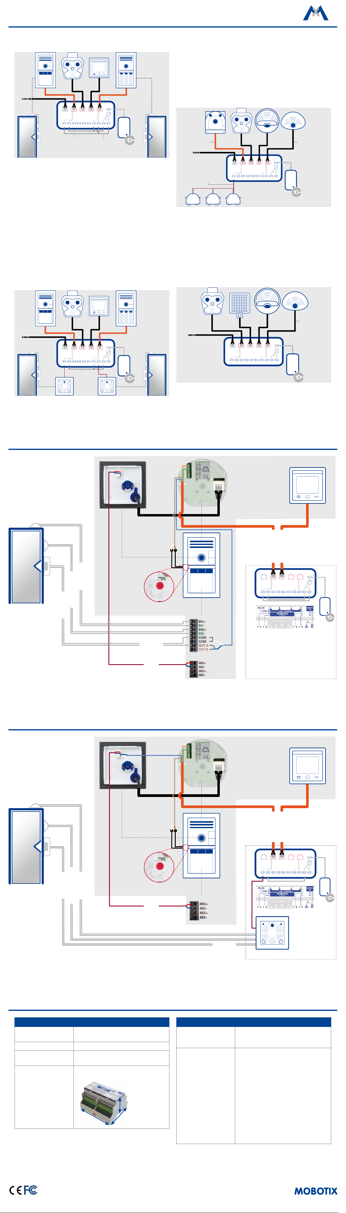
Example Scenarios
MX-DoorMaster
1. Two Door Stations, One M15, One MxDisplay
Uplink A B C D
MxSwitch
Bridge #1
• PoE power supply of all devices on ports A to D.
• Door stations attached to ports A and D.
• M15 and MxDisplay attached to ports B and C (PoE only).
• Bridge #1 at MxSwitch connects push-button key for the protection to wire pair 7/8 of the ports A and D.
• Bridge #2 at MxSwitch connects 12 V DC to wire pair 4/5 of the
ports A and D.
• Connect wire pair 7/8 of the network installation cable to the
protection of door station frames.
• Connect wire pair 4/5 of the network installation cable to signal
output of the BellRFID or KeypadRFID, respectively.
• Connect the signal outputs at the BellRFID and the KeypadRFID
to the door opener of the corresponding door.
48 V DC IN
12 V DC90s4 57 87 84 5
Bridge #2
=
• Connect each wire pair 4/5 of the network installation cable to
the MxBus connector of the corresponding door station.
• Connect each wire pair 4/5 of the ports A and D at the MxSwitch
with the corresponding MX-DoorMaster.
• Connect the door openers of the respective doors to the corresponding MX-DoorMaster.
3. Four Cameras
Network instal-
lation cable
48 V DC IN
12 V DC90s4 57 87 84 5
MxBus wires
GPS
Output
Uplink A B C D
MxSwitch
Input
• PoE power supply of all devices on ports A to D.
• Connect wire pair 4/5 of the network installation cable to the
MxBus connector of the camera at port A.
•
Connect wire pair 4/5 of port A at the MxSwitch to an MxBus module to which additional MxBus modules can be connected (such
as the MX-Output-Box and the MX-GPS-Box to the MX-Input-Box
in the example).
Patch cable
=
2.
Two Door Stations, One M15, One MxDisplay, Two MX-DoorMaster
Uplink A B C D
MxSwitch
48 V DC IN
12 V DC90s4 57 87 84 5
=
4. Three Cameras, One IR LED Light
Bridge #1
Dierences to Scenario 3:
Dierences to Scenario 1:
• Bridge #2 (see above) at the switch is omitted.
• The spare wire pairs of ports A and D are not used.
• Instead of a camera, the module supplies an IR LED light (25 W,
Connection Example in SmartAccessSet Without MX-DoorMaster
Uplink A B C D
MxSwitch
48 V DC IN
12 V DC90s4 57 87 84 5
with photoelectric switch) with PoE power.
Patch cable
=
Front Door
Door contact
Door lock contact
Door opener
(back)
T25-CamCore
The Protection
(in frame)
T25 Smart Access Set
12 V DC 1 A
MxBus
BellRFID connections (back)
Dr. Jones, MD
MX-OPT-IO2
(mounted in housing)
T25BellRFID
Network + PoE+
Network + PoE+
Uplink A B C D
MxSwitch
MxSwitch
MxDisplay+
48 V DC IN
12 V DC90s4 57 87 84 5
=
48 V DC 2 A
Power Supply
Switch Box
• Wire pair 4/5 connected to BellRFID signal output.
• Wire pair 7/8 connected to the protection.
Connection Example in SmartAccessSet With MX-DoorMaster
(back)
T25-CamCore
The Protection
(in frame)
Dr. Jones, MD
MX-OPT-IO2
(mounted in housing)
T25BellRFID
Network + PoE
Network + PoE
Uplink A B C D
MxSwitch
MxSwitch
MxDisplay+
48 V DC IN
12 V DC90s4 57 87 84 5
Front Door
Door opener
Door lock contact
Door contact
T25 Smart Access Set
BellRFID connections (back)
• Wire pair 4/5 connected to MxBus plug of the T25.
• Wire pair 7/8 connected to the protection.
Technical Specications
MxSwitch
Controls
Power Supply Ext. power supply 48 V DC, min. 2 A
Operating Conditions
Dimensions
Push-button switch inside puts 12 V DC
for 90 sec. on terminals 17/18
Indoor, operating temperature
0 to +40 °C
108 x 61 x 90 mm/
4.25 x 2.40 x 3.54 in (W x H x D)
H
D
MxBus
12 V DC 1 A
MxSwitch
Cross-sectional area
of wires at the terminals
Connections
=
Switch Box
0.2 to 2.5 mm²/24 to 14 AWG
• 2 terminals for ext. power supply
48 V DC
• 5 Ethernet connectors, 4 PoE+ (max.
combined total load 75 W), 1 uplink
(without PoE)
• Terminals 1 to 4 (Port A) and 13 to 16
(Port D) loop through wire pairs 4/5
and 7/8 of network cables
• 8 terminals for backbone pins (extension connector, reverse)
• 2 terminals for power supply 12 V DC,
1 A
• 2 terminals with 12 V DC, controlled by
push-button switch (see
«Controls»
)
48 V DC 2 A
Power Supply
MOBOTIX, the MX logo, MxControlCenter, MxEasy, MxPEG and MxActivitySensor are trademarks of MOBOTIX AG
registered in the European Union, the U.S.A., and other countries • Information subject to change without notice
• MOBOTIX does not assume any liability for technical or editorial errors or omissions contained herein • All rights
reserved • © MOBOTIX AG 2016
Declaration of Conformity: www.mobotix.com > Support > MxMedia Library > Certicates
Phone: +49 6302 9816-103
Fax: +49 6302 9816-190
www.mobotix.com
MOBOTIX AG
Kaiserstrasse
D-67722 Langmeil
 Loading...