

Page 1

EN
M24M: Camera Manual
The HiRes Video Company
More Camera For Less. Guaranteed!
The M24M series from MOBOTIX oers extremely compact, cost-eective and exceptionally powerful
allround cameras with the widest range of lenses, including panorama version. Fully equipped with
IP66-certified housing and long-term internal storage on a MicroSD card.
M24M Allround L22
60.176_EN_V3_01/2013
HiRes Video Innovations
The German company MOBOTIX AG is known as the leading pioneer in network camera technology and its
decentralized concept has made high-resolution video systems cost ecient.
MOBOTIX AG • D-67722 Langmeil • Tel: +49-6302-9816-103 • Fax: +49-6302-9816-190 • sales@mobotix.com
www.mobotix.com
M24M Allround L11
M24M Allround CS-Vario
Latest PDF file:
www.mobotix.com > Support > Manuals
Page 2

2/146
M24M Camera Manual: Camera Data
Enter your camera data here.
Camera Model:
Camera Name:
Factory IP Address:
Current IP Address:
DHCP:
Default User
Name: admin
Password: meinsm
Admin User Name:
Admin Password:
Note
MOBOTIX oers inexpensive seminars that include workshops and practical exercises:
Basic Seminar three days, Advanced Seminar two days.
For more information, please visit www.mobotix.com.
© MOBOTIX AG • Security-Vision-Systems • Made in Germany
www.mobotix.com • sales@mobotix.com
Page 3

Contents
CONTENTS
Foreword 6
The MOBOTIX Concept 8
MOBOTIX Hemispheric Technology 10
Superior Storage Solution 12
Added Security Value 14
Cost Benets and Technical Advantages 16
1 INTRODUCTION 18
1.1 M24M Overview 18
1.2 M24M With Hemispheric Special L11 Lens 26
1.3 M24M: HiRes Allround Camera With Widest Range Of Lenses 32
1.4 General MOBOTIX Camera Functions 34
1.5 Lens Options, Hardware And Software Features 40
2 INSTALLATION 44
2.1 Preparing The Installation 44
2.1.1 Flexible Installation Using VarioFlex Mount 44
2.1.2 Mounting To A Ceiling Or Wall 46
2.1.3 Mounting Tips For The M24M With L11 Lens (180° Fisheye) 47
2.1.4 Optional: Mounting To A Pole (With Accessories) 49
2.1.5 Network Connection And Power Supply, UPS 50
2.1.6 Preparing The Camera Connections, Wall Outlets 51
2.1.7 Wiring, Fire Prevention, Lightning And Surge Protection 52
3/146
2.2 M24M-IT/Secure: Delivered Parts, Components, Dimensions 54
2.2.1 Delivered Parts And Camera Components 54
2.2.2 Camera Housing And Connectors 55
2.2.3 Dimensions (mm) For Wall Installation 58
2.2.4 Dimensions (mm) For Ceiling Installation 58
2.2.5 Dimensions (mm) Of Wall Mount 59
2.2.6 Drilling Template (mm) Wall And Ceiling Mount 59
2.3 Available M24M Accessories - Overview 60
2.4 Mounting The Camera With Wall Mount 64
2.4.1 Mounting Instructions 64
2.4.2 VarioFlex Wall Mount 64
© MOBOTIX AG • Security-Vision-Systems • Made in Germany
www.mobotix.com • sales@mobotix.com
Page 4

4/146
M24M Camera Manual: Contents
2.4.3 Required Tools 66
2.4.4 Procedure 67
2.5 Mounting The Camera With Ceiling Mount 70
2.5.1 Mounting Instructions 70
2.5.2 VarioFlex Ceiling Mount 70
2.5.3 Required Tools 72
2.5.4 Procedure 73
2.6 Mounting The Camera With Pole Mount 76
2.6.1 Mounting Instructions 76
2.6.2 Pole Mount (MX-MH-SecureFlex-ESWS) 77
2.6.3 Procedure 79
2.7 Adjusting The Camera And Changing The Lens 82
2.7.1 Adjusting The Camera 82
2.7.2 Correcting The Image Horizon (For L11 Lens Only)
2.7.3 Changing The Lens 83
2.8 Replacing The MicroSD Card 84
2.8.1 Removing The MicroSD Card 84
2.8.2 Inserting The MicroSD Card 85
2.9 Network And Power Connection 86
2.9.1 Notes On Cable Lengths And Power Supply 86
2.9.2 PoE Variables 86
2.9.3 Power Supply Using A Switch 87
2.9.4 Power Supply When Connected Directly To A Computer 88
2.9.5 Power Supply (PoE IEEE 802.3af) Using Power Over Ethernet Products 88
2.9.6 Camera Startup Sequence 89
82
3 OPERATING THE CAMERA 90
3.1 Manual And Automatic Operation - Overview 90
3.1.1 Manually Using A Computer In The 10.x.x.x IP Address Range 91
3.1.2 Automatically Using MxControlCenter Or MxEasy 92
3.1.3 Automatically Using DHCP 93
3.2 First Images And The Most Important Settings 94
3.2.1 Manually Setting Up The Network Parameters In A Browser 94
3.2.2 First Images And The Most Important Settings In The Browser 96
3.2.3 First Images And Network Parameter Configuration In MxControlCenter 98
3.2.4 First Images And Network Parameter Configuration In MxEasy 103
3.2.5 Starting The Camera With An Automatic IP Address (DHCP) 108
3.2.6 Starting The Camera With The Factory IP Address 109
© MOBOTIX AG • Security-Vision-Systems • Made in Germany
www.mobotix.com • sales@mobotix.com
Page 5

Contents
3.3 Virtual PTZ 110
3.4 Correction Of Lens Distortion (L22 Only) 112
3.5 Special Hemispheric Conguration In The Browser (L11 Only) 114
3.6 MicroSD Card Recording 120
3.6.1 Introduction 120
3.6.2 Formatting The Card 122
3.6.3 Activate Recording 123
3.6.4 Accessing Camera Data 124
3.6.5 Deactivating The Card Memory 124
3.6.6 Using A MicroSD Card In A Dierent MOBOTIX Camera 125
3.6.7 Limitations On Warranty When Using Flash Storage Devices 125
3.7 Full Image Storage 126
3.8 Conguration In The Browser 128
3.8.1 Overview 128
3.8.2 General Browser Settings 128
3.8.3 Additional Configuration Options 131
3.9 Additional Notes 132
3.9.1 Protecting The Camera Against Condensation 132
3.9.2 Password For The Administration Menu 133
3.9.3 Permanently Deactivating The Microphone 134
3.9.4 Starting The Camera With The Factory IP Address 134
3.9.5 Reset The Camera To Factory Settings 134
3.9.6 Activate Event Control And Motion Detection 134
3.9.7 Deactivate Text And Logo Options 135
3.9.8 Deactivating The Daily Automatic Camera Reboot 135
3.9.9 Browser 135
3.9.10 Cleaning The Camera And Lens 136
3.9.11 Safety Warnings 136
3.9.12 Additional Information 137
5/146
Notes and Copyright Information
The enclosed Camera Software Manual contains detailed information on the camera
software. Download the latest version of this manual and the MxEasy and MxControlCenter
manuals as PDF files from www.mobotix.com (Support > Manuals). All rights reserved.
MOBOTIX, MxControlCenter, MxEasy, ExtIO and CamIO are internationally protected
trademarks of MOBOTIX AG. Microsoft, Windows and Windows Server are registered
trademarks of Microsoft Corporation. Apple, the Apple logo, Macintosh, OSX and Bonjour
are trademarks of Apple Inc. Linux is a trademark of Linus Torvalds. All other brandnames
mentioned herein may be trademarks or registered trademarks of the respective owners.
Copyright © 1999-2009 , Langmeil, Germany. Information subject to change without notice!
© MOBOTIX AG • Security-Vision-Systems • Made in Germany
www.mobotix.com • sales@mobotix.com
More information:
www.mobotix.com
Page 6
6/146
M24M Camera Manual: Foreword
FOREWORD
Dear MOBOTIX customer,
Congratulations on your decision to purchase an exceptionally versatile and innova-
tive premium network camera "Made in Germany." The M24M Allround Camera
features a 3.1 megapixel color sensor, an internal long-term memory with a
maximum capacity of 32GB and the latest technology platform from MOBOTIX.
This makes the M24M the first camera among the M models that can be fitted with
the MOBOTIX standard lenses (image angles from 15° to 90°), the hemispheric
L11 lens (image angle of 180°) for high-resolution panorama images and with com-
mercial CS-mount lenses.
This Camera Manual will give you an initial overview of the innovative MOBOTIX concept
that is at the core of this technology. This includes all the information you need to unpack
and install the camera (Chapter 2) and to view initial images on a PC (Chapter 3).
Please see the Software Camera Manual Part 2, included in the camera packaging, for
information on how to work with the many camera functions, such as event control or
image storage, for example.
If you would prefer to work with MxEasy or MxControlCenter instead of the browsercontrolled MOBOTIX camera software, you can download these programs for free including
a manual (PDF) from the MOBOTIX website:
www.mobotix.com/eng_US/Support/Software-Downloads
If you have any questions, our support and international sales sta are available at intl-
support@mobotix.com from Monday to Friday, 8 a.m. to 6 p.m. (German time).
Thank you for choosing MOBOTIX products and services, we trust you will be impressed
with the performance of your new M24M Allround Camera.
© MOBOTIX AG • Security-Vision-Systems • Made in Germany
www.mobotix.com • sales@mobotix.com
Page 7
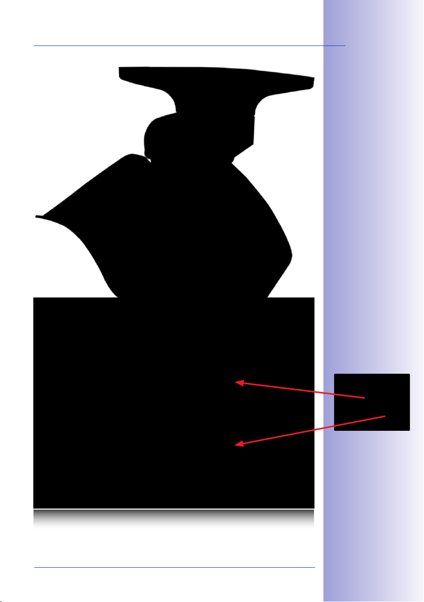
7/146
M24M - High-resolution
video surveillance
with optimal weather
protection (IP66)
MOBOTIX original
Double Panorama image
High-Resolution Double Panorama
© MOBOTIX AG • Security-Vision-Systems • Made in Germany
www.mobotix.com • sales@mobotix.com
Original full image
Page 8
8/146
M24M Camera Manual: The MOBOTIX Concept
THE MOBOTIX CONCEPT
HiRes Video Innovations
The German company MOBOTIX AG is known as the leading pioneer in network camera
technology since its founding in 1999, and its decentralized concept has made high-
resolution video systems cost-ecient. Whether in embassies, airports, railway stations,
ports, gas stations, hotels, or on highways - over one hundred thousand MOBOTIX
video systems have been in operation on every continent for years.
Technology Leader Of Network Cameras
In a short time, MOBOTIX has gained the second place in Europe and the fourth place
worldwide in terms of market share. MOBOTIX has been producing megapixel cameras
exclusively for years and, in this area, ranks as the global market leader in high-resolution
video systems with a market share of over 60%.
Why High-Resolution Systems?
The higher the resolution, the more accurate the detail in the image. With the old analog
technology, a live image has no more than 0.4 megapixels, and a recorded image generally 0.1 megapixels (CIF). Yet, one MOBOTIX camera with 3.1 megapixels records around
30 times more detail. This means that greater image areas, including 360° panoramas,
are possible, while still reducing the number of cameras, and thereby also the costs. For
example, four lanes of a gas station may be recorded with a single MOBOTIX camera,
instead of the four standard cameras normally necessary for such a task.
Disadvantages Of The Old Centralized Solution
Usually, cameras only supply images, while processing and recording take place later on a
central PC using video management software. This traditional centralized structure has many
limitations, since it requires highnetwork bandwidth and the PC processing power is insucient
when using several cameras. An HDTV MPEG-4 film already puts considerable strain on a PC,
how can it be expected to process dozens of high-resolution live
ized systems are therefore
less suitable and more
costly than high-resolution
systems due to the high
number of PCs required.
cameras?
Traditional central-
© MOBOTIX AG • Security-Vision-Systems • Made in Germany
www.mobotix.com • sales@mobotix.com
Page 9

The Decentralized MOBOTIX Concept
Unlike other systems, with the decentralized MOBOTIX concept a high-speed computer
and, if requested, digital memory (MicroSD/SD card) is built into every camera for longterm recording. The PC now serves purely for viewing, not for analysis or recording. As a
result, MOBOTIX cameras can record in response to an event, even without the PC being
switched on, and digitally store the videos with sound.
The Benets
MOBOTIX video solutions therefore require significantly:
• fewer cameras due to the more accurate detail of panoramic images with megapixel technology,
•
fewer PCs/DVRs, because around 40 cameras can store high-resolution videos with
sound eciently on a single PC, or no PC at all when recording in the camera using
digital memory (USB, MicroSD/SD card),
• lower network bandwidth, because everything is processed in the camera itself
and the high-resolution images therefore do not have to be constantly transported
for analysis.
Robust And Low-Maintenance
MOBOTIX cameras have no mechanical motors for lenses or for movement. Without any
moving parts, they are therefore so robust that maintenance is reduced to a minimum.
The unique temperature range from -30°C to +60°C (-22°F to +140°F) is achieved without
heating or a fan at approximately 4 watts. Since no PC hard drive is necessary for recording, there are no parts that wear out in the entire video system.
9/146
Software Included - For Life
There are no software or licensing costs with MOBOTIX because the software is always
supplied with the camera for an unlimited number of cameras and users. The software
package supplied with the camera also includes professional control room software similar
to those used in soccer stadiums, for example. Updates are supplied free of charge on
the website. The system price for a weatherproof camera, including lens, query software,
and day-to-day recording on the MicroSD/SD card, is under 1,000 euro.
One Camera For Four Gas Station Lanes - Long-Term Recording Without Additional Devices
© MOBOTIX AG • Security-Vision-Systems • Made in Germany
www.mobotix.com • sales@mobotix.com
Page 10
10/146
M24M with special
L11 lens and hemispheric technology
Original MOBOTIX
image; Wall-mounted at a
height of 2.3 m in a bank
M24M Camera Manual: MOBOTIX Hemispheric Technology
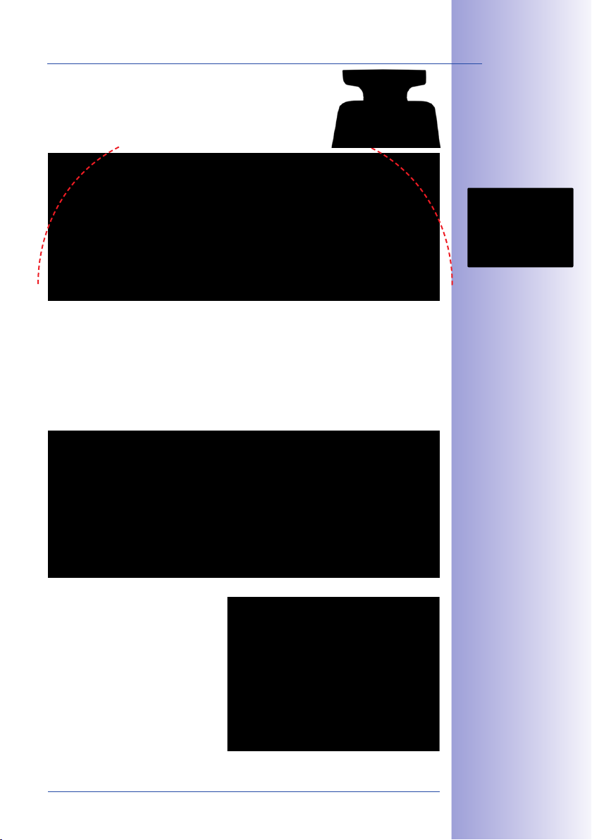
MOBOTIX HEMISPHERIC TECHNOLOGY (M24M-SEC-D11)
Perfect Room Overview
An entire room can be eectively monitored with innovative MOBOTIX Hemispheric Technology.
For instance, one single hemispheric camera replaces the time-consuming and expen-
sive installation of several standard cameras. The first of its kind in the world, this
camera is evidence of the MOBOTIX commitment to innovation as the global leader
in megapixel video security systems.
High-Resolution 180° Panorama
When several cameras are monitoring a single room, it is dicult to understand the
room layout in its single view. This makes it hard to comprehend the overall setting. The
new panorama function of the M24M delivers a widescreen image of a high-resolution
180° allround view. High image quality is achieved through the use of a 3.1 megapixel
sensor and the new hemispheric lens.
vPTZ control, also
using a USB joystick
High-Resolution 180° Panorama
Virtual PTZ (vPTZ) - Without Motor
The M24M also zooms in on detail. The
image of the Hemispheric camera can be
continuously enlarged and any image section
examined using a joystick, for example.
Thus you have a mechanical PTZ-camera
without maintenance or wear and tear.
While zooming into a section in the live
image, a full image can be stored in the
recording for later analysis. No PTZ-camera
in the world that operates with a motor
can do that!
© MOBOTIX AG • Security-Vision-Systems • Made in Germany
vPTZ
www.mobotix.com • sales@mobotix.com
Page 11

One Camera, More Views
The surround function of the M24M (ceiling mounted) immediately replaces four conventional cameras and shows four dierent directions simultaneously in quad view on a
monitor. Virtual PTZ is available for each of the four views. Together with the 180° panorama
the M24M can deliver two more views simultaneously, making it possible to see the
overview and to focus on two scenes at the same time (Display Mode “Panorama Focus“).
Panorama Focus: One Camera, Three Views
High-Resolution 180° Panorama
Virtual PTZ 1 Virtual PTZ 2
Highly User-Friendly
The full image from a hemispheric lens (Fisheye) is dicult to analyze. MOBOTIX solves this
problem by perfectly straightening the uneven lines in the live image using the camera
software. Since the image distortion correction of the hemispheric view and the generating
of the panoramic view take place in the camera itself, no additional load is placed on the
viewer PC, unlike a “standard” camera. Thus, displaying a large number of panoramic
cameras simultaneously on a single PC is possible.
11/146
Panorama Focus: Original
MOBOTIX image
Highly Ecient Image Transferring
While other camera systems always transfer the full images via the network for further
analysis, a MOBOTIX camera sends only the relevant image sections. Therefore, a Q24M
panorama image needs only about 1/6 of the original data volume or bandwidth. This
means up to six times more MOBOTIX cameras can transfer images over a network
compared to “standard” cameras.
Internal DVR With 32GB
The M24M stores high-resolution video with sound directly on the integrated Flash memory
without using an external recording device or PC, therefore using no additional network
load. Old recordings can be overwritten automatically or deleted after a predefined period.
The storage capacity is sucient for around 400,000 panorama images or 33 hours of
film (32 GB MicroSD).
© MOBOTIX AG • Security-Vision-Systems • Made in Germany
www.mobotix.com • sales@mobotix.com
Page 12
12/146
M24M Camera Manual: Superior Storage Solution
SUPERIOR STORAGE SOLUTION
The Market Demands Better Image Quality
When it comes to future-proof video surveillance systems, it is not a matter of analog
or digital but whether it is high-resolution or not. It is important to note that only
HiRes video with decentralized network camera technology can be implemented
at a much lower cost than any other type of video surveillance system.
Central Storage As A Bottleneck
These days, video data is normally pre-processed and stored centrally on a PC or DVR
using video management software. Video and audio streams from all installed cameras
are directed to this central device. This system is comparable to a highway at rush hour:
the more cameras there are, the faster a data jam on the PC or DVR occurs. This means
that despite HiRes cameras, the data is generally not stored in high-resolution format.
NON-MOBOTIX System
Motion detection and prealarm buer are in the PC
(bottleneck)
Storage
Central PC is a bottleneck and a risk for the total system
MOBOTIX Stores HiRes Cost Eciently
MOBOTIX solves the PC storage bottleneck problem using a unique and yet amazingly
eective method - through the camera itself. High-resolution video with lip synchronized
sound is saved either remotely over the network or locally on flash memory devices (commercial SD or CF cards, USB memory).
© MOBOTIX AG • Security-Vision-Systems • Made in Germany
www.mobotix.com • sales@mobotix.com
Page 13
Flash memory is a sophisticated form of semiconductor memory without mechanical
moving parts and represents the storage medium of the future thanks to its reliability,
ease of use and low cost.
MOBOTIX System
Network
Software and storage integrated in MOBOTIX cameras
MOBOTIX Saves To Flash
• No PC/network is required for continuous operations and there is no network load
• USB flash media can be connected directly to the camera (instead of internal SD/
MicroSD/CF card); no network is necessary
• Greater reliability (no hard drive)
• Ring buer: Old images can be overwritten automatically or automatically deleted
after a specified period of time
MOBOTIX Stores Data Reliably
The MOBOTIX Flash file system (MxFFS) prevents unauthorized persons from reading or
transferring the internally stored data, even if the card is stolen.
13/146
MOBOTIX Only Saves What Is Necessary
The MOBOTIX system includes three important
additional options that allow more data to be
stored for a longer time:
•
Only the relevant image sections are stored
instead of the entire image (for example,
sky or ceiling is removed)
•
Video recording only begins when relevant
events occur (such as movement in the image)
• Temporarily increased frame rate during
continuous recording of events
By connecting external memory over the network
(NAS), the system can be expanded without limitations, even while it is running.
MOBOTIX Data Storage
• Inside the camera - one MicroSD card is
enough to record all day long, making central
data storage devices or PCs unnecessary
• In USB storage (connection via
USB cable) data storage without
mechanical moving parts or
work load (greater protection
against data theft)
• A le server (NAS)
can store around ten
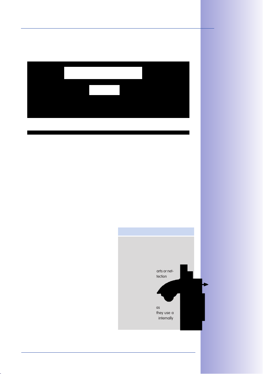
times more data from
MOBOTIX HiRes cameras
than usual because they use a
memoryorganization internally
© MOBOTIX AG • Security-Vision-Systems • Made in Germany
www.mobotix.com • sales@mobotix.com
net-
USB storage
Page 14
14/146
M24M Camera Manual: Added Security Value
ADDED SECURITY VALUE
Robust, Low-Maintenance Technology
The real added value of MOBOTIX products is reflected in
characteristics such as enhanced functionality, long life
and robustness. In general, MOBOTIX cameras have no
moving parts. This makes the cameras very resistant to
wear and tear, and reduces both maintenance costs and
power consumption.
Alarm Management And Forwarding
Integrated sensors enable MOBOTIX cameras
to recognize when an event has occurred. If
desired, the cameras will respond immediately
with an alarm sound and will establish
a direct video and audio connection to a
control room.
Absolute Data Security
The security barriers that are built into the camera are extremely secure. The camera
images are only accessible to authorized persons and are encrypted via SSL when they
are transferred over the network.
Notication Of Failure
MOBOTIX cameras will automatically report any impairment or failure. This ensures maximum reliability and readiness for use.
Floor plan and
camera view in
MxControlCenter
(free control center
software from
MOBOTIX)
Subsequent Searches
Events rarely confine themselves to just one spot. So even when you are looking at an
enlarged detail in live mode, it is always the full image that is recorded. And in this full
image, any section can always be enlarged later or whenever necessary.
© MOBOTIX AG • Security-Vision-Systems • Made in Germany
www.mobotix.com • sales@mobotix.com
Page 15

Sound Increases The Chance Of Detection
In the event of an alarm, MOBOTIX cameras can turn on their built-in microphones and
record lip-synchronous sound. They are therefore an even greater help in analyzing a
situation and easing clarification. In addition, the video system can be used for bidirectional
communication via a loudspeaker/microphone.
No Problems With Backlighting
MOBOTIX cameras are not adversely aected by the glare from direct sunlight. They
deliver meaningful, detailed images all the time because the camera software supports
easy programming of independent exposure windows to cope with specific situations.
This makes them ideal for rooms with large glass fronts.
Anti-Vandalism Dome Cameras
In critical environments or for outdoor use, it is often best to choose the optional
vandalism-protected MOBOTIX cameras. Their steel housing resists even the
hardest attacks, and the cameras will deliver a perfect image of the attackers.
15/146
Placing the exposure
window in the lower image
area (left image) delivers less optimum results
compared to moving
three individual exposure
windows up toward the
windows (right image)
© MOBOTIX AG • Security-Vision-Systems • Made in Germany
www.mobotix.com • sales@mobotix.com
D24M with Vandalism Set
Q24M with
Vandalism Set
Page 16
16/146
M24M Camera Manual: Cost Benets and Technical Advantages
THE MOST IMPORTANT COST BENEFITS
Increased resolution reduces amount of cameras needed
1536-line, high-resolution sensors give a better overview and allow monitoring
1
an entire room with just one camera from the corner
Reduced installation costs at any distance
Standard Ethernet connection enables the use of use of common network
2
components such as fiber, copper and wireless (WLAN)
Intelligent recording technology reduces required storage
Decentralized recording technology in the camera software puts less strain on PCs
3
and reduces the amount of storage PCs (DVRs) by 10 times
Event-controlled image rate minimizes storage costs
Event-driven, automatically adjusted recording frame rate based on event or
4
sensor action reduces amount of data and storage costs
No additional power and no heating required
Anti-fogging without heating allows usage of standard PoE technology to power
5
the system via network and saves costs of power cabling
Backup power requirement reduced by 8 times
Low power consumption, approx. 4 watts, enables year-round (no heating
6
required) PoE with one centralized UPS from installation room via network
Robust and practically maintenance free
Fiberglass-reinforced composite housing with built-in cable protection and no
7
mechanical moving parts (no auto iris) guarantees longevity
No software and no licence costs
Control and recording software is integrated in the camera and is free of charge;
8
new functions are available via free software downloads
Unlimited scalability and high return of investment
While in use, more cameras and storage can be added at any time; image
9
format, frame rate & recording parameters can be camera specific
Additional functions and other extras included
Audio support, lens, wall mount and weatherproof housing [-30°C... +60°C
10
(-22°F... +140°F)] are included; microphone & speaker available in certain models
© MOBOTIX AG • Security-Vision-Systems • Made in Germany
www.mobotix.com • sales@mobotix.com
Page 17
THE MOST IMPORTANT TECHNICAL ADVANTAGES
Progressive-scan instead of half-frame blur
Megapixel sensor and image processing inside camera with digital white
balance generates sharp and true color images at every scale
Sun and backlight compensation
CMOS-sensor without auto iris, digital contrast enhancement and configurable
exposure measurement zones guarantee optimal exposure control
Dual camera technology: 2-in-1
Two possible camera views with picture-in-picture technology or 180° panoramic
view; one Dual-Fixdome camera with 2.5 megapixel is enough
Long-term, high-performance Terabyte recording included
Event detection and ring buer recording by the camera itself allow
recording of 40 smooth video streams on a single PC (1200 VGA images/s)
Simultaneous recording, event search and live viewing
Live video for multiple users, recording and event search simultaneously
possible in seconds from anywhere in the world via network
Very low network load
Ecient MxPEG video codec, motion detection based recording and video
buering inside camera guarantee a very low network load
17/146
1
2
3
4
5
6
Bridging of recording during network failures
Internal camera ring buer bridges network failures and bandwidth
fluctuations of wireless links (WLAN/UMTS) for several minutes
Day & night maintenance free
Unique Day/Night camera technology without moving parts guarantees
extreme light sensitivity and ensures long-term reliability
Audio and SIP telephony
Lip-synchronized audio (live & recording); each camera is a video IP telephone
based on SIP standard with automatic alarm call and remote control
MxControlCenter included
Dual screen technology with building plans, free camera positioning,
event search, image processing, lens distortion correction and PTZ support
© MOBOTIX AG • Security-Vision-Systems • Made in Germany
www.mobotix.com • sales@mobotix.com
7
8
9
10
Page 18
18/146
M24M Camera Manual: INTRODUCTION
1 INTRODUCTION
1.1 M24M Overview
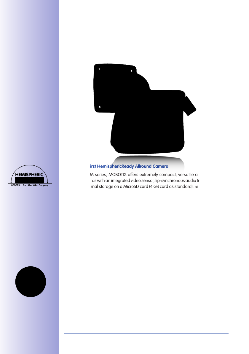
The World's First HemisphericReady Allround Camera
With the M24M series, MOBOTIX oers extremely compact, versatile and cost-eective
allround cameras with an integrated video sensor, lip-synchronous audio transmission and
long-term internal storage on a MicroSD card (4GB card as standard). Since the M24M is
equipped with the latest MOBOTIX technology platform, it is the first HempisphericReady
camera in the M series – capable of accepting the 11mm lens to give high-resolution
panoramic images.
MOBOTIX ExtIO
(Function Extension)
High Frame Rates Of Up To 30fps
Like all other MOBOTIX cameras, the M24M models can generate live video streams with
high frame rates and up to 3.1 megapixels image resolution (QXGA with 2048x1536pixels).
Up to 30fps are generated at a megapixel resolution of 1280x960 pixels. Even at 3.1
megapixels, the camera will still generate up to 20fps!
A Master Of Adaptability
The M24M models are accompanied by an extensive range of easily replaceable and
interchangeable lenses and a robust lens protector made of scratchproof special-purpose
plastic or glass. Application-optimized options for installation on walls, ceilings and poles, for
supplying power, or expanding the functions of the camera are also available. Furthermore,
MOBOTIX customers can take advantage of MxEasy or the professional control center
software MxControlCenter free of charge and with an unlimited user and camera license.
If required, an M24M camera can even be upgraded to function as a powerful intercom
system by adding the MOBOTIX ExtIO module.
© MOBOTIX AG • Security-Vision-Systems • Made in Germany
www.mobotix.com • sales@mobotix.com
Page 19

M24M Overview
Robust And Practically Maintenance Free
Thanks to their low power consumption of 3watts and the total absence of mechanical
moving parts, M24M cameras feature the highest operating temperature range (-30°C
to +60°C, or -22°F to 140°F). Since MOBOTIX cameras neither fog up nor require heating,
power can be supplied via the network cabling according to
the PoE standard IEEE802.3af. M24M IT and Secure models
are completely dust-proof and resistant to water jets (IP66). The
M24M Wall and Ceiling Mount supplied as standard makes
the camera ideally suited for outdoor use and for installation over flush-mounted sockets so that the cabling remains
perfectly concealed.
High-Resolution Sees More And Costs Less
One M24M camera equipped with a hemispheric or standard wide angle lens is usually
all that is required to monitor either an entire room or the four lanes of a gas station. The
high degree of image detail not only reduces the number of required cameras, but also
minimizes system costs by reducing the wiring complexity, emergency power requirements
and number of recording devices required. All M24M cameras feature direct recording to
integrated MicroSD cards or external USB drives and can therefore be used in standalone
operation with no additional network load.
One Camera For Four Gas Station Lanes – Long-Term Recording Without Additional Devices
19/146
VarioFlex wall mount
with concealed cabling
completely covers
ush-mounted sockets
Universal Application From The Vacation Home To The Airport
MOBOTIX M24M cameras are suitable for use in large-scale facilities, such as airports,
given their unlimited scalability and high performance. However, they are equally suitable
for use in small commercial or private buildings thanks to their integrated event, storage,
alarm and telephony functions. In addition, MOBOTIX recommends the M24M in combi-
nation with a hemispheric L11 lens as a superb, inspiring panorama webcam.
© MOBOTIX AG • Security-Vision-Systems • Made in Germany
www.mobotix.com • sales@mobotix.com
MOBOTIX original
180° Panorama
image (L11 lens)
Page 20

20/146
MOBOTIX original 90°
Super Wide Angle image
MOBOTIX original
180° Panorama
image (L11 lens)
M24M Camera Manual: INTRODUCTION
The Right Lens For Every Application
No MOBOTIX camera has ever had so many lens options! All five MOBOTIX standard
lenses, from the 15° Tele right through to the 90° Super Wide Angle, are oered with
the M24M.
Furthermore, the M24M is the first HemisphericReady camera from the M series and can
also be equipped with the hemispheric L11 lens (image angle of 180°).
The M24M-Sec-CSVario is an M24M model that is shipped with a CS mount and a
compact L24-L54 1/2" Vario lens. To protect the lens against the weather, this model
comes with a longer lens cover with an integrated glass pane which includes threads for
an external filter. This cover is suitable for lenses with a maximum diameter of 36 mm
and a maximum length of 43mm. Because of the image sensor's size of 1/2", CS and C
mount lenses for 1/2" sensors or larger that are designed for megapixel image sensors
can be used. In comparison with MOBOTIX fixed lenses, Vario lenses are less robust and
less reliable in the long run. For this reason, Vario lenses are typically used in applications
where recording conditions change frequently, for example, intermittent surveillance of
construction sites.
© MOBOTIX AG • Security-Vision-Systems • Made in Germany
www.mobotix.com • sales@mobotix.com
Page 21

M24M Overview
You can change all M24M lenses on site whenever necessary (except the hemispheric
L11 lens). Each lens is secured by a lock ring. The ordered lens is factory-aligned and
quality-tested in the camera, which makes on-site camera focusing unnecessary in most
cases. Each M24M is available for delivery with a lens of your choosing or no lens at all.
The image area captured by the camera varies depending on the selected lens (see
Section 1.5). With a Super Wide Angle lens (L22 with 90°), for example, almost an entire
room can be recorded from just one corner. A L135 Tele lens enables an M24M with a
high-resolution 3.1 megapixel sensor to clearly record a license plate number, for example, from a distance of approximately 75meters.
21/146
With an M24M equipped
with an L11 or L22
lens, the distorted
image can be corrected
by the software
MOBOTIX original
image (L135 Tele lens)
Or even the serial number of a bill from a distance of two meters.
© MOBOTIX AG • Security-Vision-Systems • Made in Germany
www.mobotix.com • sales@mobotix.com
MOBOTIX original
image (L135 Tele lens)
Page 22
22/146
Quick and easy
navigation with a
USB joystick
M24M Camera Manual: INTRODUCTION
Virtual PTZ (vPTZ) – Panning, Tilting, And Zooming With No Motor
The M24M can also zoom in on detail as well. This vPTZ function (virtual Pan, Tilt, Zoom)
is a standard feature in the integrated M24M camera software. The image from the
hemispheric camera can be enlarged using, for example, the mouse wheel, a joystick
or a software-controlled PTZ panel and you can "move" the view to any section
of the image. This provides the features of a mechanical PTZ camera without
the disadvantages of maintenance and wear.
vPTZvPTZ
© MOBOTIX AG • Security-Vision-Systems • Made in Germany
www.mobotix.com • sales@mobotix.com
Page 23
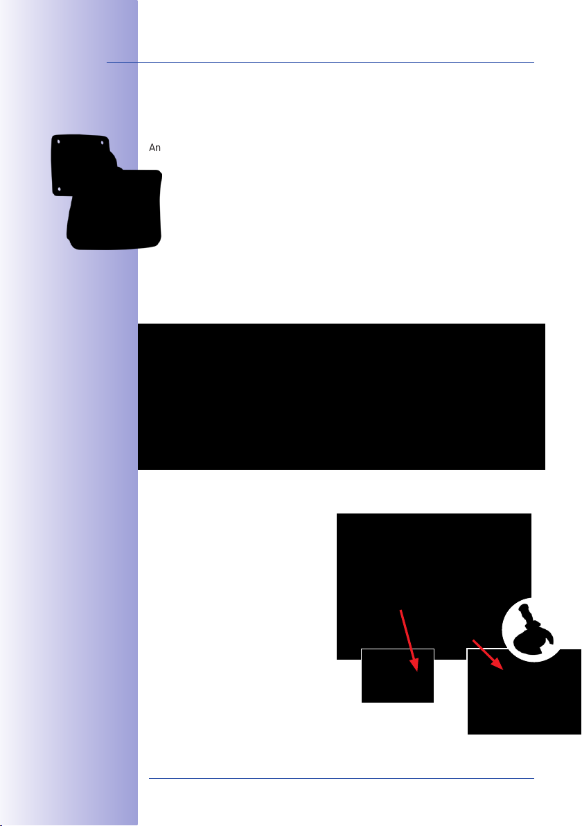
M24M Overview
Livebild Auswertung im VollbildGespeichertes Vollbild
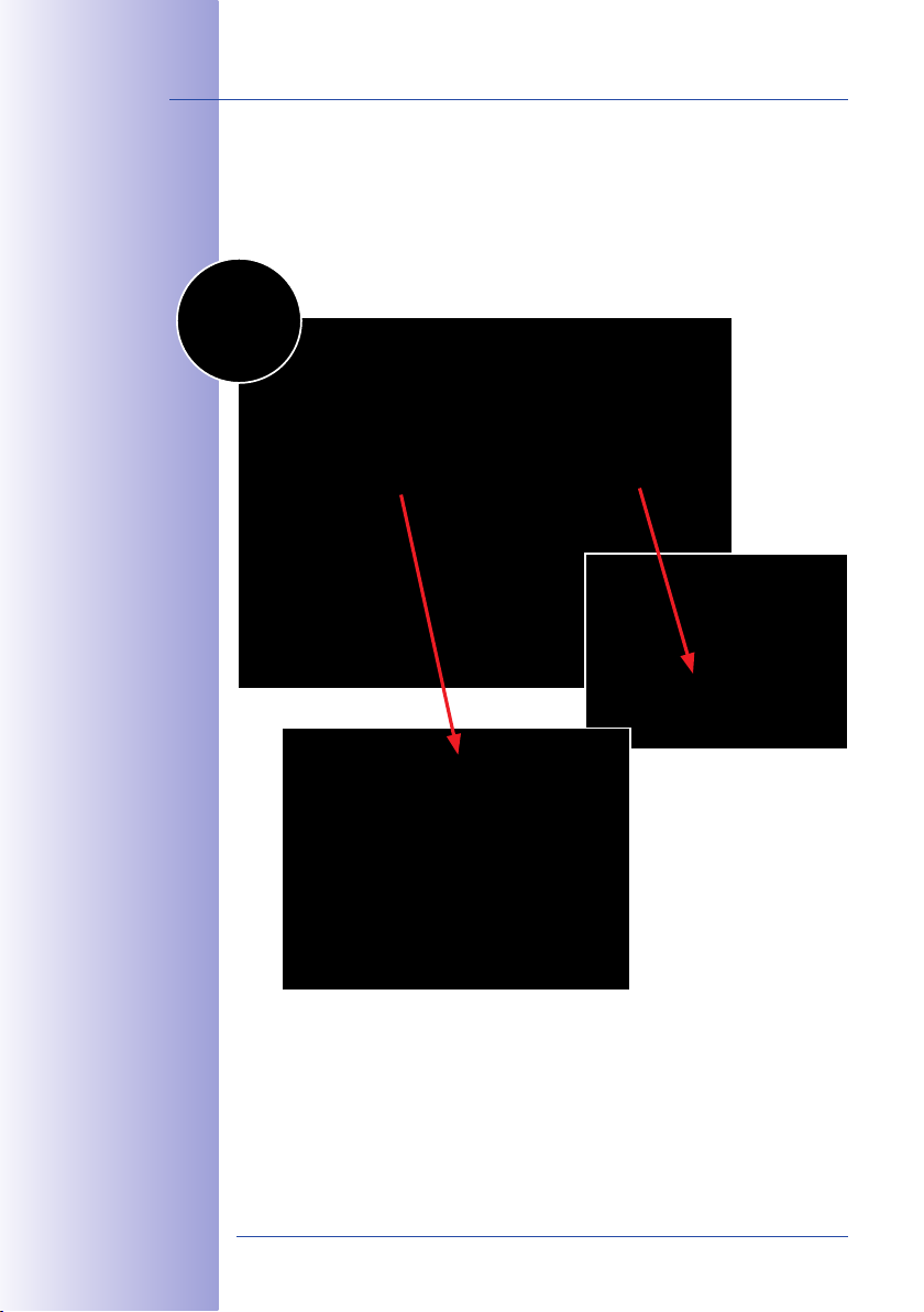
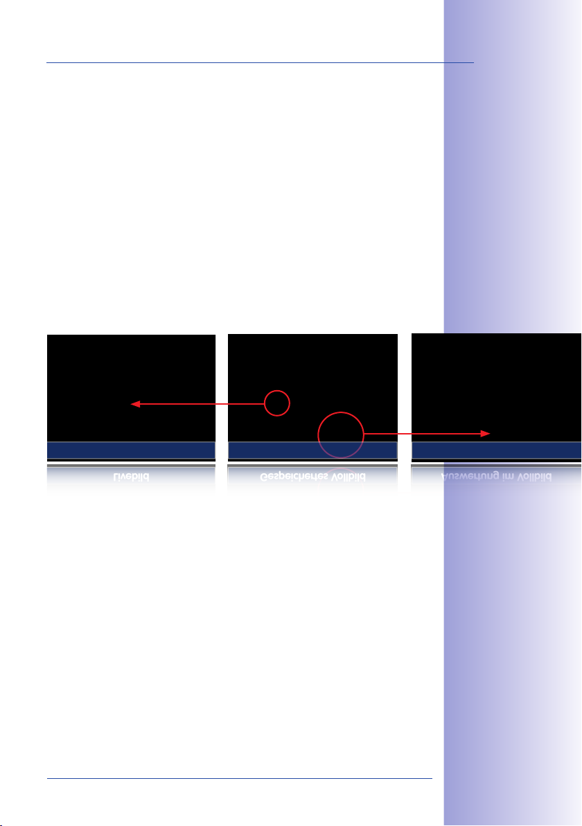
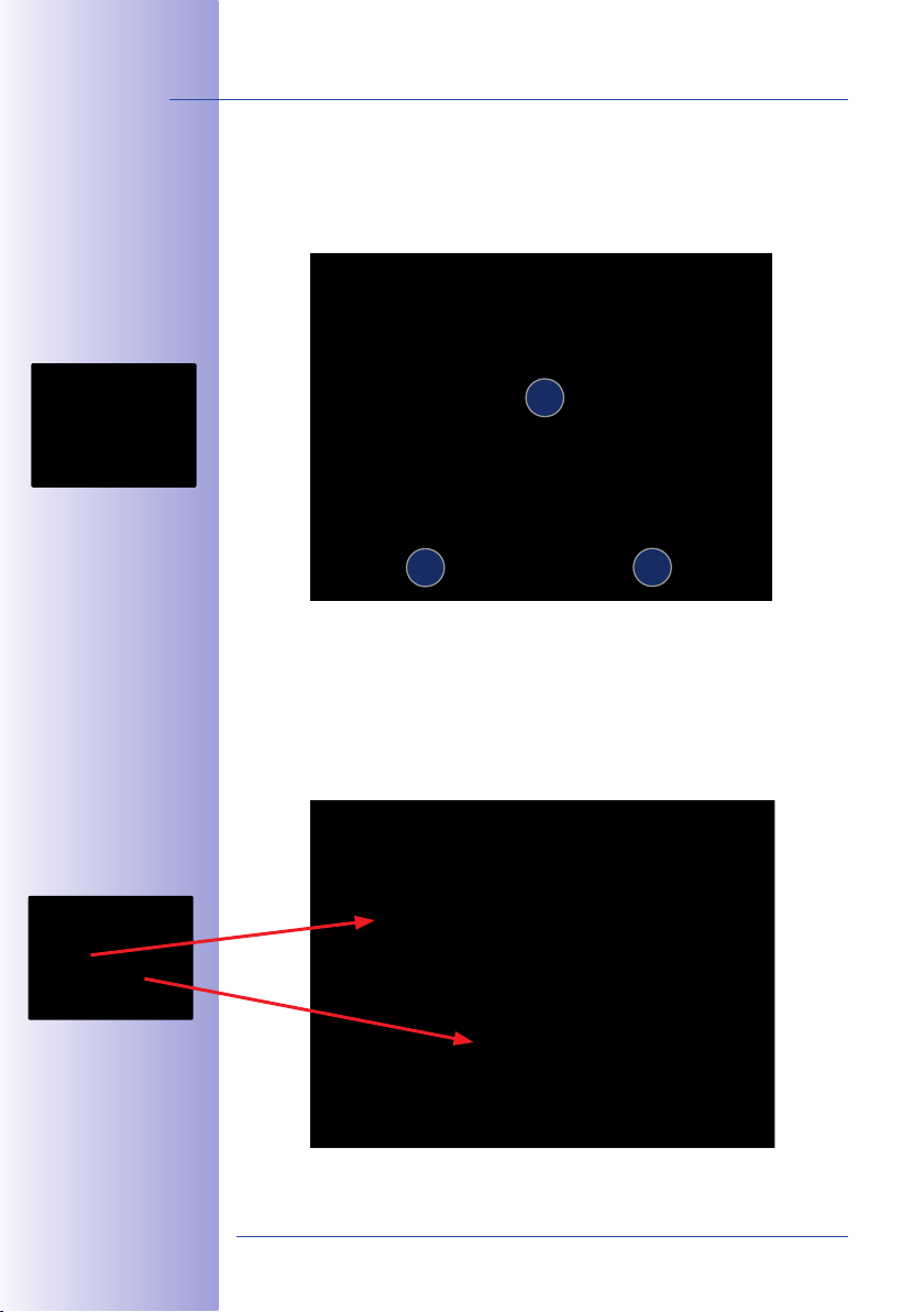
Simultaneous Zoomed Live Image And Full Image Recording
All conventional, motorized PTZ cameras only store the image that is currently viewed as
the live image (live image recording). This has one serious disadvantage as the record-
ing can only show what has happened in the "visible" portion of the image; the rest is
lost and cannot be examined later on. For this reason, MOBOTIX has added the new full
image recording feature to the M24M. This will not store the currently viewed image that
reflects the pan/tilt position and the zoom setting chosen by the user, but the full sensor
image – without vPTZ settings. When examining the recorded images at a later date, the
vPTZ features again come into play, as they allow the visible image to be zoomed and
use the pan/tilt features to examine every corner of the recorded full image.
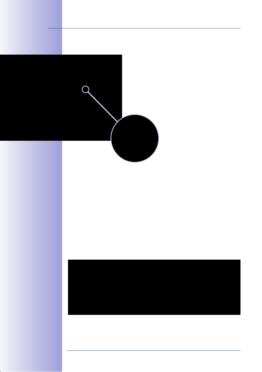
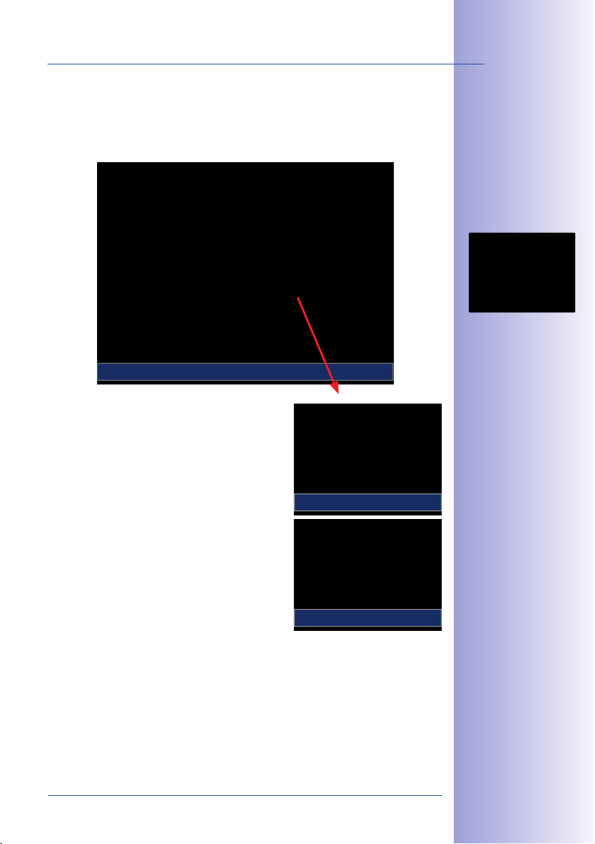
Example:The two people indicated by the red circles in the middle image would not have
been recorded by a regular PTZ camera. The full image recording of the M24M allows
you to determine, for example, the exact time at which these people entered the image
area recorded by the camera. A browser, MxControlCenter and MxEasy can be used to
examine the recorded sequences.
Live Image Analysis in Full ImageStored Full Image
23/146
Integrated vPTZ functions allow the complete
stored full image to be
analyzed at a later point
in time (in MxEasy and
MxControlCenter)
© MOBOTIX AG • Security-Vision-Systems • Made in Germany
www.mobotix.com • sales@mobotix.com
Page 24
24/146
M24M models with L11
and CS Vario lenses are
only available as Secure
models (see Section
1.5 for more details)
M24M Camera Manual: INTRODUCTION
Internal DVR
The M24M features direct recording to integrated MicroSD cards,
which makes the camera fully independent of any external storage media, even for longer periods of time. The camera internally
stores high-resolution video, without requiring an external record-
ing device or PC and therefore without overloading the network
whatsoever. Old recordings may be overwritten automatically or
automatically deleted after a specified period of time. A 32GB
MicroSD card, for example, allows the camera to store more than
half a million event images in VGA format (640x480). For security
reasons, the camera can even encrypt the stored data (available
in future software versions). Power failures are not an issue, as the
video and image sequences remain safely stored on the MicroSD card. Access to stored
video sequences is possible at any time from the camera user interface in the browser,
MxControlCenter or MxEasy. If you would like to archive sequences, you can export the
required data to a PC or USB stick for evidence purposes, for example.
Model Versions
The M24M is available in the Secure, IT or Basic models, which all come with dierent
features. The M24M is shipped with either a color or black and white image sensor (Day/
Night) and with an L22 Super Wide Angle lens (horizontal angle of 90°) as standard.
Furthermore, ve further factory lenses with image angles of 15°, 31°, 45°, 60° and
180° as well as a version with a CS Vario lens are available upon request. Every M24M
is provided with a pre-formatted and installed 4GB MicroSD card and a VarioFlex mount
for fast and easy installation.
Due to the extreme optical distortion of the M24M with the L11 sheye lens, special
requirements must be met with regard to the alignment of the hardware and software.
For this reason, interchangeable lenses cannot be used with this version. The camera's
lens is extensively and precisely fine-tuned in the factory and should not be adjusted.
L22–L135 L11 CS Vario
© MOBOTIX AG • Security-Vision-Systems • Made in Germany
www.mobotix.com • sales@mobotix.com
Page 25

M24M Overview
25/146
© MOBOTIX AG • Security-Vision-Systems • Made in Germany
www.mobotix.com • sales@mobotix.com
Page 26
26/146
M24M Camera Manual: INTRODUCTION
1.2 M24M With Hemispheric Special L11 Lens
Equipped with the 180° L11 lens, an entire room can be ideally monitored using just one
M24M, which replaces the time-consuming and expensive installation of several standard
cameras. The overview image provided by a single M24M, which may be personalized in
a number of ways according to specific user requirements, not only reduces the number of
required cameras, but also minimizes the system costs by reducing the wiring complexity,
emergency power requirements and number of recording devices required.
L11 Lens: High-Resolution 180° Panorama
When several cameras are monitoring a single room, it is dicult to understand the room
layout due to the dierent viewing directions of each individual camera. This makes it hard
to comprehend the overall setting. The new panorama function of the M24M with the
L11 lens delivers a widescreen, corrected image of a high-resolution 180° allround view.
High image quality is achieved through the use of a 3.1 megapixel color sensor and the
new hemispheric lens of the M24M.
With approximately 0.6 megapixels (1280x480 pixels), an M24M panorama image only
requires a fraction of the original data volume or bandwidth of a 3.1 megapixel full image
(1280x1536 pixels).
Corrected image after
panorama correction
Economical bandwidth
usage due to smaller,
camera-corrected
images (no loss of
image information)
Full image at 3.1 megapixel (2048 x 1536 pixels)
Panorama image at 0.6 megapixel (1280 x 480 pixels)
© MOBOTIX AG • Security-Vision-Systems • Made in Germany
www.mobotix.com • sales@mobotix.com
Page 27
M24M With Hemispheric Special L11 Lens
The factory default setting of an M24M with an L11 lens
is a high-resolution 180° panorama image, in which
parts of the protective cover are still visible in the upper
right and left corners of the image.
Optimizing The M24M Panorama Image
In order to hide the protective cover in the panorama image, all that is often required is
the "panorama correction" function, which has already been integrated into the camera
software (controlling the camera via a web browser). Tilted vertical lines (if the camera is
mounted at an angle) may be optically straightened to the image edges using this function (see Section 3.5). A welcome side eect of this is that the protective cover disappears
from the image.
27/146
Original full image
180° panorama image
after the panorama
correction function
has been applied
If this measure does not work in some
special cases (camera tilt of approximately 0°), the protective cover can be
removed from the image by zooming
and, if necessary, by using the purely
software-based downward panning
function. The displayed image section
or the panorama, as the case may be,
is reduced slightly but the image details
are enlarged as a result of zooming.
© MOBOTIX AG • Security-Vision-Systems • Made in Germany
www.mobotix.com • sales@mobotix.com
Section 3.5 provides
more details and information on how the panorama
and horizon correction
works (correct distortion in the image and
position horizontally)
Page 28
28/146
MOBOTIX original
Panorama Focus image
M24M Camera Manual: INTRODUCTION
L11 Lens: Panorama Focus – One Camera, Three Views
Maximum room overview while simultaneously viewing detail in a single image: the M24M
is capable of providing two more views simultaneously with the 180° panorama, allowing
you to focus on two scenes in parallel ("Panorama Focus" display mode).
32
1
Original full image
MOBOTIX original
Double Panorama image
Original full image
1
2
L11 Lens: Double Panorama For A Simultaneous View In Two Directions
The "Double Panorama" display mode provides a panorama image of both halves of the
area captured by the full image. Using the vPTZ functions, the panorama images can be
changed as desired. The example here shows an overview panorama of the entire room,
as well as the entrance, which would have otherwise no longer been visible in the
panorama – a superb overview for the user.
3
© MOBOTIX AG • Security-Vision-Systems • Made in Germany
www.mobotix.com • sales@mobotix.com
Page 29
M24M With Hemispheric Special L11 Lens
L11 Lens: Surround View (Quad View)
The M24M's "Surround" display mode replaces four cameras all at once and simultaneously delivers four dierent directions "at a glance." If the camera is installed in the ceiling
and is looking straight down, all four cardinal directions can be displayed, for example.
Surround View: Quad
Each of the four views features a software-controlled
pan/tilt/zoom function (virtual PTZ), allowing it to be
customized as necessary. In order to facilitate camera
operation, the M24M can store, in addition to the
preset standard views, a total of 256 user-dened
camera views using the vPTZ function, which can
easily be brought up using joystick keys or softbuttons.
Besides being able to manually bring up specific camera
views, the camera can also show them automatically.
It does so by moving through the standard views or by
showing the first 16 saved camera views (one af ter
the other like in a slide show).
vPTZ & Zoom
29/146
Original M24M image:
Each of the four
views can be indi-
vidually modied
Original full image
vPTZ & Zoom
© MOBOTIX AG • Security-Vision-Systems • Made in Germany
www.mobotix.com • sales@mobotix.com
Page 30

30/146
Original MOBOTIX
full image
Original MOBOTIX image
Corrected and
zoomed full image
M24M Camera Manual: INTRODUCTION
L11 Lens: Full Image And Normal View
In addition to Panorama, Double Panorama, Panorama Focus and Surround views, the
M24M image may be displayed on a monitor as the original fisheye version ("Full Image"
display mode) or as the camera-corrected image section ("Normal" display mode). Switching
to one of the other display modes described is possible at any time within seconds.
Original Fisheye Image: Full Image
Corrected Image Section: Normal
© MOBOTIX AG • Security-Vision-Systems • Made in Germany
www.mobotix.com • sales@mobotix.com
Page 31

M24M With Hemispheric Special L11 Lens
L11 Lens: Factory Settings Of The Standard Views For A Wall Installation
In order to fully exploit the potential of the M24M in the desired view, it may be necessary
to adjust the factory settings using the integrated vPTZ function. We have summarized
the factory default settings of a wall-mounted M24M with an L11 lens (with a downward
tilt of approx. 15°, 2.7m high) here in order to give you a good idea of what to expect
once the camera has been installed.
1
1
31/146
Full image (left)
and "Panorama" display mode (right)
1
2
1
2
1
2 3
1
2
1 2
21
3
4
3 4
© MOBOTIX AG • Security-Vision-Systems • Made in Germany
Full image (left) and
"Double Panorama"
display mode (right)
Full image (left) and
"Panorama Focus"
display mode (right)
3
Full image (left)
and "Surround" display mode (right)
www.mobotix.com • sales@mobotix.com
Page 32
32/146
M24M Camera Manual: INTRODUCTION
1.3 M24M: HiRes Allround Camera With Widest Range Of Lenses
The high-resolution Allround M24M camera is the more powerful successor to the M22M
and comes with a new microprocessor and a modified system platform. The result is more
than twice the processing power, which enables smooth video frame rates, even in the
high-resolution panorama display combined with the now available hemispheric L11 lens.
Double The Frame Rates Of The M22M
Even 3.1 megapixel camera images may be transferred at a rate of up to 20 frames per
second and megapixel images at up to 30 images per second.
Internal DVR With 4GB MircoSD Card
Every M24M is delivered with a high-quality, factory-installed 4GB MicroSD card (internal
DVR) as a standard feature – sucient for around 50,000 panorama images or ten hours
of HiRes continuous recording including audio (4 fps).
New, Waterproof Connections To The Camera
The network cable, the Mini USB cable and the MxBus for IO extensions are easily connected using waterproof connectors with bayonet catch in the back of the camera. The
standard weatherproof housing complies with the strict IP66 standard.
New VarioFlex Wall And Ceiling Mount
Simple and flexible installation using the extremely robust VarioFlex Mount (supplied as
standard) – including concealed cabling and an extra wide positional range for even
more installation options.
Adjustable PoE Classes, 1 To 3
The PoE class of the camera may be raised or lowered from the default value of 2 to 1 or
3 from the camera software in order to precisely adjust the functionality of the camera,
its accessories and the PoE switch.
Only 3 Watt Power Consumption
Despite the use of a more powerful processor, the power consumption of the M24M is
maintained at an extremely low level of only 3watts.
New Audio Functionalities
Microphone and speakers are integrated and, thanks to the new HiFi audio component,
the audio quality is once again improved and echoes during hands-free operation can
now be eliminated. If data protection requires it, microphone and audio recording can
be irreversibly switched o by securing the hardware.
© MOBOTIX AG • Security-Vision-Systems • Made in Germany
www.mobotix.com • sales@mobotix.com
Page 33

M24M: HiRes Allround Camera With Widest Range Of Lenses
33/146
© MOBOTIX AG • Security-Vision-Systems • Made in Germany
www.mobotix.com • sales@mobotix.com
Page 34

34/146
M24M Camera Manual: INTRODUCTION
1.4 General MOBOTIX Camera Functions
Like all MOBOTIX cameras, the M24M line has a variety of software functions: from motion
detection and long-term storage right through to alarm notification via video IP telephony.
Unlike in camera systems from other manufacturers, it is not necessary to buy and install
additional software on the computer. It is possible to use a web browser, however, you
can also download the free MxControlCenter or MxEasy from the MOBOTIX website, which
allow quick displaying of multiple cameras on one monitor, alarm switching with audio
or an easy event search.
Camera vPTZ functions
can be controlled with
a mouse or joystick
Using a joystick: Internet
Explorer with activated
MxPEG ActiveX plugin, MxControlCenter
or MxEasy required
MxControlCenter and
MxEasy can be downloaded free of charge
at www.mobotix.com
vPTZ: Virtual Pan/Tilt/Zoom Features
While MxControlCenter has been providing virtual PTZ features for some time now, these
features are now available directly in the MOBOTIX camera. This means that you can
continuously zoom into or out of the live image using either the mouse wheel or a joystick.
When storing images or video sequences, you can choose to store either the visible image
area of the live image or the full sensor image (full image storage). This also allows you
to examine parts of an image or video that had not been visible in the live image section
on display at the time of the recording.
Automatic Image Correction (Only With L22 Or L11 Lenses)
Another problem familiar from the field of photography are the distortions that result from
using wide angle lenses. Straight lines near the image borders are curved. The integrated
distortion correction features of the camera (and of MxControlCenter) allow the curve of
various lenses to be corrected using software functions.
Live Video With Up To 30 fps, Including Audio
MOBOTIX cameras deliver smooth live video with lip-synchronous audio, yet they keep
network load to a minimum. Some analog systems may also be able to deliver this, but the
recording quality is so much higher with MOBOTIX since the cameras eciently store the
high, live image resolution and frame rate without compromising image quality. MOBOTIX
technology thus provides for continuous recording of simultaneous video from 30 cameras
at 30frames per second each, including audio, all on one standard PC.
Very Low Network Load
MOBOTIX's patent-pending streaming format MxPEG enables fast live video with audio
at extremely low network load (1 to 2Mbps). Since the MOBOTIX camera itself detects
movements in the image (and not the computer), video sequences are only transmitted
when they are being stored externally.
© MOBOTIX AG • Security-Vision-Systems • Made in Germany
www.mobotix.com • sales@mobotix.com
Page 35

General MOBOTIX Camera Functions
Voice Over IP
Moreover, MxPEG provides for lip-synchronous live audio and two-way communication
between the camera and a computer. Room surveillance is possible using a browser
(Internet Explorer), MxControlCenter, or MxEasy. Customized alarm notification on your
mobile phone or via Internet telephony is just as easy as event-controlled voice messages
directly from the camera.
Internet Telephony (SIP) And Video SIP
Video SIP allows audio/video connections to
be established to the camera using Windows
Messenger or similar applications (for example,
CounterPath X-Lite/Eyebeam). This feature also
allows the camera to be remote controlled
using the phone keys and the camera itself
can place phone calls in case of alarms.
Long-Term Storage On File Servers Included
MOBOTIX cameras have an integrated long-term storage system for Linux, Windows, and
Mac OS X computers. Every camera manages its own ring buer storage to a shared
folder. Thanks to this decentralized approach, 30 live cameras can store images of up to
30 frames per second each, including audio, on a single computer.
Internal DVR: Storage On MicroSD And CF Cards
MOBOTIX cameras support direct storage on an internal MicroSD/SD/CF card (Basic models
excluded). By using this integrated flash card DVR, the camera is able to oer the following
additional applications:
35/146
• Standalone use of the camera without a file server by recording to the MicroSD card
• High-security application with recording on a file server or NAS/SAN in which the
SD card serves as storage buer. It can thus bridge longer network or file server
failures without losing any video sequences (supported in a future software version).
• Event downloads from the MicroSD card for evaluation of the recorded sequences
on a computer
Internal DVR External USB Storage Comments on USB Storage
M12 optional optional Adapter cable required
D12 optional optional Adapter cable required
V12 optional - -
M24M
D24M
Q24M
included (upon delivery)
included (upon delivery)
included (upon delivery)
optional Device can be connected directly
optional Adapter cable required
optional Adapter cable required
© MOBOTIX AG • Security-Vision-Systems • Made in Germany
www.mobotix.com • sales@mobotix.com
Internal DVR is either
an option during order
placement (for example,
M12 R16) or upgradeable
later with an SD card
A 4 GB MicroSD card is
included with the M24M
Page 36

36/146
No heating required
– PoE is no problem,
even in winter
M24M Camera Manual: INTRODUCTION
Event And Time-Controlled
Just like triggering event-controlled recording upon detecting movements in the image,
the camera can also record when the volume detected by the microphone exceeds a
certain trigger value. Using scheduled daily recording, time tasks can start or stop video
recording, upload images to a website, or send e-mails with video/audio clips. Vacation
times and holidays can be programmed.
Remote Alerting
In case of an alarm, MOBOTIX cameras can automatically pop up windows or activate
other functions at a remote security control center. The cameras can use network/wi-fi,
GSM/GPRS/UMTS (3G), or Internet connections for this purpose.
Integrated Power Over Ethernet
Power is supplied as Power over Ethernet via the network cabling using the MOBOTIX NPA-
PoE-Set or from a PoE-compatible switch (both according to the IEEE 802.3af PoE standard).
Caution
Previous MOBOTIX network power accessories such as the NPA Set, Power Box,
and Power Rack (MX-NPA-Set, MX-NPR-4, and MX-NPR8/20) are not suitable for
use with the M24M.
No heating is necessary thanks to the well-insulated plastic housing and anti-fogging
properties. Due to their low power consumption (approximately 3 watts), MOBOTIX cameras, unlike those of other manufacturers, may be operated both indoors and outdoors
using a PoE power supply.
Logo generator for
displaying graphics
already integrated
in the live image
Logos, Animated Or Freestyle
The MOBOTIX camera logo generator allows time-scheduled banners and graphics (includ-
ing files loaded automatically from any URL) to be integrated into the current camera
images. MOBOTIX cameras are the only network IP cameras supporting animated and
transparent graphics.
© MOBOTIX AG • Security-Vision-Systems • Made in Germany
www.mobotix.com • sales@mobotix.com
Page 37

General MOBOTIX Camera Functions
MxControlCenter – Professional Video Management Free Of Charge
Instead of using a web browser, you can also download the free-of-charge MxControlCenter
from the MOBOTIX website (www.mobotix.com), which allows you to quickly display live
images with audio transmission from high-resolution MOBOTIX cameras. In addition,
MxControlCenter can process incoming alarms with lip-synchronous sound and allows
comfortable search and evaluation of alarm video clips. The integrated Layout Editor of
MxControlCenter allows you to quickly create floor plans by simply dragging/dropping the
cameras onto a background image. Load a floor plan as background image, drag and
drop the cameras; done!
37/146
Also manages several
hundred cameras all
on one standard PC
Free download at
www.mobotix.com
No license costs
Free updates
MxEasy – Intuitive Application For Windows, Apple And Linux
The new MOBOTIX MxEasy aims at easy operation of the most important camera functions
through its intuitive user interface, thus creating a new user experience when viewing and
controlling MOBOTIX cameras. The clear design allows up to 16 cameras to be managed,
and the application can show up to four cameras at the same time.
© MOBOTIX AG • Security-Vision-Systems • Made in Germany
www.mobotix.com • sales@mobotix.com
Suitable for up to 16
MOBOTIX cameras
Free download at
www.mobotix.com
No license costs
Free updates
Page 38

38/146
M24M Camera Manual: INTRODUCTION
All settings selected in MxEasy (for example, virtual camera position, zoom, brightness,
volume, microphone sensitivity, image storage, signal outputs) are usable immediately
and are stored instantly in the configuration of the corresponding camera. The calendar
function integrated in the Alarm Planner
provides access to innovative features for
scheduled settings of one or more cameras.
For the first time, this tool not only controls
video and audio recording based on certain
time and date information, but also allows
features like video motion detection, image
brightness, and the microphone to be
activated/deactivated based on a date
and time schedule.
MxEasy is available as a free-of-charge download for the Windows and Mac OS X operating
systems under www.mobotix.com. A Linux version will be available soon.
Diverse Installation Options
Not only can MOBOTIX cameras be used under almost all weather and temperature conditions,
they also oer suitable installation materials from a wide range of accessories for any
conceivable application scenario.
Additional Camera Functions (Software)
• True software scaling to easily generate smaller image formats for PDAs (such as
320x240, 160x120, etc.)
• Audio-video recording with three dierent recording modes: event recording with
audio, continuous recording with variable frame rate and audio as well as eventcontrolled snapshot recording of JPEG images
• Storage failure detection can monitor a file server (or a flash device) and can use
one or more of the defined messaging options for error notification
• Player of recorded images/video sequences with audio in the integrated video
management system
• Multiwatcher screen can display and monitor several cameras over the Internet,
with only one camera requiring access from the outside. This "proxy" camera uses
only very little bandwidth, making it an ideal solution for low-bandwidth connections
•
MultiView screen for displaying multiple cameras or events in one browser window
•
Event notification by e-mail, text messaging (using a service provider), voice notifica-
tion (Phone Call-Out), sounds, and by visual means (for example, red frame in live
image) using two separate messaging paths
• Object tracing for analyzing the paths of objects that are moving in the image
© MOBOTIX AG • Security-Vision-Systems • Made in Germany
www.mobotix.com • sales@mobotix.com
Page 39

General MOBOTIX Camera Functions
• Time Tables with handling of customized holidays and vacations. The time tables
are used to control the camera's arming, image recording messaging, logos, the
obscure image function as well as other features.
• Remote signaling for master/slave cameras, with the master camera controlling
the arming status of the slave cameras. This allows, for example, all slave cameras
to be armed using a key switch connected to the master camera.
• Transfer proles for comfortably controlling transmissions via FTP, e-mail, phone
calls and network messages
• Speakerphone* with speak, listen and intercom modes using the microphone and
speaker
• Phone Call-In* to remotely control the camera using a touchtone telephone
(retrieve camera information, establish an Internet connection, announce the retrieved
IP address, intercom feature, etc.)
• MxPEG video compression using MxControlCenter. The ActiveX plug-in for Internet
Explorer users brings all advantages of MxPEG to the browser-based user interface
(including the audio stream to and from the camera)
• Routing allows use of other network connections besides the standard route
• DynDNS client for accessing the camera via the Internet using a symbolic name
(for example, mymobotixcam.dyndns.org), despite the provider assigning a new
dynamic IP address every time the camera connects to the Internet
• Non-voidable backup system starts the cameras in the original operating state
if a software update fails, allowing the user to easily restart the update process
• Enhanced startup options for the camera (obtain IP address via DHCP, announce-
ment of IP address and other network data, reset to factory default settings)
• Notications upon errors or when rebooting provide a method for executing one
or more notifications (for example, blinking of the camera LEDs, audio message, FTP,
e-mail, phone call, network message)
• Extended security features protect the pages and features of the camera and
prohibit unauthorized access (IP-level access control, intrusion detection). They also
provide SSL-protected transmission of the video sequences and the data (using SSL
encryption and X.509 certificates).
39/146
* Telephony features
using VoIP connections
(Internet telephony)
Free Software Updates (www.mobotix.com)
MOBOTIX provides software updates free of charge at regular intervals that improve
and expand the camera’s functionalities. Chapter6,
provides more information on the process.
Manual
Software Update
, in the
Software
© MOBOTIX AG • Security-Vision-Systems • Made in Germany
www.mobotix.com • sales@mobotix.com
Free software
updates at
www.mobotix.com
Page 40

40/146
M24M Camera Manual: INTRODUCTION
1.5 Lens Options, Hardware And Software Features
MOBOTIX oers the M24M with lenses in three dierent classes of focal length. Since
MOBOTIX cameras are backlight-proof, none of these lenses requires a mechanical auto
iris, thus making the camera extremely robust and maintenance-free. MOBOTIX lenses
deliver good image quality even when using maximum digital zoom.
L11 Hemispheric 180°
L22 Super Wide Angle 90°
L32 Wide Angle 60°
L43 Wide Angle 45°
L65 Tele 31°
L135 Tele 15°
M24M With Standard Lenses And M14 Thread
A total of five dierent MOBOTIX lenses are oered:
•
L22 Super Wide Angle with 90° image angle (horizontal)
• L32 Wide Angle* with 60° image angle (horizontal)
• L43 Wide Angle with 45° image angle (horizontal)
• L65 Telephoto with 31° image angle (horizontal)
• L135 Telephoto with 15° image angle (horizontal)
The standard lenses can be exchanged at any time without having to dismantle the
camera. The camera is shipped either with a color day sensor or a light-sensitive black
and white sensor for low lighting conditions (day or night versions).
M24M With Hemispheric L11 Lens (Fisheye)
The hemispheric M24M model (M24M-Sec-D11) is only
shipped with one L11 fisheye lens with a horizontal image
angle of 180° and 3.1 megapixel color sensor. The lens
distortion that is specific to each lens is corrected in the live
image by the MOBOTIX camera software. Due to the special
outdoor-optimized design of the camera, the full sensor image
cannot be used with all available image display options (parts of the weatherproof hous-
ing may be visible in the image). With this model, it is not possible to switch to another
lens at a later stage.
M24M With CSVario Lens
The M24M-Sec-CSVario is shipped with a CS mount, a compact
L24-L54 1/2" Vario lens (image angle from 58° to 28°) and
an optional color or black and white sensor (day/night).
In addition, commercial CS and C mount lenses (C mount
lenses with adapter ring) with a diameter of up 36mm and
a length of up to 43mm that are designed for megapixel image sensors (1/2“ and larger)
can be used. Using other lenses will produce shadows at the image borders and will
reduce image sharpness.
CS-Vario 73° – 37°
© MOBOTIX AG • Security-Vision-Systems • Made in Germany
www.mobotix.com • sales@mobotix.com
Page 41

Lens Options, Hardware And Software Features
41/146
Lenses
Original
image
35mm
equivalent
Actual focal
length
Aperture
Horizontal
image angle
Vertical
image angle
Dist. 1 m
Image width
Image height
Dist. 5m
Image width
Image height
Dist. 10m
Image width
Image height
Dist. 20m
Image width
Image height
Dist. 50m
Image width
Image height
L11 L22 L32 L43 L65 L135 CS Vario
11mm 22mm 32mm 43mm 65mm 135mm
1.8mm 4mm 6mm 8mm 12mm 25mm
2.0 2.0 2.0 2.0 2.0 2.5 1.6–2.3
180° 90° 60° 45° 31° 15° 73°–37°
160° 67° 45° 34° 23° 11° 58°–28°
m m m m m m m
infinite 2.0 1.1 0.8 0.5 0.3 1.5–0.7
11 1.3 0.8 0.6 0.4 0.2 1.1–0.5
m m m m m m m
infinite 10.0 5.7 4.1 2.7 1.3 7.4–3.3
55 6.6 4.1 3.0 2.0 1.0 5.5–2.5
m
infinite 20.0 11.5 8.2 5.5 2.6 14.8–6.7
110 13.3 8.2 6.1 4.0 1.9 11.1–5
m m m m m m m
infinite 40.0 23.0 16.4 11.0 5.2
220 26.6 16.4 12.2 8.0 3.8 22.2–10
m m m m m m m
infinite 100.0 57.5 41.0 27.5 13.0 74–33.3
550 66.0 41.0 30.5 20.0 9.5 55–25
m m m m m m
24–54mm
4.5–10 mm
29.6–13.3
Notes
The specified focal lengths of MOBOTIX lenses do not reflect the actual focal length
of the lenses, but the focal length (Lxxmm) converted to 35mm camera format. For
example, the MOBOTIX L22 Super Wide Angle lens has an actual focal length of
4mm. This would be the equivalent of 22mm on a 35mm camera. It is therefore
referred to as an L22. Since the image sensors in digital cameras have dierent
sizes, converting the focal lengths to 35mm camera as a known format allows the
image formats and the fields of vision of the dierent lenses to be calculated and
compared more easily. Another benefit is that you can easily set a 35mm camera
(analog or digital) to the same focal length as the MOBOTIX lens (Lxx) to obtain the
same field of vision. This approach greatly facilitates lens selection.
© MOBOTIX AG • Security-Vision-Systems • Made in Germany
www.mobotix.com • sales@mobotix.com
Page 42

42/146
*Special Mini USB
adaptor cable available as an accessory
**A 4 GB MicroSD
card is shipped with
all M24M models
MicroSD cards of up to
32 GB may be used (SDHC)
M24M Camera Manual: INTRODUCTION
M24M-IT
MX-M24M-IT-D22
M24M-Sec
MX-M24M-Sec-D22
M24M-Sec-Night
MX-M24M-Sec-Night-N22
M24M-Sec-Hemispheric
M24M Hardware Features
Outdoor weatherproof IP66 IP66 IP66 IP66
Ethernet/Mini USB* X/X X/X X/X X/X
MicroSD slot X X X X
Mono (M)/Dual (D) M M M M
Image sensor Color Color B/W Color
Lens L22 L22 L22 L11
Resolution VGA 3 MEGA 1 MEGA 3 MEGA
Resolution horizontal x vertical 640x480
Max. frame rate CIF/VGA/MEGA/3MEGA (fps)
Sensitivity at 1/60 second (lux) 1 1 0.1 1
Sensitivity at 1 second (lux) 0.05 0.05 0.005 0.05
RAM storage (MB) 64 128 128 128
Temp. video storage, ring buer (MB) 32 64 64 64
Internal DVR (MicroSD card), ring buer (GB)**
• CIF images (for 32 GB int. DVR), approx. 2 million 2 million 2 million 2 million
• VGA images (for 32 GB int. DVR), approx. 1 million 1 million 1 million 1 million
• MEGA images (for 32 GB int. DVR), approx.
• 3 MEGA images (for 32 GB int. DVR), approx.
Speaker and Microphone X X X X
Warranty (months) 24 24 24 24
Concealed cabling X X X X
M24M Software Features
Digital zoom (continuous) with panning X X X X
Additional storable views X X X X
Full image recording X X X X
Video motion window
Exposure windows X X X X
Echo elimination X X X X
16/16/-/-
up to 32 up to 32 up to 32 up to 32
2048x1536
30/30/30/20
- 350,000 350,000 350,000
- 160,000 - 160,000
X X X X
1280x960
30/30/30/-
2048x1536
30/30/30/20
MX-M24M-Sec-D11
© MOBOTIX AG • Security-Vision-Systems • Made in Germany
www.mobotix.com • sales@mobotix.com
Page 43

Lens Options, Hardware And Software Features
M12
D12
D24M
M24M
Software Features (All Models)
Digital zoom (continuous) with panning X* X X X
Motion JPEG/MxPEG video streaming X/X X/X X/X X/X
Custom exposure windows X X X X
Video motion detection X X X X
Time and event control (FTP, e-mail, logos) X X X X
Weekly schedules/holidays - X X X
Web functionality (FTP, e-mail) X X X X
Quad/MultiView in browser X X X X
Recording/Playback in browser X X X X
Logo generator, animated - X X X
Snapshot recording (pre-/post-alarm images) 3 3 10 50
Terabyte ring buer (Win/Lin/Mac) via network - - X X
Continuous video/audio recording, 0.2 to 30 fps
Video/audio recording (event-controlled) - - X X
Event-controlled frame rate with continuous audio - - X X
Flexible event logic - - - X
Master/slave arming by one camera - - - X
Time-scheduled privacy zones, several areas - - - X
Bidirectional audio (IP) from/to browser - - X** X**
Customized voice messages - - X X
VoIP telephony (audio/video, SIP) - - X** X**
Alarm calls to softphones (SIP) e.g., X-Lite
Remote alarm notification (via TCP/IP, IP Notify) - - X X
RS232 Data Logger/Terminal - - X*** X***
Programming interface/HTTP API - - X X
Security features (HTTPS/SSL, IP-level access control,
network authentication IEEE 802.1X)
Model Feature List
Image size VGA 3 Mega VGA 3 Mega
Image sensor Color Color
Standard lens for software version L22 L22 L22 L22
Audio support (Microphone/Loudspeaker) -/L** -/L** M/L** M/L**
Q24M
Basic Model
Web Model
- - X X
- - X X
X X X X
IT Model
Color & B/W Color & B/W
Secure Model
43/146
The web version is only
available for the M12
The Basic version is
only available for the
D24M and Q24M
The IT version is not
available for the Q24M
*Only available
for Q24M
**D24M IT and Secure
models allow an external
speaker and microphone to be connected.
D24M cameras are not
shipped with a microphone or speaker.
***RS232 only
for M12/D12
BW image sensors with
megapixel resolution
(1280 x 960 pixels)
M12 lenses included if
requested by customer
© MOBOTIX AG • Security-Vision-Systems • Made in Germany
www.mobotix.com • sales@mobotix.com
Page 44

44/146
M24M Camera Manual: INSTALLATION
2 INSTALLATION
Although the M24M is primarily designed for installation on walls and ceilings, it can also
be installed on a mounting pole using the appropriate MOBOTIX accessories. The dierent
installation options are described in Sections 2.4 and below, while the drilling templates
are included at the end of the manual.
2.1 Preparing The Installation
Before installing the MOBOTIX M24M, the following questions should be answered:
1. Where will the camera be mounted?
Mounting to a wall or ceiling and special features of the L11 lens, see Sections 2.1.1 to 2.1.3
2. Which other mounting options are available?
Mounting to a pole with pole mount, see Section 2.1.4
3. How is the camera connected to the network and how is the power supplied?
MX-NPA-PoE or other PoE components (IEEE 802.3af), see Section 2.1.5
4. How are the connections furnished from the building?
Wall outlets, see Section 2.1.6
5. What cabling considerations are necessar y?
Wiring, see Sections 2.1.7 and 2.9
The following sections contain an answer to each of these questions, as well as references
to the relevant sections in this manual. For more information on the MOBOTIX M24M and
currently available accessories, please see: www.mobotix.com.
2.1.1 Flexible Installation Using VarioFlex Mount
Like all MOBOTIX cameras, the M24M is extremely exible in terms of how and where it
can be installed. An M24M can be used for both indoor and outdoor applications. In fixed
or mobile applications - constantly changing locations or in/on vehicles of any kind. The
M24M cameras have been certified weatherproof according to IP66 and can work reli-
ably in temperature ranges from -30 °C to +60°C (-22°F to +140°F) without extra housing,
heating or fan. A practical sun protective cover is integrated into the extremely resistant
housing, which is made of UV-resistant special-purpose plastic.
Thanks to the camera’s unique VarioFlex mounting system (supplied as standard), the
M24M camera can be mounted quickly and easily on any wall, ceiling or even a round
pole of up to 18 cm in diameter (when combined with the stainless steel pole mount). The
VarioFlex mounting system allows a wide positioning range in both the horizontal and
vertical directions (rotating and tilting) to enable precise adjustment to suit the area to
be monitored. The mount also ts directly over ush-mounted RJ45 sockets (without
the frame) to fully conceal the cable, thus improving the watertightness and security of
the installation.
© MOBOTIX AG • Security-Vision-Systems • Made in Germany
www.mobotix.com • sales@mobotix.com
Page 45

Preparing The Installation
45/146
Wall mount
Central joint
Mounting to a wall
+20°
-90°
Weather protection
Ceiling mount
Mounting to a ceiling
360°
The VarioFlex mount consists of a central joint, which is directly screwed into place with
the weatherproof housing, and a wall and ceiling mount, which is fastened to the central
joint with just one screw. In addition to being easy to install, the VarioFlex mount enjoys
the advantage of completely concealed cabling and high impermeability to water and
dust (IP66). Wall and ceiling mounts are designed so that they can be mounted over
conventional flush-mounted sockets (without the frame) or cavity sockets and conceal
them completely.
Space for RJ45 ush-mounted socket/concealed cabling
Mounting to a wall
• horizontally: 180°
• vertically: -90° to +20°
Mounting to a ceiling
• horizontally: 360°
• vertically: -90° to +20°
VarioFlex mount with
protected cabling
and cover for ush-
mounted sockets
Make sure that you have found the best camera position before mounting the camera. It
is important that the camera's field of view is not obstructed in any way. Once the camera
has been mounted to a wall or ceiling, you can fine-tune its position. If the monitored
area changes from time to time or the camera has to be installed in a dierent location,
the camera lens can be exchanged in just a few easy steps and used, without having to
upgrade to new video software (does not apply to the M24M-Sec with hemispheric L11 lens).
© MOBOTIX AG • Security-Vision-Systems • Made in Germany
www.mobotix.com • sales@mobotix.com
Page 46

46/146
Mounting to a wall
• horizontally: 180°
• vertically: -90° to +20°
M24M Camera Manual: INSTALLATION
2.1.2 Mounting To A Ceiling Or Wall
Mounting To A Wall
The M24M can be mounted to the wall of a building or structures, even mobile surfaces,
for both indoor and outdoor use. The camera is mounted using the pre-installed VarioFlex
mount (supplied as standard), which is easily secured using the four enclosed screws
and screw anchors (depending on the surface, it can also be mounted without screw
anchors directly over the flush-mounted socket). The Ethernet connection cable of the
camera has already been guided through the mount and simply needs to be connected
with the network cable. By adjusting the VarioFlex mount as required, the captured image
area can be precisely adjusted to the desired practical application. The camera can be
turned or tilted 180° horizontally and 110° vertically (from -90° to +20°).
Wall mount
+20°
-90°
Mounting to a ceiling
• horizontally: 360°
• vertically: -90° to +20°
Mounting To A Ceiling
By exchanging the wall mount for the separately supplied ceiling mount, the M24M is ready
to be mounted to ceilings in just a few easy steps thanks to the VarioFlex system. This mounting
option is of particular benefit when monitoring rectangular rooms with a single camera. In
such cases, the Super Wide Angle lens (90°, L22) allows the room to be monitored almost
entirely by an M24M mounted to the ceiling in one of the corners. Using the PTZ software, you
can easily zoom in on image details in either the live image or the recording. The camera can
be turned or tilted 360° horizontally and 110° vertically (from -90° to +20°).
Ceiling mount
360°
© MOBOTIX AG • Security-Vision-Systems • Made in Germany
www.mobotix.com • sales@mobotix.com
Page 47

Preparing The Installation
2.1.3 Mounting Tips For The M24M With L11 Lens (180° Fisheye)
The camera must be correctly positioned on the wall or ceiling in order to be able to use
the high-resolution hemispheric image display option of the M24M with L11 lens. The entire
hemisphere of the room in front of the camera is then eectively monitored.
High-Resolution Panorama Images
The M24M with L11 lens is primarily suited to providing an excellent overview in the form
of a high-resolution panorama image, and less suitable for more exact details. For active
operation, the camera should be mounted at an (out of direct reach) height ranging from
2.50m to 3.50 m. People, for example, may be identied very well at distances of up
to 1.50m, and with sucient detail at up to 3m. Objects can be recognized even at
distances of 5m and more from the camera. During installation, ensure that the camera
is focused on the most important areas of the room as directly as possible, in order to
optimize image quality and to provide the desired level of detail recognition. This applies
above all to wall and ceiling installations that must be carried out at greater heights for
technical or other reasons (over doors, windows, etc.). Only by tilting the camera appropriately can the lens capabilities be fully utilized.
Camera focus (best image quality)
47/146
2.50 m - 3.50 m
Identification Recognition Perception
1.50 m
Mounted in the center of the wall for optimal
panorama images
2.50 m - 3.50 m
© MOBOTIX AG • Security-Vision-Systems • Made in Germany
www.mobotix.com • sales@mobotix.com
MOBOTIX
recommen dation
MOBOTIX original
180° Panorama
image (L11 lens)
Page 48

48/146
The allround view of the
M24M is restricted by the
weatherproof cover, which
can be offset by panning/
tilting/zooming the image
MOBOTIX recommends the Q24M with
optional In-Ceiling Set
as a discreet and powerful overview camera with
a 360° allround view
M24M Camera Manual: INSTALLATION
Allround View
Thanks to its hemispheric lens, a single M24M can monitor an entire room right into each
of the four corners (360° Allround View). The camera's ideal position is on the ceiling in the
center of the room at an angle of 90°. Due to its inherent physical and optical properties, the
precision of the lens decreases as the distance from the lens grows. This means
that the maximum usable image area
greatly varies with the purpose of the
camera. Rooms with a square floor area
of up to approx. 40m² (48yd²) in general
allow details to be identified even at the
borders of the full image. If you would
only like to know if persons enter a room
or for monitoring specific objects, rooms
with up to 100 m² (120yd²) floor area
can be monitored using a single M24M.
Furthermore, the "camera view from
top to bottom" can also be achieved
by mounting the camera to a wall or
a pole at a tilt of 90°.
Allround View In Rectangular Rooms
When viewing a 360° allround image in the browser, you will notice that at the top and
the bottom of the image edge, small part of the image information has been cut o. This
is not a fault of the camera, but an intended behavior that aims at achieving the best
possible utilization of the image sensor by the camera software. Bearing this in mind, it is
advisable to install the M24M in rectangular rooms so that the camera lens is first directed
towards the center of the two longer walls and then vertically tilted towards the ground.
The image quality (precision) diminishes as the
distance of an object to the camera focus point
increases: 1 very good, 2 good, 3 satisfactory
M24M ceiling installation
with 90° tilt for vertical view downwards
© MOBOTIX AG • Security-Vision-Systems • Made in Germany
www.mobotix.com • sales@mobotix.com
Page 49

Preparing The Installation
Weatherproof housing visible in the full image
Note
49/146
MOBOTIX original full
image (ceiling installation
in a rectangular room)
Panning/tilting/zooming removes the area
concealed by the
weatherproof cover
Part of the captured image area is concealed behind the protective cover of the M24M
housing, especially in the full image. For this reason, M24M cameras with L11 lens
should be adjusted so that the concealed areas are not those that are supposed to
be monitored. By panning/tilting/zooming the image, the concealed area can be
completely removed from the image.
2.1.4 Optional: Mounting To A Pole (With Accessories)
Installation on round poles is frequently used for cameras that are intended for mobile
outdoor use. For this purpose, MOBOTIX recommends using the pole mount, which is
available for the M24M as an accessory and is almost indestructible (MX-MH-SecureFlexESWS). This pole mount is made from rust-proof stainless steel with a white coating and
is used in combination with the pre-installed VarioFlex mount supplied as standard with
the wall mount.
Poles with a diameter between 60and 180mm can be used. It is particularly advisable
to use cavity (metal) poles, in which the network cable is not visible and can be protected
from attacks. For more detailed information on the installation process, see Sections 2.6
and below. The appropriate drilling templates can be found at the end of the manual.
© MOBOTIX AG • Security-Vision-Systems • Made in Germany
www.mobotix.com • sales@mobotix.com
Page 50

50/146
The M24M supports the Power over
Ethernet standard
IEEE 802.3af (PoE)
The PoE adapter replaces
the crossover cable
when directly connecting to a computer
For the M24M, you
should use the new
blue MX-NPA-PoE-Set
- previous MOBOTIX
network power accessories such as the NPA
Set, Power Box and
Power Rack (MX-NPASet, MX-NPR-4 and
MX-NPR8/20) are
not suitable for use
with the M24M
M24M Camera Manual: INSTALLATION
2.1.5 Network Connection And Power Supply, UPS
Power over Ethernet (PoE Conforming To IEEE 802.3af)
All M24M models are supplied with power using the PoE standard. The PoE Adapter Set
(MX-NPA-PoE Set) may be used for smaller installations. For larger installations, it is worth
investing in a PoE-capable supply device available on the market. Sections 2.9 and below
contain more information on the possible combinations of connecting the M24M and
power supply options.
PoE Adapter
MX-NPA-PoE
LAN or POWER PC or POWER
CAMERA
Caution
The maximum length of the network cable for power supply over an Ethernet cable
is 100m.
Previous MOBOTIX network power accessories such as the NPA Set, Power Box,
and Power Rack (MX-NPA-Set, MX-NPR-4, and MX-NPR8/20) are not suitable for
use with the M24M.
Note
The MOBOTIX M24M can be powered by switches or routers that support the PoE
(Power-over-Ethernet) standard and conform to IEEE 802.3af.
Advantages of PoE power supply:
• Advantages of centralized backup power supply are available via network
• Lower, more cost-eective power consumption
• Camera does not require an additional network connection
© MOBOTIX AG • Security-Vision-Systems • Made in Germany
www.mobotix.com • sales@mobotix.com
Page 51

Preparing The Installation
Using Uninterruptible Power Supplies (UPS)
In order to maintain a continuous power supply even when utility power fails, you should
install an uninterruptible power supply (UPS). These devices also provide full protection
against electrical surges and voltage fluctuations and thus enhance the reliability of the
system as a whole.
When using a more powerful 19" rack-mounted UPS, you can also protect all other network
components (for example, switches, routers, PoE switches, etc.).
Since MOBOTIX cameras do not require any heating, even during winter, the average
power consumption of approximately 3watts is very low. This in turn means that you can
centralize the UPS-protected power supply by injecting power into the network cables
(max. 100m/109.36yd). This kind of protected power supply can be used either with
MOBOTIX PoE products (MX-NPA-PoE + Universal Power Supply) or with PoE-compliant
switches according to IEEE 802.3af.
PoE switch
51/146
UPS not only protect
against power failures,
they also protect all
other connected network devices against
damage from voltage peaks and lows
19" system with UPS
Camera power supply
using PoE enables centralized UPS via network
(increased security)
PC/server
RAID
UPS
2.1.6 Preparing The Camera Connections, Wall Outlets
Once the camera position, the position of the cable connectors, and the method of power
supply have been decided upon, the cabling can be installed. Before mounting the MOBOTIX
M24M, you should make sure that the network connections have been properly tested,
so that the proper functioning of the camera is guaranteed.
© MOBOTIX AG • Security-Vision-Systems • Made in Germany
www.mobotix.com • sales@mobotix.com
Page 52

52/146
M24M Camera Manual: INSTALLATION
2.1.7 Wiring, Fire Prevention, Lightning And Surge Protection
When installing the wiring inside or outside of buildings, make sure you always adhere
to the relevant regulations on wiring, fire prevention, and protection against lightning.
MOBOTIX cameras are protected against the eects of small electrical surges by a range
of measures. These measures, however, cannot prevent the camera from being damaged
when stronger electrical surges occur. Particular care should be taken when installing the
camera outside to ensure proper protection against lightning, as this also protects the
building and the entire network infrastructure.
MOBOTIX recommends having MOBOTIX cameras installed only by certified specialists
accustomed to installing network devices and having proper respect for the applicable
regulations regarding lightning protection and fire prevention as well as the current technology for preventing damages from electrical surges.
Wiring
When installing the wiring, make sure to follow these guidelines:
• Data cable: Make sure you only use double-shielded CAT5
or higher cable (S/STP) for Ethernet connections.
• Outdoors: Installing the camera outdoors requires special
precautions and measures regarding the cables as well as
lightning and surge protection.
• Wire lengths: The cable segments must not exceed the
maximum allowed cable lengths in order to ensure proper
data transfer (see Section 2.11).
• Avoiding induction: When running data cables parallel to existing regular power
lines or high-voltage wires, make sure you observe the minimum distances to the
power cables.
Fire Prevention
When installing the power lines to the camera, make sure you always adhere to the
country-specific regulations (for example, VDE in Germany, IEEE in the U.S.) in eect on
wiring and fire prevention at the site of the installation.
© MOBOTIX AG • Security-Vision-Systems • Made in Germany
www.mobotix.com • sales@mobotix.com
Page 53

Preparing The Installation
Lightning And Surge Protection
More information on preventing lightning or surge damage is available from organizations
such as the International Electrotechnical Commission (www.iec.ch) or from the manufacturers of lightning and surge protectors (for example, Dehn: www.dehn.de).
53/146
© MOBOTIX AG • Security-Vision-Systems • Made in Germany
www.mobotix.com • sales@mobotix.com
Page 54

54/146
M24M Camera Manual: INSTALLATION
2.2 M24M-IT/Secure: Delivered Parts, Components, Dimensions
2.2.1 Delivered Parts And Camera Components
1.2
Lens wrench (1.6)
with the M24MSec-D11 only
* The M24M with
L11 lens has a lens
ring including seal
1.3
1.9
1.10, 1.11, 1.12
1.4
Item
1.4
1.5
1.7
1.13
Quantity
1.6
1.1
1.15
1.8
Part Name
1.1 1 Camera in weatherproof housing including VarioFlex wall mount
1.2 1 Ceiling mount
1.3 1 Seal for wall and ceiling mount
1.4 1 Lens, mounted (standard M14, CSVario, or L11)
1.5 2
Lens cover, 1 mounted, 1 replacement (cover for CSVario not pictured)*
1.6 1 Lens wrench L11 (with M24M-Sec-D11 only)
1.7 2 Allen wrench 5mm, Allen wrench 2.5mm
1.8 1 Special patch cable, 0.5m, pre-installed
1.9 4 Caps for stainless steel wood screws
1.10 4 Stainless steel wood screws with hex head 6x50 mm
1.11 4 Stainless steel washers 6.4mm
1.12 4 Screw anchors S8
1.13 2 Cable retainer with bayonet catch (patch cable, Mini USB)
1.14 1 4GB MicroSD card
1.15 1 Lock plug Mini USB
© MOBOTIX AG • Security-Vision-Systems • Made in Germany
www.mobotix.com • sales@mobotix.com
Page 55

M24M-IT/Secure: Delivered Parts, Components, Dimensions
2.2.2 Camera Housing And Connectors
The MOBOTIX M24M consists of the camera in the weatherproof housing and the VarioFlex
mount.
Connectors
• Network (Ethernet network including PoE supply)
• Mini USB (e.g. for ExtIO)
• MxBus (for future updates)
Wall mount
Microphone
Lens unit
55/146
Make sure that the
white ring remains in the
lens cover as this ring
reduces light reections
and prevents the camera
LEDs from adding reections to the images
R key
Loudspeaker
LEDs (1 x green,
1 x red)
Network connection
Mini USB
Bayonet catch
Slot for MicroSD card
(not externally accessible)
© MOBOTIX AG • Security-Vision-Systems • Made in Germany
www.mobotix.com • sales@mobotix.com
L key
MxBus
Page 56

56/146
Open the cable
retainer by rotating
the bayonet catch to
the marked position
Bayonet catch
open
M24M Camera Manual: INSTALLATION
Note
Note on fastening cables leading into the camera:
Cables passing in to the back of the camera (patch
cable for the network connection and for Mini USB) are
secured using a special cable retainer with bayonet catch.
When replacing this cable, ensure that the cable is
properly seated in the port and that the retainer with
the blue bayonet catch is locked (short clockwise turn
until it clicks into place).
Removing The Cable Retainer
Rotate the bayonet catch counterclockwise to the "open circle" symbol (see diagram). The
catch may be removed from the side. The cable can now be pulled out of the camera.
© MOBOTIX AG • Security-Vision-Systems • Made in Germany
www.mobotix.com • sales@mobotix.com
Page 57

M24M-IT/Secure: Delivered Parts, Components, Dimensions
Caution
Only use original MOBOTIX cable to connect the camera. Standard cables purchased
from other suppliers do not meet the necessary specifications for proper protection
(no longer weatherproof according to IP66).
Ethernet patch cable Mini USB cable
Replacing The Cable Retainer
Insert the cable into the receptacle on the camera. Position the bayonet catch from the
side (opening points to the right). Rotate the bayonet catch clockwise to the "filled circle"
symbol (see diagram). The cable is now properly retained.
57/146
MOBOTIX patch cables
are available as accessories in different lengths
(1 m, 2 m, 5 m and 10 m)
Close the cable
retainer by rotating
the bayonet catch to
the marked position
Bayonet catch
closed
© MOBOTIX AG • Security-Vision-Systems • Made in Germany
www.mobotix.com • sales@mobotix.com
Page 58

58/146
189
M24M Camera Manual: INSTALLATION
2.2.3 Dimensions (mm) For Wall Installation
106,5
106,5
39
72
140,5
2.2.4 Dimensions (mm) For Ceiling Installation
106,5
59
156
106,5
72
112
222
20°
90°
115,5
137
20°
27
90°
115,5
140,5
© MOBOTIX AG • Security-Vision-Systems • Made in Germany
www.mobotix.com • sales@mobotix.com
Page 59

M24M-IT/Secure: Delivered Parts, Components, Dimensions
2.2.5 Dimensions (mm) Of Wall Mount
113
106,5
106,5
99,5
80
30
61,5
59/146
With the ceiling
mount, the size of
the contact surface is
identical to the wall/
ceiling and to the position of the drill holes
80
ø 6,4
55
77
2.2.6 Drilling Template (mm) Wall And Ceiling Mount
106,5
106,5
80
ø 6,4
51,5
64,5
Find the drilling
templates (scale 1:1)
at the end of the
80
manual as a fold-out
Note
Find the folded drilling template at the end of the manual.
Make sure that the drilling template is not scaled or adjusted to the paper size when
printing the PDF file (enlarged or reduced).
© MOBOTIX AG • Security-Vision-Systems • Made in Germany
www.mobotix.com • sales@mobotix.com
Page 60

60/146
M24M Camera Manual: INSTALLATION
2.3 Available M24M Accessories - Overview
NPA-PoE Set (MX-NPA-PoE-EU and MX-NPA-PoE-INT)
The MOBOTIX Network Power Adapter Set (NPA-PoE set) is a high-quality, robust, ultracompact, and, above all, multifunctional PoE injector with three connectors (network,
camera/PoE device, PC) and a universal power
supply unit with adapter plugs. The Network Power
Adapter Set remotely supplies the M24M and all
other PoE devices with power in accordance with
the IEEE 802.3af standard. This makes it possible to
use the network cable to both connect the camera
and remotely supply power (up to 100m). As a result,
the M24M can be supplied with PoE power via the
adapter and connected directly to your PC (integrated
crossover function).
A further advantage of this product is its versatility.
blue adapter can be connected to the dierent power outlet systems around the world using
the power supply unit. The device can also be directly connected to network-independent
power sources between 12 V and 42V. This is ideal for the battery-operated, standalone
operation of a network camera. This device is especially practical because the supplied
power supply unit can be used around the world by changing the adapters as required
in just two simple steps. The "EU" version of the NPA-PoE Set is supplied as standard with
a European adapter, while the "INT" version includes 4 adapters (EU, USA, UK, AUS).
Lens Cover With Glass Pane (MX-M24M-OPT-LCSG)
As an additional accessory, the M24M with standard lens
(M14 thread) can be supplied with a protective cover that
has a glass pane instead of one made of plastic. This
will improve the durability of the lens cover when used in
extremely rough conditions (at sea, in sand storms, etc.).
This lens cover also has a thread size that fits external
filters (40.5mm x 0.5mm) available from photo shops.
For example, you could install a polarization filter to cancel
out the reflections from windowpanes or windshields.
Using this lens cover together with the L22 Super Wide
Angle lens is not recommended, since this lens cover
produces shadows at the image borders. The (longer)
cover supplied with M24M models with the CSVario lens
is equipped with the glass pane as standard.
The
MX-M24M-OPT-LCSG
MX-M24M-OPT-LCGL
© MOBOTIX AG • Security-Vision-Systems • Made in Germany
www.mobotix.com • sales@mobotix.com
Page 61

Available M24M Accessories - Overview
Ethernet Patch Cable, 1–10 m In Length (MX-OPT-CBL-LAN)
The Ethernet patch cables for the M24M were developed by MOBOTIX and have a specially integrated
seal. Every M24M is supplied with a 0.5m long patch
cable as standard. Patch cables of 1m, 2m, 5m,
and 10m in length can also be ordered on request.
M24M Pole Mount (MX-MH-SecureFlex-ESWS)
If you are intending to mount the camera to a pole,
you should consider using the MOBOTIX Pole Mount
for M24M cameras. This mount is made of 3mm
powder-coated stainless steel (white) and has been
designed specifically for outdoor use. The supplied
stainless steel straps allow the mount to be attached
to poles with diameters between 60mm and 180mm
(2.4in to 7.1in). By design, the pole mount does not
allow the use of a flush-mounted wall outlet.
61/146
CamIO For M24M - Available In 2010
CamIO is an extension module for MOBOTIX cameras
that provides numerous connectors for external devices
and expands the scope of the camera to include
various control and switching features.
The CamIO Box (MX-CAM-IO), which is still available
for M12/M22 cameras, is no longer compatible with
the M24M due to the modified system platform.
A new CamIO especially revised for this camera
series is currently in the planning stages and will
be available in 2010.
© MOBOTIX AG • Security-Vision-Systems • Made in Germany
www.mobotix.com • sales@mobotix.com
CamIO for M24M will
be available in 2010
Page 62

62/146
M24M Camera Manual: INSTALLATION
ExtIO Function Extension (MX-ExtIO)
The ExtIO contains a powerful speaker, microphone,
infra-red motion sensor, environmental temperature
sensor, 2 input and 2 output contacts and 2 illuminated
buttons. It is ideal for door communication, elevators,
access control, etc.
The ExtIO can be operated directly with the M24M over
a separately available MOBOTIX USB cable. The ExtIO
can operate in two dierent modes:
•
Mini USB: Directly connected to the camera using
a separately available cable (max. 5 m)
•
Ethernet: Connect the ExtIO over a standard PoE switch;
maximum distance to camera 200 m
© MOBOTIX AG • Security-Vision-Systems • Made in Germany
www.mobotix.com • sales@mobotix.com
Page 63

Available M24M Accessories - Overview
Mx2wire
Mx2wire
Mx2wire Media Converter (MX-2wire-Set-PW)
The Mx2wire system allows you to set up an Ethernet
network with PoE via two-wire cables of up to 500 m in
length. This allows an existing two-wire analog telephone
line to be connected to a 10/100 Mbps Ethernet device
(for example, PC, WLAN, IP camera, IP telephone, or IP
door station). The achievable data rate is up to 30 Mbps.
Around 15 Mbps can be reached even with 500 m of
antenna cable.
An identical Mx2wire device is placed at the beginning
and the end of the line. Configuration as sender or receiver
is automatic. The Mx2wire units are supplied with power
by the feeding network cable. The connected devices
are supplied with up to 7 watts over PoE, as the injected
PoE signal is transmitted parallel to the network signal.
Mx2wire is delivered in the standard wall outlet frame
in dierent designs, however, it can also be used with
the available surface-mounted socket that is included.
Two-wire cable
Max. 500 m • PoE out: max. 7 watts
63/146
Antenna or coaxial
cable
Telephone line
or bell wire
Power line
Ethernet cable
TCP/IP
PoE
PoE switch/injector
IEEE 802.3af
TCP/IP
PoE
© MOBOTIX AG • Security-Vision-Systems • Made in Germany
www.mobotix.com • sales@mobotix.com
RJ45RJ45
max. 10 m
Data and power
Page 64

64/146
M24M Camera Manual: INSTALLATION
2.4 Mounting The Camera With Wall Mount
2.4.1 Mounting Instructions
See Section 3.9.1
The M24M is an allround camera designed for use in indoor and outdoor applications.
The camera must always be installed with the VarioFlex mount, which has been prepared
at the factory for wall mounting and allows the cabling to be concealed. The best camera
position for the selected lens must be found before mounting the camera to the wall (see
Sections 1.2 and 1.5). Once the camera has been mounted to the wall, you can fine-tune
its position. Please read the notes on protecting the camera against condensation
(see Section 3.9.1).
2.4.2 VarioFlex Wall Mount
Using the VarioFlex Wall Mount, the camera can be precisely panned, both horizontally
and vertically, to suit the area that is to be monitored.
When mounted to a wall, the camera can be turned or tilted as follows:
• horizontally: 180°
• vertically: 110°
180°
+20°
-90°
© MOBOTIX AG • Security-Vision-Systems • Made in Germany
www.mobotix.com • sales@mobotix.com
Page 65

Mounting The Camera With Wall Mount
In order to ensure a flush finish with the surface, connect the camera patch cable to the
network cable using a standard adapter that is protected in the wall mount or install a
ush-mounted socket with RJ45 connector. When doing so, make sure that the flush-
mounted socket is placed as high up in the wall mount housing as possible.
Washer Flush-mounted socket Mount
Camera patch cable
65/146
Standard adapter for
cable connection
Additional sealing of
the wall mount with
silicone (on the washer)
is recommended for use
with uneven surfaces
When installing on-wall cabling, breaking out one of the four possible openings in the
base of the wall mount will ensure that the cables can be fed neatly into the camera.
Caution: If using the camera outdoors, only use the opening at the bottom of the
mount for guiding the cables through. The connection to the camera patch cable can
be established using a suitable adapter within the wall mount.
© MOBOTIX AG • Security-Vision-Systems • Made in Germany
www.mobotix.com • sales@mobotix.com
Pliers to
break through a
cable guide
Page 66

66/146
M24M Camera Manual: INSTALLATION
2.4.3 Required Tools
Please first check that all components supplied with the camera are present in the original
packaging (see Section 2.2).
The following additional tools are required for installation:
• Screwdriver
• Power drill for screw anchor holes
• MOBOTIX drilling templates (at the end of this manual)
• Scissors to cut out the template
• Pen to mark the drill holes
•
Materials and any tools needed to connect the pre-installed MOBOTIX network cable
in the camera with the on-site network cable
Caution
Never use screws with recessed heads to install the VarioFlex mount as these
screws will destroy the mount.
© MOBOTIX AG • Security-Vision-Systems • Made in Germany
www.mobotix.com • sales@mobotix.com
Page 67

Mounting The Camera With Wall Mount
2.4.4 Procedure
67/146
1. Install and prepare the network connection: The pre-
installed camera patch cable must be connected with
the on-site network cable. The connection can either be
established using an installed flush-mounted socket with
RJ45 connector or - in the case of a protruding network
cable - using a suitable connector within the wall mount.
In both cases, the connection is well protected and is
neither accessible nor visible from the outside.
2. Drill the holes: Use the supplied drilling template for
the camera (found at the end of the manual). Drill the
holes for the supplied screw anchors. Screw anchors
do not have to be fitted if the surface is made of wood.
To secure the mount, the supplied stainless steel hex
head screws will later be screwed directly into the surface. In order to facilitate screwing in wood, the positions
should first be predrilled using a 2mm drill bit, for
example (drilling depth just slightly less than screw
length).
3. Attach wall seal: Place the white rubber seal with the
groove on the edge of the wall mount.
MOBOTIX patch
cables are available
as accessories in
different lengths
No screw anchors
are required for
wooden surfaces
4.
Connect the cable: Connect the on-site network cable
to the camera patch cable using an adapter or insert
the patch cable into the RJ45 outlet. Make sure that
the cables are not bent or squashed.
© MOBOTIX AG • Security-Vision-Systems • Made in Germany
www.mobotix.com • sales@mobotix.com
Additional
sealing possible,
for example, with
shrink tubing
Page 68

68/146
M24M Camera Manual: INSTALLATION
5. Attach the camera:
holes and hold it against the wall. Then use the four
screws each with a washer and tighten them using the
appropriate wrench. Do not overtighten the screws as this
may damage the plastic mount. Check that the screws
are securely in place and place the white caps on the
screw heads. Then position the camera as described
in Section 2.7.
6. Clean the lens cover: Once you have removed the
white protective foil fixed to the front of the lens cover,
clean the cover that has already been screwed on
with a clean soft cotton cloth for optimal image results.
The cover does not have to be removed.
7. Establish a connection to the camera, check the image: Establish a connection
to the camera as described in Sections 3.1 and below. The live image from the
camera should be visible on the computer monitor. Check image sections on the
computer monitor.
Place the wall mount over the drill
Note
The VarioFlex mount and Wall Mount must always be used for wall installation. Use
the VarioFlex Ceiling Mount for ceiling installation!
© MOBOTIX AG • Security-Vision-Systems • Made in Germany
www.mobotix.com • sales@mobotix.com
Page 69

Mounting The Camera With Wall Mount
69/146
© MOBOTIX AG • Security-Vision-Systems • Made in Germany
www.mobotix.com • sales@mobotix.com
Page 70

70/146
M24M Camera Manual: INSTALLATION
2.5 Mounting The Camera With Ceiling Mount
2.5.1 Mounting Instructions
See Section 3.9.1
Mounting to a ceiling
• horizontally: 360°
• vertically: -90° to +20°
The M24M is an allround camera designed for use in indoor and outdoor applications. The
camera is always installed together with the VarioFlex mount, which has been prepared at
the factory for wall mounting and can be converted to a ceiling mount in just a few steps.
The best camera position for the selected lens must be found before mounting the camera
to a ceiling, or to an overhang or balcony (see Sections 1.2 and 1.5). Once the camera has
been mounted to the wall, you can fine-tune its position. Please also read the notes on
protecting the camera against condensation (see Section 3.9.1).
2.5.2 VarioFlex Ceiling Mount
Using the VarioFlex Ceiling Mount, the camera can be precisely panned, both horizontally
and vertically, to suit the area that is to be monitored.
When mounted to a ceiling, the camera can be turned or tilted as follows:
• horizontally: 360°
• vertically: 110°
+20°
-90°
360°
© MOBOTIX AG • Security-Vision-Systems • Made in Germany
www.mobotix.com • sales@mobotix.com
Page 71

Mounting The Camera With Ceiling Mount
In addition, a cavity or flush-mounted socket can be installed for the network cable protruding from the ceiling, which allows sucient space to connect the network cable with
the camera patch cable using a standard adapter.
Cable connector Cavity socket Washer
71/146
Standard adapter for
cable connection
Additional sealing of
the ceiling mount with
silicone (on the washer)
is recommended for use
with uneven surfaces
When installing on-wall cabling, breaking out one of the four provided openings in the
base of the ceiling mount will ensure that the cables can be fed neatly into the camera.
The camera patch cable must be connected to the network cable using a suitably sealed
adapter.
© MOBOTIX AG • Security-Vision-Systems • Made in Germany
www.mobotix.com • sales@mobotix.com
Pliers to
break through
cable guides
Page 72

72/146
M24M Camera Manual: INSTALLATION
2.5.3 Required Tools
Please first check that all components supplied with the camera are present in the original
packaging (see Section 2.2).
The following additional tools are required for installation:
• Screwdriver
• Power drill for screw anchor holes
• MOBOTIX drilling templates (at the end of this manual)
• Scissors to cut out the template
• Pen to mark the drill holes
•
Materials and any tools needed to connect the pre-installed MOBOTIX network cable
in the camera with the on-site network cable
Caution
Never use screws with recessed heads to install the VarioFlex mount as these
screws will destroy the mount.
© MOBOTIX AG • Security-Vision-Systems • Made in Germany
www.mobotix.com • sales@mobotix.com
Page 73

Mounting The Camera With Ceiling Mount
2.5.4 Procedure
1. Convert to ceiling mount: Simply remove the lock screw on the central joint and
exchange the wall mount for the supplied ceiling mount. Before fastening the ceiling
mount to the central joint (using the screw of the wall mount), the patch cable is
guided through one of the four openings.
2. Install and prepare the network connection: Guide
the pre-installed camera patch cable through one of
the four openings in the ceiling mount. This will be
connected later with the network cable using a suitable
adapter, for example, in a pre-installed cavity socket.
73/146
3. Drill the holes: Use the supplied drilling template for
the camera (found at the end of the manual). Drill the
holes for the supplied screw anchors. Screw anchors
do not have to be fitted if the surface is made of wood.
To secure the mount, the supplied stainless steel hex
head screws will later be screwed directly into the
surface. In order to facilitate screwing in wood, the
positions should first be predrilled using a 2mm drill
bit, for example (drilling depth just slightly less than
screw length).
4. Attach ceiling seal: Place the white rubber seal with
the groove on the edge of the ceiling mount.
© MOBOTIX AG • Security-Vision-Systems • Made in Germany
www.mobotix.com • sales@mobotix.com
Page 74

74/146
M24M Camera Manual: INSTALLATION
5.
Connect the cable: Connect camera patch cable via connector. Make sure that the cable is not bent or squashed.
6. Attach the camera: Place the ceiling mount over the
drill holes, use the four screws each with a washer and
tighten them using the appropriate wrench. Do not
overtighten the screws as this may damage the plastic
mount. Check that the screws are securely in place and
place the white caps on the screw heads. Then aim the
camera as described in Section 2.7.
7. Clean the lens cover: Once you have removed the
white protective foil fixed to the front of the lens cover,
clean the cover that has already been screwed on with
a clean soft cotton cloth for optimal image results. The
cover does not have to be removed.
8.
Establish a connection to the camera, check
the image: Establish a connection to the camera as described in Sections 3.1 and
below. The live image from the camera should be visible on the computer monitor.
Check image sections on the computer monitor.
Note
Use the VarioFlex Ceiling Mount for ceiling installation. The VarioFlex mount and Wall
Mount must always be used for wall installation.
© MOBOTIX AG • Security-Vision-Systems • Made in Germany
www.mobotix.com • sales@mobotix.com
Page 75

Mounting The Camera With Ceiling Mount
75/146
© MOBOTIX AG • Security-Vision-Systems • Made in Germany
www.mobotix.com • sales@mobotix.com
Page 76

76/146
M24M Camera Manual: INSTALLATION
2.6 Mounting The Camera With Pole Mount
2.6.1 Mounting Instructions
See Section 3.9.1
If you are intending to mount the camera on a pole, you should consider using the MOBOTIX
M24M Pole Mount. This mount is made of 3mm powder-coated stainless steel (white) and
has been designed specifically for outdoor use. The supplied stainless steel straps allow
the mount to be attached to poles with diameters between 60mm and 180mm (2.4in to
7.1in). By design, the pole mount does not allow the use of a flush-mounted wall outlet.
The camera is always installed together with the VarioFlex mount, which has been prepared
at the factory for wall mounting and therefore can also be secured directly to the pole
mount. The best camera position for the selected lens must be found before mounting
the camera (see Sections 1.2 and 1.5). Once the camera has been mounted to the wall,
you can fine-tune its position.
Please also read the notes on protecting the camera against condensation (see Section 3.9.1).
© MOBOTIX AG • Security-Vision-Systems • Made in Germany
www.mobotix.com • sales@mobotix.com
Page 77

Mounting The Camera With Pole Mount
2.6.2 Pole Mount (MX-MH-SecureFlex-ESWS)
Using the pre-installed VarioFlex Wall Mount, which is secured to the pole mount simply
using four screws and nuts, the camera can be precisely panned, both horizontally and
vertically, to suit the area that is to be monitored.
When mounted to a pole, the camera can be turned or tilted as follows, just like wall
installation:
• horizontally: 180°
• vertically: 110°
77/146
Pole Mount Dimensions
Height: 174 mm
-90°
+20°
180°
Depth: 45 mmWidth: 140 mm
© MOBOTIX AG • Security-Vision-Systems • Made in Germany
www.mobotix.com • sales@mobotix.com
Page 78

78/146
M24M Camera Manual: INSTALLATION
Scope Of Delivery And Required Parts
Please first check that all the components supplied with the Corner and Pole Mount Set
are present in the original packaging.
1.6
1.1
1.2
1.3
1.5
Item
1.1 1 Pole Mount
1.2 4 Stainless steel hex head screws M6x20mm
1.3 4 Stainless steel hex head screws M6x35mm (not required)
1.4 8 Stainless steel washers
1.5 4 Stainless steel hex nuts M6
1.6 2 Stainless steel straps
The following additional tools are required for installation:
• Screwdriver
• Materials and any tools needed to connect the pre-
Quantity
installed MOBOTIX network cable in the camera with
the on-site network cable.
Part Name
© MOBOTIX AG • Security-Vision-Systems • Made in Germany
www.mobotix.com • sales@mobotix.com
Page 79

Mounting The Camera With Pole Mount
2.6.3 Procedure
1.
Prepare the cable: Guide the on-site network cable from
behind through the middle opening of the pole mount.
Ideally, the cable should be guided directly from the pole
into the cavity socket of the VarioFlex Wall Mount, where
it is connected with the camera patch cable via an adapter
(concealed cabling).
2.
Prepare the straps: Guide the two stainless steel straps
through the pole mount. The pole must have a diameter
between 60mm and 180 mm.
3. Attach pole mount: Place the straps around the pole
and tighten them using the screwdriver. If necessary,
the ends of the straps can be cut o.
79/146
4. Attach rubber seal: Place the white rubber seal with
the groove on the edge of the wall mount.
5.
Connect the cable: Connect the on-site network cable
with the camera patch cable via adapter in the cavity
socket of the wall mount. Make sure that the cables
are not bent or squashed.
© MOBOTIX AG • Security-Vision-Systems • Made in Germany
www.mobotix.com • sales@mobotix.com
Page 80

80/146
M24M Camera Manual: INSTALLATION
6. Attach the camera: Place the wall mount over the
predrilled positions in the pole mount and tighten it
using the supplied M6x25 mm screws (item 1.2), washers (item 1.4) and M6 hex nuts (item 1.5).
7. Aim the camera: Aim the camera as desired (see also Section 2.7) while also
making sure not to overtighten the screws on the mount so that they do not damage the plastic mount. Check that the mount is securely in place and place the
white caps (item 1.9 in the camera scope of delivery) on the screw heads.
8. Clean the lens cover: Once you have removed the
white protective foil fixed to the front of the lens cover,
clean the cover that has already been screwed on with
a clean soft cotton cloth for optimal image results. The
cover does not have to be removed.
9. Establish a connection to the camera, check the image: Establish a connection
to the camera as described in Sections 3.1 and below. The live image from the
camera should be visible on the computer monitor. Check image sections on the
computer monitor as well.
Note
The VarioFlex Wall Mount must always be used for pole installation. The VarioFlex
Ceiling Mount should not be used.
© MOBOTIX AG • Security-Vision-Systems • Made in Germany
www.mobotix.com • sales@mobotix.com
Page 81

Mounting The Camera With Pole Mount
81/146
© MOBOTIX AG • Security-Vision-Systems • Made in Germany
www.mobotix.com • sales@mobotix.com
Page 82

82/146
+30°
M24M Camera Manual: INSTALLATION
2.7 Adjusting The Camera And Changing The Lens
2.7.1 Adjusting The Camera
1. Establish a connection to the camera as described in Section 3.2 First Images And
The Most Important Settings. The live image from the camera should be visible on
the computer monitor.
2.
Loosen the screws on the VarioFlex mount using
the supplied Allen wrench so that you can easily
turn and tilt the camera.
3. Display the desired camera section on the computer monitor, then turn and tilt the camera until
you have found the best position and sharpness.
Retighten the screws of the VarioFlex mount to
prevent the position of the camera from changing.
4. If required, clean the lens cover using a clean,
lint-free cotton cloth.
Section 3.5 provides
more details and information on the functionality
of the OnScreen Control
HORIZON CORRECTION
Rotate image up to -30°
Rotate image up to +30°
2.7.2 Correcting The Image Horizon (For L11 Lens Only)
The M24M-Sec with hemispheric L11 lens allows the correction of an uneven image horizon via OnScreenControl
that was possibly caused by the installation position. The
image horizon is turned by up to 30 degrees clockwise
or counterclockwise and can be optically restraightened
by clicking on the icons (see image).
© MOBOTIX AG • Security-Vision-Systems • Made in Germany
-30°
www.mobotix.com • sales@mobotix.com
Page 83

Adjusting The Camera And Changing The Lens
2.7.3 Changing The Lens
The M24M can be shipped from the factory with five MOBOTIX standard lenses (L22,
32, 43, 65, 135) with the CSVario lens or the hemispheric L11 lens. This procedure applies
equally for all lenses. However, the removal/installation of the lock ring is not required for
the M24M-Sec-CSVario nor for lenses with CS or C mounts.
Only lenses with CS or C mounts may be used with the CSVario version of the M24M
(Secure model only). Only standard MOBOTIX lenses (L22, 32, 43, 65, 135) with M14 thread
may be used with standard versions of the M24M (Secure, IT and Basic). With the M24M
180° hemispheric camera, only the hemispheric L11 lens may be used. Upgrading to other
model versions is not possible.
83/146
Proceed as follows to change the lens:
1. Remove the lens cover by turning it counterclockwise.
2. Loosen the lock ring of the lens by turning it counterclockwise.
3.
Remove the lens with the lock ring by turning it coun-
terclockwise.
4.
Unscrew the lock ring from the lens you just removed
and screw it onto the new lens.
5. Screw the new lens with the attached lock ring back
into the camera.
6.
Adjust the image sharpness according to the camera's
live image on the computer monitor. To avoid damaging
the lens mount, never turn the lens too far or with force.
7. Tighten the lock ring by turning it in a clockwise
direction to secure the lens.
8.
Screw the lens cover onto the lens again and clean it,
if required, using a clean, lint-free cotton cloth.
The focusing aid provides a visual aid when setting the image
sharpness of a MOBOTIX camera lens (see Section 4.3.3 Image
and Audio Settings, Quick Controls in the Software Manual).
Lock ring
The white ring in the
lens cover prevents
the camera LEDs from
adding light reections to images
© MOBOTIX AG • Security-Vision-Systems • Made in Germany
www.mobotix.com • sales@mobotix.com
Page 84

84/146
M24M Camera Manual: INSTALLATION
2.8 Replacing The MicroSD Card
The camera must be taken down to remove, insert or replace a MicroSD card. To avoid
data loss, be sure to deactivate MicroSD card recording in the camera software and reboot
the MOBOTIX camera before removing the card.
Caution
A MicroSD card may only be removed from the camera after you have deactivated
Recording to SD Card and rebooted the camera. Failing to do so may lead to data
loss! Make sure that the card is not write-protected!
2.8.1 Removing The MicroSD Card
1.
Deactivate recording: Recording to MicroSD card must be deactivated (Admin Menu>
Storage on External File Server/ Flash Device). If MicroSD card recording is still
active, deactivate recording and reboot the camera.
Section 3.6 Micro SD Card Recording contains more
information on this topic.
2. Remove camera from the weatherproof housing:
Remove the two lock screws from the weatherproof
housing and then remove the camera from the housing. In doing so, do not pull too hard on the lens cover.
If required, use the long side of the 5 mm Allen wrench
to carefully push the camera out of the housing from
behind through the screw holes.
Bayonet catch
open
Push-push function: only
remove the MicroSD
card after rst gently pushing it in
3.
Remove the connection cables: The connected cables
(patch cable, Mini USB, MxBus) must be removed from
the camera first by rotating and opening the bayonet
catch (see end of Section 2.2.2).
4. Remove the back of the camera and take out the
MicroSD card: Remove the four screws from the back
plate using the supplied 2.5 mm Allen wrench and
carefully lift o the back plate. Gently push on the MicroSD
card in the card slot of the camera. The card will be
released from the slot and can then be removed from
the camera.
© MOBOTIX AG • Security-Vision-Systems • Made in Germany
www.mobotix.com • sales@mobotix.com
Page 85

Replacing The MicroSD Card
To use the camera without a MicroSD card, continue with step2 in Section2.8.2 (Mount
the Back Plate).
85/146
2.8.2 Inserting The MicroSD Card
1.
Insert the MicroSD card: Push the MicroSD card into the
card slot as shown, until an audible and perceptible click
indicates it is in place.
2. Mount the back plate: Replace the back plate of the
camera housing, ensuring that the back plate screw
holes are correctly positioned above the thread inserts.
3.
Screw the back plate tight and replace the connection
cables: Place the four Allen screws back into the back
plate and tighten the screws using the supplied 2.5
mm Allen wrench. The previously removed patch cable
must now be reconnected (see end of Section 2.2.2).
4. Tighten the back plate: Re-attach the camera to the
weatherproof housing using the two lock screws. Make
sure that none of the cables are damaged in the process.
Push-push function:
insert the MicroSD
card and push it gently
Bayonet catch
closed
5. Activate recording: If you have inserted a MicroSD card that has already been
MxFFS formatted, you can activate recording under Admin Menu > Storage on
External File Server / Flash Device. Once the camera has been rebooted, it automatically activates recording.
6. If you have inserted a new MicroSD card, it must first be formatted as described
in Section3.6 MicroSD Card Recording.
© MOBOTIX AG • Security-Vision-Systems • Made in Germany
www.mobotix.com • sales@mobotix.com
Page 86

86/146
M24M Camera Manual: INSTALLATION
2.9 Network And Power Connection
2.9.1 Notes On Cable Lengths And Power Supply
• Power may only be supplied to the camera via its Ethernet connector. A MOBOTIX
PoE adapter or similar high-quality PoE product is recommended to provide the
power supply via the network cable (see Section 2.3
• one camera: with the PoE adapter (MX-NPA-PoE)
• multiple cameras: with PoE products conforming to IEEE 802.3af (PoE switch)
• The maximum length of the network cable for power supply over an Ethernet cable
is 100m.
• Make sure that you only use switches or routers that support the 10/100 Mbps
Ethernet interface of the camera. Check for LED activity on the corresponding port
of the switch or router. When deploying several cameras, read the notes in Section
Operating Multiple Cameras
4.11
•
It is highly recommend to use uninterruptible power supplies (UPS) to provide backup
power.
• If you are using IEEE 802.3af Power over Ethernet network components to supply
power to MOBOTIX cameras, make sure, if possible, that these components do not
have a fan. Since the power consumption of MOBOTIX cameras is very low compared
to other products, the reliability of the entire system is increased, thus extending the
life of these components.
in the
Software Manual
2.9.2 PoE Variables
Available M24M Accessories
.
):
MOBOTIX
factory default
is class 2
The power consumption of the camera depends on the functions in use as well as any
connected expansion modules (see table). PoE classes 1, 2 or 3 may be selected in the
browser-based user interface in order to optimally adjust the camera to your system
design (PoE switch in use, emergency power concept, etc.).
PoE power level classes (IEEE 802.3af standard):
Class Max. Power Consumption Possible Operating Modes
1 0.44W – 3.84W
2
3 6.49W – 12.95W Like class 2 and also with MxBus devices
3.84W – 6.49W (factory
default)
Normal operation without audio output and without
USB devices
Normal operation with audio output and with
USB devices
© MOBOTIX AG • Security-Vision-Systems • Made in Germany
www.mobotix.com • sales@mobotix.com
Page 87

Network And Power Connection
Adapter
87/146
The MOBOTIX factory default is PoE class 2. This default is usually fine and nothing needs
to be changed. However, if the lower power level class 1 is sucient for your application,
it may – due to possible internal power distribution schemes amongst the ports of the PoE
switch in use – be advantageous to change the PoE power level class in the browser:
1. Select Admin Menu > Network Setup > Ethernet interface
(for experts).
2. Under Power Supply, click Change.
3. A Power Wizard will appear to guide you through the PoE
configuration steps.
4. The camera will then need to be restarted via a hard reboot:
Disconnect the camera from the power supply, then reconnect
it, for example, by disconnecting and then reconnecting the
network cable at the PoE switch.
2.9.3 Power Supply Using A Switch
1. Connect the factory pre-installed cable of the camera to the Camera connector of
the PoE adapter.
2. Connect the LAN/Power connector of the PoE adapter to the Ethernet connector
of the switch/router or the Ethernet socket.
3. Plug the RJ45 connector of the power supply unit into the PC/Power connector of
the PoE adapter.
Variable PoE: multiple
cameras can be operated simultaneously
from the same switch
The IP addresses in
the diagram are shown
only as an example
RJ45
(MX-NPA-PoE)
LAN/Power
PC/Power
Camera
RJ45
Power supply
RJ45
Switch/router
LAN/www
PC
(10.8.0.11/255.0.0.0)
© MOBOTIX AG • Security-Vision-Systems • Made in Germany
www.mobotix.com • sales@mobotix.com
Camera
(10.8.0.99)
For the M24M, you
should use the new
blue MX-NPA-PoE-Set
- previous MOBOTIX
network power accessories such as the NPA
Set, Power Box and
Power Rack (MX-NPASet, MX-NPR-4 and
MX-NPR8/20) are
not suitable for use
with the M24M
Page 88

88/146
The IP addresses in
the diagram are shown
only as an example
For the M24M, you
should use the new
blue MX-NPA-PoE-Set
- previous MOBOTIX
network power accessories such as the NPA
Set, Power Box and
Power Rack (MX-NPASet, MX-NPR-4 and
MX-NPR8/20) are
not suitable for use
with the M24M
M24M Camera Manual: INSTALLATION
2.9.4 Power Supply When Connected Directly To A Computer
1. Connect the factory pre-installed cable of the camera to the Camera connector of
the PoE adapter.
2. Connect
the PC/Power connector of the PoE adapter to the Ethernet port of the computer.
3. Plug the RJ45 connector of the power supply unit into the LAN/Power connector
of the PoE adapter.
Adapter
Power supply
(MX-NPA-PoE)
LAN/Power
RJ45
Camera
RJ45
Camera
(10.8.0.99)
RJ45
PC/Power
PC
(10.8.0.11/255.0.0.0)
The IP addresses in
the diagram are shown
only as an example
2.9.5 Power Supply (PoE IEEE 802.3af) Using Power Over Ethernet Products
Connect the factory pre-installed cable of the camera to the Ethernet connector of the PoE
switch/router. The switch/router must support the PoE standard IEEE 802.3af.
LAN/www
Switch/router
PC
(10.8.0.11/255.0.0.0)
Camera
(10.8.0.99)
© MOBOTIX AG • Security-Vision-Systems • Made in Germany
www.mobotix.com • sales@mobotix.com
Page 89

Network And Power Connection
2.9.6 Camera Startup Sequence
As soon as the camera's power supply has been established, the two LEDs will show the
progress of the startup sequence (see Section5.4.3
the MOBOTIX
•
• Waiting for key pressed: Both LEDs light up for four seconds. If you press the R or
•
Camera Software Manual Part 2
Booting: Immediately after connecting the power supply, the red LED lights up, blinks
for two seconds, then stays on permanently red. A camera self-test is carried out at
this point, and the entire system is started. In case of an error, the camera will start
using the backup system.
L key of the camera during this time, the camera will execute the corresponding
function (see Sections 3.2.5 and 3.2.6
Ready: Once the camera software has been started, the green LED is on permanently
and the red LED blinks. You can now connect to the camera via the network using a
browser.
LED Signals and LED Configuration
).
Starting the Camera with IP Address
in
).
89/146
1. Start
2. Key?
3. Ready
R key L key
LEDs
Notes
During the startup sequence of the camera, the LEDs will always light up, even if they
have been deactivated in Admin Menu> LED Setup.
© MOBOTIX AG • Security-Vision-Systems • Made in Germany
www.mobotix.com • sales@mobotix.com
Page 90

90/146
M24M Camera Manual: OPERATING THE CAMERA
3 OPERATING THE CAMERA
3.1 Manual And Automatic Operation - Overview
Download the
free-of-charge MxEasy
and MxControlCenter
software at
www.mobotix.com
Camera software
in the browser
MOBOTIX cameras do not require any extra software. Thus, you can set up and operate the
MOBOTIX camera using a JavaScript-enabled browser on all common operating systems
(such as Windows, Linux, Macintosh, etc.). As an alternative, you can also use the MOBOTIX
applications MxControlCenter and MxEasy. Follow these steps to set up the camera:
1. Connect the camera to the network. Power is supplied directly via the network
cable (see Section 2.9)
2. Set up the camera's network parameters:
• Manually using a Web browser (see Section 3.2.1, then Section 3.2.2)
• Automatically using MxControlCenter/MxEasy (see Sections 3.2.3 and 3.2.4)
or via DHCP (see Section 3.2.5)
3.
Congure the camera using the browser-based user interface, with MxControlCenter
or with MxEasy.
Every MOBOTIX camera comes preconfigured with a fixed IP address in the 10.x.x.x range
(for example, 10.8.0.99). However, local computer networks usually have IP addresses
in the 172 or 192 ranges. In order to access a MOBOTIX camera via the network, the
camera needs to obtain an IP address in the same address range. You can set up the
network parameters of the MOBOTIX camera using one of the following methods:
Manually, using MxCC and MxEasy or by DHCP.
© MOBOTIX AG • Security-Vision-Systems • Made in Germany
www.mobotix.com • sales@mobotix.com
Page 91

Manual And Automatic Operation - Overview
3.1.1 Manually Using A Computer In The 10.x.x.x IP Address Range
You can set up the camera's network parameters using a browser and the embedded camera
software. To do this, connect the camera to a computer or a network that is using a 10.x.x.x
IP address range (see Section 3.2.1
has been completed, you can enter
the camera's default IP address in the
browser address bar of the computer
(see Section 3.2.2
The Most Important Settings In The
Browser
Menu button to open the camera's
Quick Installation in the browser's
user interface. This is where you
can configure the desired network
parameters of the camera. Once you
have completed the Quick Installation,
you can connect the camera with
its new network parameters to the
desired network.
Advantages
• The camera does not need to be physically accessible, that is, it can remain
• No additional software is required.
• The network parameters can be set flexibly through manual entry.
The First Images And
). Next, click on the Admin
mounted to a pole, for example.
Manually Setting Up The Network Interface
). Once this
91/146
The default IP address
of your camera is printed
on a sticker on the
back of the camera
Disadvantages
• The computer or the network needs to operate in the 10.x.x.x IP address range
or needs to be able to access such a network.
• The setup does not work automatically.
• You need to know the relevant network parameters.
© MOBOTIX AG • Security-Vision-Systems • Made in Germany
www.mobotix.com • sales@mobotix.com
Page 92

92/146
MxControlCenter
software (free
download from
www.mobotix.com)
MxEasy (free
download from
www.mobotix.com)
M24M Camera Manual: OPERATING THE CAMERA
3.1.2 Automatically Using MxControlCenter Or MxEasy
You can set up the camera's network parameters using the free-of-charge video management software MxControlCenter or MxEasy (see Sections 3.2.3 and 3.2.4). You can also
use one of these applications to automatically configure the network parameters of MOBOTIX
cameras that are not operating on the same IP address range as the computer.
Advantages
• You can connect the camera directly to the target network.
• The camera does not need to be physically accessible, that is, it can remain
mounted to a pole, for example.
• The camera can be configured to automatically receive an IP address (optional).
• The network parameters can be manually set (optional).
• You do not need to access the camera user interface.
Requirement
•
The MxControlCenter or MxEasy video management software needs to be installed
on the computer.
© MOBOTIX AG • Security-Vision-Systems • Made in Germany
www.mobotix.com • sales@mobotix.com
Page 93

Manual And Automatic Operation - Overview
3.1.3 Automatically Using DHCP
The camera can automatically obtain its network parameters using DHCP. This requires
the network to have a functioning DHCP server (for example, a DSL router with activated
DHCP server) and the camera must be booted using DHCP (see Section 3.2.5
Camera With an Automatic IP Address (DHCP)
by the DHCP server will be announced via the camera speaker as soon as the camera
has booted successfully.
Advantages
• You can connect the camera directly to the target network.
• Network parameters are automatically assigned.
• No additional software is required.
• You do not need to access the camera user interface.
Disadvantages
• The camera needs to be physically accessible as you need to press a key on the
camera housing to boot it using DHCP.
• Requires a running DHCP server on the network.
). The IP address automatically assigned
Starting the
93/146
© MOBOTIX AG • Security-Vision-Systems • Made in Germany
www.mobotix.com • sales@mobotix.com
Page 94

94/146
M24M Camera Manual: OPERATING THE CAMERA
3.2 First Images And The Most Important Settings
Pressing the R key on
the camera (see Section
2.9.6) prompts the
camera to announce
its current IP address
over the speaker
Once the camera has been connected to the network, you need to set up the camera's
network interface accordingly. This step involves setting up and checking the network
parameters of the camera. If your network is already using an IP address in the 10.x.x.x
range with a 255.0.0.0 network mask, you do not need to change the camera's network parameters. You can access the camera directly (see Section 3.2.2). If your network
or computer does not use an IP address in the 10.x.x.x range (for example, in the 192 or
172 ranges), you should follow one of the following methods for changing the camera's
network parameters:
• Manual Setup (Section 3.2.1)
• Automatic Setup using MxControlCenter or MxEasy (Sections 3.2.3 and 3.2.4)
Notes
For the following examples, we will use a camera with the factory address 10.8.0.99.
Replace this IP address with the IP address of your camera. You will find the IP
address of your camera on a small sticker on the camera. Make sure that the IP
addresses used in the following examples are not already being used by other
devices in the network.
Hint: Pressing the R key on the camera (see Section 2.9.6) prompts the camera to
announce its current IP address over the speaker.
3.2.1 Manually Setting Up The Network Parameters In A Browser
In order to manually set up the network parameters of the MOBOTIX camera, you need a
computer that is using a 10.x.x.x IP address. The computer's network parameters usually
have to be changed for this purpose.
Caution:
Netmask 255.0.0.0
1. Change the network parameters of your computer:
Windows (2000, XP and Vista):
1. Open
2.
3. Once all dialogs have been closed, the computer
Start > Settings > Control Panel > Network
Connections
shown.
Double-click Internet Protocol (TCP/IP). On the General
tab, activate the
Enter an IP address in the 10.x.x.x range in this field
(for example, 10.8.0.11).
will have the IP address 10.8.0.11.
. Clicking Properties opens the dialog
Use the following IP address
option.
© MOBOTIX AG • Security-Vision-Systems • Made in Germany
www.mobotix.com • sales@mobotix.com
Page 95

First Images And The Most Important Settings
Linux/Unix:
1. Open a terminal as root user.
2. Enter the following command: ifcong eth0:1 10.8.0.11
3. The computer is now also using the IP address 10.8.0.11
Mac OSX:
1. Open
2. Select Ethernet. In the Conguration field, select
3.
2. Set up the target network parameters of the camera:
1. Open a Web browser on the computer and enter the default IP address of the
2. Click the Admin Menu soft key in the user interface of the MOBOTIX camera. The
System Properties > Network.
Manual
and enter a 10.x.x.x IP address (for example,
10.8.0.11).
Click Apply on the bottom right-hand side of the dialog
to assign the computer the IP address 10.8.0.11.
MOBOTIX camera in the address bar of the browser (for example, 10.8.0.99).
Pressing Enter displays the user interface of the MOBOTIX camera (see also Section
First Images And The Most Important Settings In The Browser
3.2.2
Quick Installation starts automatically once the
user has logged on.
Note: The Quick Installation can also be executed at
a later stage by opening
also Section 5.2
Admin Menu > Network Setup > Quick Installation
Quick Installation
in the
admins
Camera Software Manual Part 2
).
).
(see
95/146
User Name: admin
Password: meinsm
3.
Enter the target network parameters of the camera on
the appropriate page of the Quick Installation assistant.
Note: The network parameters can also be accessed
at a later stage by opening
Setup > Quick Installation
4. Once you have completed the Quick Installation and
rebooted the camera, the new network parameters will be activated. The camera
can now be connected to the target network and, if required, further configured.
Admin Menu > Network
.
© MOBOTIX AG • Security-Vision-Systems • Made in Germany
www.mobotix.com • sales@mobotix.com
Page 96

96/146
M24M Camera Manual: OPERATING THE CAMERA
3.2.2 First Images And The Most Important Settings In The Browser
Once the MOBOTIX camera has been connected to the power supply and to the network,
you can access the user interface with the live camera image in the Web browser. Internet
Explorer, Firefox, Safari, Konqueror, Opera, Camino, or any other graphical browser with
activated JavaScript is suitable. It does not matter which operating system is used.
After entering the camera's IP address in the browser address bar, you will see the live
screen of the MOBOTIX camera with its user interface controls, such as soft keys, buttons
for the dierent camera screens, pull-down menus (Quick Controls), symbols for accessing the online help and the camera status as well as status information elements above
and below the live image.
Camera screens
Quick Controls
Softbuttons
Note
Default access data for the administration menu
User Name: admin
Password: meinsm
Camera status and help
© MOBOTIX AG • Security-Vision-Systems • Made in Germany
www.mobotix.com • sales@mobotix.com
Page 97

First Images And The Most Important Settings
Camera Screens: Live, Player, MultiView
The MOBOTIX camera automatically displays
the live screen when it starts up (factory default
setting). You can set a dierent start page in
Admin Menu> Language and Start Page
example, the Guest screen) to allow a restricted
access to the live image.
The other available standard screens include
Player (playback of recorded images and video
sequences) and the MultiView screen (displays
several cameras with live or recorded images).
MultiView allows you to view several cameras
via a "proxy" camera (especially useful if you
want to access your cameras from outside of
the network with reduced bandwidth) and the
PDA mode provides a special screen for mobile
devices.
(for
97/146
Live screen:
http://<camera IP>/
control/userimage.html
Player screen:
http://<camera IP>/
control/player
MultiView screen:
http://<camera IP>/
control/multiview
PDA screen:
http://<camera IP>/pda
Note
For more information on camera screens, see Section 4.1.1
, the
Browser
Camera Software Manual Part 2
, or the online help of the camera's
Camera Screens in the
browser interface.
© MOBOTIX AG • Security-Vision-Systems • Made in Germany
www.mobotix.com • sales@mobotix.com
PDA event list:
http://<camera
IP>/control/
player?eventlist&pda
Guest screen:
http://<camera IP>/
cgi-bin/guestimage.html
Page 98

98/146
Download MxControlCenter
for free from
www.mobotix.com
M24M Camera Manual: OPERATING THE CAMERA
3.2.3 First Images And Network Parameter Conguration In MxControlCenter
Installation
If you have an MxControlCenter installation CD, insert it into the CD/DVD drive of your
computer.
If you do not have the installation CD or just want to install an update, you can download
the latest Windows installer from the MOBOTIX website as an
ally. The latest versions are available at www.mobotix.com in the
Downloads> MxControlCenter.
MSI file and install it manu-
Support> Software
If you insert the installation CD, the installation process will start automatically and you
will be guided through the necessary steps. If you have downloaded the latest Windows
installer, double-click the
The Installer copies the selected files to the computer (older versions will be removed
automatically) and then creates the designated shortcuts during the installation process
(Desktop, Start Menu, etc.).
MxControlCenter will automatically attempt to find all MOBOTIX cameras in the
physically connected network (that is, even a MOBOTIX camera with a factory IP
address of 10.x.x.x ). Make sure that the rewall settings on your computer
are low enough so that MxControlCenter is not blocked. If MOBOTIX cameras
are found, MxControlCenter can automatically reconfigure them so that they are
available in the current subnet of the computer. If you do not have permission to modify
these settings on your computer, contact your system administrator for assistance.
MSI file to initiate the installation process.
Caution
© MOBOTIX AG • Security-Vision-Systems • Made in Germany
www.mobotix.com • sales@mobotix.com
Page 99

First Images And The Most Important Settings
Searching And Displaying MOBOTIX Cameras
Launch MxControlCenter after successful installation (see section
clicking the shortcut that was created by the Installer or the executable MxCC.exe file in
the installation directory on your computer.
When MxControlCenter is launched for the first time, the Add Cameras: Search and
Select dialog opens and the application automatically searches for MOBOTIX cameras
in the local network. To perform a camera search at a later time, select
from the menu.
Add
If your MOBOTIX camera is properly connected, it should appear together with the
existing video sources in the following list:
Installation
Video Source >
) by double-
99/146
Automatic search for
MOBOTIX cameras!
List of video sources Legend Camera preview
Note
Video sources in this context not only refer to MOBOTIX cameras, but also to third-
party IP cameras, file server paths, MxPEG clips and analog cameras connected via
MxServer (e.g. analog dome cameras). These video sources are not found automatically and need to be added manually.
© MOBOTIX AG • Security-Vision-Systems • Made in Germany
www.mobotix.com • sales@mobotix.com
Page 100

100/146
M24M Camera Manual: OPERATING THE CAMERA
Cameras Are Found But Are Located In A Dierent Subnet
The symbols in the first column and the legend in the dialog indicate whether you can
access a particular camera directly from the MxControlCenter, which is the case for all
cameras designated with
located in a dierent subnet. This usually applies to new cameras or cameras that have
been reset to their factory settings.
MxControlCenter finds all MOBOTIX cameras, even when the computer and the
cameras are not located in the same subnet.
Select the cameras that you would like to display in a Layout (a view with cameras) and
click Add selected video sources.
The Create new layout? dialog will appear. You can choose to either create a new layout
with the cameras that have been found or simply add those cameras to MxControlCenter.
(OK) . Cameras designated with (dierent subnet) are
Note
If some of the selected cameras are in dierent subnets, MxControlCenter displays the
following dialog:
Click Yes to reconfigure the cameras for your specific network area.
© MOBOTIX AG • Security-Vision-Systems • Made in Germany
www.mobotix.com • sales@mobotix.com
 Loading...