

Page 1
EN
1
Quick Install Hemispheric c25
Security-Vision-Systems
MX-c25
MX-Bus-IO-Module
for MxBus modules and
MOBOTIX c25
MX-c25
signal inputs/outputs
(accessory)
• Includes MxAnalytics video analysis tools out-of-the-box
• Recording on internal MicroSD card (SDXC)
• Signal inputs/outputs and MxBus via optional MX-Bus-IO-Module
• Audio package variant (with microphone and speaker) available
• Sensors for temperature, illumination, shock detection integrated
• Installation is as simple as installing a ceiling spotlight
1.1
Compact Hemispheric Camera
MOBOTIX 6MP camera for unobtrusive indoor applications,
available as Day or Night version with MX-B016 (Hemispheric) or MXB036 (103°) lens
More information available under
Hemispheric c25
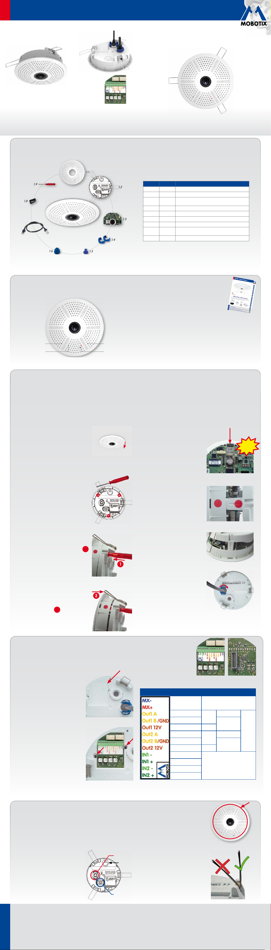
c25 Standard Delivery
for Ceilings
www.mobotix.com> Products>
32.396-003_EN_07/2016
1.9
1.8
1.7
1.6
Connection and Initial Operation of the c25
"R" key "L" key
1.2
1.3
1.4
1.5
Item Count Part Name
1.1 1 Housing (installed)
1.2 1 Back plate with spring clips (installed)
1.3 1 Main board with lens MX-B016 or MX-B036
(installed)
1.4 2 Bayonet catch, blue (installed)
1.5 1 USB plug, blue (installed)
1.6 1 Ethernet plug, blue (installed)
1.7 1 Ethernet patch cable, 50cm/19.7in, black
1.8 1 MicroSD card pre-installed (SDHC installed, SDXC
supported)
1.9 1 Disassembly tool
For information on connecting the c25, please see
the
Q25 Camera Manual, Section 2.9, «Network and
Power Connection, Additional Cables»
.
Regarding the initial operation of the c25, please
see the
Q25 Camera Manual, Chapter 3, «Initial
Operation»
and follow the instructions for wall or
ceiling mounting.
Use a suitable device for operating the camera keys (e.g., an opened
paper clip).
RecordingPower/Status
Inserting/Exchanging the SD Card
All camera models can use the integrated MicroSD card (SDXC) to record video data. In order to exchange the MicroSD card, please proceed as outlined
in the following instruction. For information on reliable SD cards, please see the MOBOTIX website www.mobotix.com> Support> MX Media Library>
Planning in the document
Caution: In order to avoid damage from electrostatic discharge, you should touch a grounded device before opening the housing of the camera (e.g.,
the blank metal at the back of a computer). This will remove any static electricity that may have built up.
1. Remove camera, remove cables
Pull the camera from its position by gently pulling
the camera downward on one side, then the
other side.
Take care to NOT let the spring clips
snap forward (this may hurt you!).
cables that are attached to the connectors on
the back side.
2. Locate the locks
In order to remove the back plate, you will need
to push the delivered disassembly tool (item1.9)
into the three holes on the back one after the
other to release the locks (see red circles in figure).
3. Remove back plate
Insert the disassembly tool into a lock and press
firmly until you feel a perceptible resistance 1.
MicroSD Card Whitelist for MOBOTIX Cameras
Remove all
. If the camera has not yet been installed, skip step1.
4. Remove/insert SD card
If a MicroSD card has been installed, gently
press with your finger as indicated by the
arrow until you hear a
click
. Then release
the SD card. The card is protruding slightly
and can be easily removed.
Insert the new MicroSD card and gently
press with your finger as indicated by the
arrow until you hear the
click
.
5. Attach back plate
Make sure that the SD card is properly
locked in place, since the card can be
damaged otherwise.
Begin by inserting
the wide lock (next to the SD card) into the
camera housing as shown. From the factory, the lock and the corresponding slot
are highlighted by
color mark
.
Make sure that the two other locks are also
properly positioned, then press the back
plate into its seat until you hear all three
locks click into place.
Click!
6. Re-connect the cables
Insert the Ethernet cable and – if installed–
the USB cable into the corresponding sockets
and secure the connectors using the blue
bayonet catches.
Gently push against the nearest spring clip to
push the lock out of its seat and to lift the back
plate from the housing 2.
Repeat the process for the two other locks and
cautiously lift the back plate from the housing.
2
Press the spring clips back and insert the
camera into its original mounting position
(see
«Installing the c25»
).
To finish, make sure that the camera image is properly aligned: If required,
cautiously turn the camera to adjust image alignment.
Installing the MX-Bus-IO-Module
For the c25, you can use the optionally available MX-Bus-IO-Module to attach MxBus devices (e.g., an MX-GPS-Box),
to attach external sensors using the signal inputs and to switch other devices via the signal outputs.
1. Insert the MX-Bus-IO-Module
On the back of the camera, remove the
sticker that protects the receptacle and the
camera’s interior from collecting dirt (see
red arrow in figure to the right).
2. Attach the connection cables
Attach the connection wires as shown in the terminal connector overview.
Terminal Connectors
MxBus
connections
MxBus
Output1A
Output1B/GND
Carefully push the module board onto the
receptacle. Secure the module board using
the two supplied Phillips screws (red arrows
in figure).
When attaching the connection wires to the
MX-Bus-IO-Module, make sure the wires
are guided to the module without tension
(you could apply a cable tie and tie the
Output112V –
Output2A
Output2B/GND
Output212V –
Input1–
Input1+
Input2–
Input2+
wires to the network cable, for example).
Installing the c25
Use the drilling template on the back for this purpose (red circle) or draw a circle with 105mm/4.13in diameter for the
cut-out. Cut out the hole for the camera, then guide the Ethernet cable and any other cables you want to attach to the
camera through the hole.
1. Connect the cables
2. Install the c25
Relay
pot.-
free
Relay
pot.-
free
–
Output1
12V selfpowered
–
Output2
12V selfpowered
Inputs
Outputs
Insert the cables into the appropriate connectors and fasten them using the blue
bayonet catches.
Make sure that the camera points into the
desired direction: The icon on the back (black
arrow) shows the "up" direction of the image.
Ethernet
"Up"
Press the spring clips back and insert the
c25 into the hole for the camera. The spring
clips will snap outwards, thus firmly holding
the camera in place.
Make sure that you only press back the
spring clips as shown in the image. Do not
press them back any further as the springs
USB
Innovations– Made in Germany
The German company MOBOTIX AG is known as the leading pioneer in network camera technology and its decentralized concept has made
high-resolution video systems cost-ecient.
MOBOTIX AG • D-67722 Langmeil • Phone: +49 6302 9816-103 • Fax: +49 6302 9816-190 • sales@mobotix.com
www.mobotix.com
may snap out of their fixtures otherwise.
Page 2
EN
Output1
Output2
Quick Install Hemispheric c25
Security-Vision-Systems
Removing the c25
1. Pull out the camera
Pull the camera from its position by gently pulling the camera downward
on one side, then the other side.
Take care to NOT let the spring clips
2. Remove the cables
Remove the cables coming from the building (network cable, USB cable,
MxBus and signal input/output wires). Pull out the camera.
snap forward (risk of injury!).
Initial Operation of the c25
The initial operation starts with connecting the power supply (see section
Cables»
in the
Q25 Camera Manual
). The first access follows the procedure described in the same manual in the
section «Initial Operation of the Camera». All other tasks require access to the camera’s user interface in the browser.
Enter the camera’s IP address into the address bar of the browser.
Configuring and Using the MX-Bus-IO-Module
1.
The camera will automatically detect an installed
MX-Bus-IO-Module (see Camera Status, System
section in browser).
The signal inputs can be used right away in the
signal input profiles
in the Setup Menu> Event
Overview. Likewise, the signal outputs can be
used in the
signal output profiles
in Admin
Menu> Hardware Configuration> Signal Out Profiles.
In addition, the signal inputs/outputs have been entered automatically
in the Admin Menu> Assign Wires dialog and can be used to control
doors and lights.
«Network and Power Connection, Additional
To use one or both signal outputs not as potential-free outputs (for relays),
but as
self-powered 12V outputs
, open the Admin Menu> Hardware
Configuration> Manage Hardware Expansions dialog. In the MxBus/
IO Board section, click on Connect for each output you want to use as
self-powered output.
2. Save the configuration
In the live image of the browser, select the Manage Settings quick control
and set Store Entire Configuration as value. The camera stores the configuration in the permanent camera memory so that the settings will be
applied at the next camera reboot.
2015 • Declaration of Conformity: www.mobotix.com> Support> Media Library> Certificates
Important Notes
Safety Warnings
• This product must not be used in locations exposed to the dangers
of explosion.
• Make sure that you install this product as outlined in the installation
instructions above.
•
When installing this product, make sure that you are only using genuine
MOBOTIX parts and MOBOTIX connection cables.
• Only install this product in suitable, solid materials that provide for a
sturdy installation of the fixing elements used.
• Electrical systems and equipment may only be installed, modified and
maintained by a qualified electrician or under the direction and supervision of a qualified electrician in accordance with the applicable electrical guidelines. Make sure to properly set up all electrical connections.
• When removing the camera from the ceiling, make sure that the spring
clips do not snap back (
•
When attaching modules to the USB connector, the
of all attached modules must not exceed 1W
• Due to the high performance of the c25, the area of the image sensor
can get quite hot, especially when the ambient temperature is also
risk of injury!
).
power consumption
.
high. This does not aect the proper functioning of the camera in any
way. This camera must not be installed within the reach of persons.
• Make sure the power supply to the camera is disconnected before
opening the camera housing (e.g., when exchanging the SD card).
• MOBOTIX products include all of the necessary configuration options
for operation in Ethernet networks in compliance with data protection
laws. The operator is responsible for the data protection concept across
the entire system. The basic settings required to prevent misuse can be
configured in the software and are password-protected. This prevents
unauthorized parties from accessing these settings.
•
Make sure that the operating temperature of 0 to +40 °C is not exceeded.
Legal Notes
You must comply with all data protection regulations for video and sound
monitoring when using MOBOTIX products. Depending on national laws
and the installation location of the c25, the recording of video and sound
data may be subject to special documentation or it may be prohibited. All
users of MOBOTIX products are therefore required to familiarize themselves
with all valid regulations and comply with these laws. MOBOTIX AG is not
liable for any illegal use of its products.
Technical Specifications
Since the c25 is identical to the Q25 for the most part, the technical data listed in the
also applies to this product. You can find the
c25 (Dierences Compared to Q25)
Lens Options
Audio features
Interfaces
Power Consumption Typ. 4W
Operating Conditions
Max. thickness for
installation
Dimensions
Materials Housing: PBT GF30
Weight approx. 212 g
B016 (180° horizontal field of view)
B036 (103° horizontal field of view)
Audio package variant (with microphone and speaker)
available
Ethernet 10/100, IPv4/IPv6, MiniUSB;
MxBus and inputs/outputs using optional accessory
IP20 (DIN EN 60529)
0 to +40 °C (DIN EN 50155)
Spring clips properly clamp down on materials from
1to 26mm/0.04 to 1.02in
Outside diameter 120mm/4.72in, total height
51mm/2.01in with B016, 56mm/2.21in with
B036, height installed 15mm/0.59in with B016,
20mm/0.79in with B036, rec. min. installation depth
55mm/2.17in
Q25 Camera Manual
as a PDF file on www.mobotix.com> Support> Manuals.
Q25 Camera Manual
in Section
«Technical Data»
MX-Bus-IO-Module
Inputs
Outputs
Add. Interfaces MxBus connections for MOBOTIX peripheral devices
Operating
Conditions
Cross-sectional
area of wires at the
terminals
Power
Consumption
2 galvanically separated inputs
(AC/DC, 0 to 48V)
Variant1 (default): 2 potential-free outputs (max. load
per pin: max. 30W or max. 1A or max. 48V AC/DC)
Variant2 (set in browser): 2 powered outputs 12VDC;
max. 50mA per output
Same as camera
0.14 mm² – 0.5 mm² (AWG 21 – 26)
Typ. 0.5W, max. 1.5W
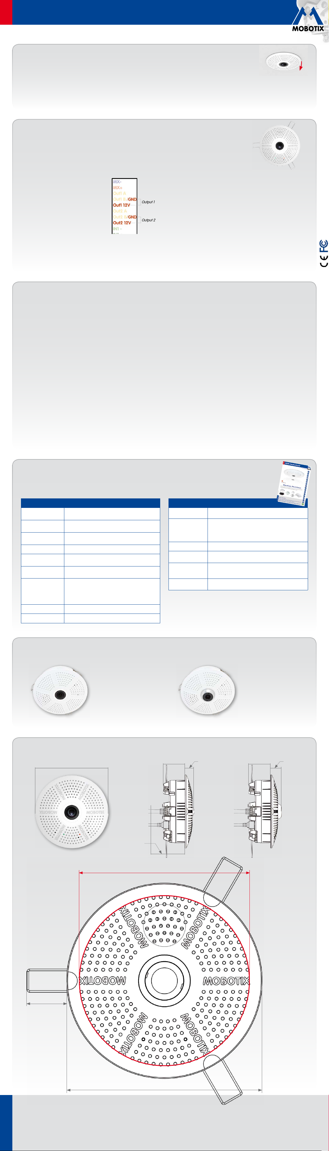
Outside diameter 120mm/4.72in
Forms of the c25
MX-c25 with lens B016 MX-c25 with lens B036
Dimensions/Drilling Template
36mm/1.42in
15mm/
0.59in
36mm/1.42in
20mm/
0.79in
c25 with lens L12
Recommended
min. instal-
lation depth
55mm/2.17in
Cut-out diameter 105mm/4.13in
c25 with lens L23
25mm/0.98in
Outside diameter 120mm/4.72in
Innovations– Made in Germany
The German company MOBOTIX AG is known as the leading pioneer in network camera technology and its decentralized concept has made
high-resolution video systems cost-ecient.
MOBOTIX AG • D-67722 Langmeil • Phone: +49 6302 9816-103 • Fax: +49 6302 9816-190 • sales@mobotix.com
www.mobotix.com
Copyright © MOBOTIX AG 2016 • Made in Germany • Technical information subject to change without notice. MOBOTIX AG and its subsidiaries do not assume any liability for technical or editorial errors or omissions contained herein.
 Loading...