

Page 1
EN
Quick Install MxDisplay+
Security-Vision-Systems
MxDisplay+: Intercom for Door Stations
MX-Display3-EXT
• IP-based intercom with touchscreen for MOBOTIX door stations
• Video Management Software for MOBOTIX systems included
• Access control: issuing, changing and disabling of RFID cards
• WiFi access point and client functionality integrated
• Flush-mounting in-wall or on-wall installation
• Fits into any MOBOTIX door station frame
The MxDisplay+ can be used as an intercom to a MOBOTIX IP video door station, but also to integrate and operate up to eight additional video sources
(cameras and door stations). When using the MxDisplay+ as an intercom, the following functions are available: live image, intercom, open door, switch
light, access mailbox, playback recordings and manage RFID cards. In addition, the MxDisplay+ can be used to configure the entire door station/camera
system and as a WiFi access point. If a wired network connection is not available, the device can also work as a WiFi client to get a network connection.
32.524-001_EN_11/2015
Delivered Parts
1.5
1.4
Item Number Part Name
1.1 1 MxDisplay+
1.2 1 Seal
1.3 1 RFID card (administrator)
1.4 1 Screwdriver
1.5 1 Allen wrench 2.5mm
Operating equipment Touchscreen with 3 soft touch function keys
Interface Ethernet, WiFi (access point, client)
Display size 3.5“, 320 x 240 pixels (CIF)
Outputs 1 potential-free
Inputs 3 self-powered inputs, ext. temperature sensor
Operating conditions Indoors, temperature range
Power supply PoE or 12 to 48V DC
Cross-sectional area of
wires at the terminals
Power input typ. 3.5W
RFID Mifare DESFire EV1
WiFi IEEE 802.11b/g/n, 2.4 GHz band
Ethernet PoE (IEEE 802.3af, class2)
1.1
1.2
1.3
Technical Specifications
(multiple functions), 2 status LEDs
output (max. load per pin: max.
30W or max. 1A or max. 48V AC/DC)
0 to +40 °C/+32 to +104 °F
0.14 mm² – 0.5 mm² (AWG 21 – 26)
Dimensions
Order No.: MX-Display3-EXT
99mm/3.89in
99mm/3.89in
37mm/
1.46in
99mm/3.89in
Important Notes
• The MxDisplay+ is only to be used together with the MOBOTIX
original frames and the in-wall and on-wall housings.
• The MxDisplay+ must not be installed in metallic materials, since
this will prevent the RFID antenna from working properly and may
even destroy the RFID chip.
• Electrical installation: Electrical systems and equipment may only
be installed, modified and maintained by a qualified electrician
or under the direction and supervision of a qualified electrician in
accordance with the applicable electrical guidelines. Make sure
to properly set up all electrical connections.
• Network security: MOBOTIX products include all of the necessary
configuration options for operation in Ethernet networks in compliance
with data protection laws. The operator is responsible for the data
protection concept across the entire system. The basic settings
required to prevent misuse can be configured in the software and
are password-protected. This prevents unauthorized parties from
accessing these settings.
• This product must not be used in locations exposed to the dangers
of explosion.
• The installation of this product must only be on or in suitable solid
materials that allow for a stable installation of the fixing devices.
• When powering MxBus devices, you need to use either PoE or an
48VDC power supply.
• Make sure the device is not operated outside of its operating
temperature range of 0 to +40 °C/+32 to +104 °F.
Available Accessories for the FlatMount Frame
When using the FlatMount Frame, the MxDisplay+ can be installed in-wall either with an in-wall housing or without (cavity).
1. FlatMount Frame
124mm/4.88in
Order No.: MX-OPT-FlatMount-EXT-PW (white)
Order No.: MX-OPT-FlatMount-EXT-BL (black)
112mm/4.41in
2. In-wall housing
124mm/4.88in
Order No.: MX-OPT-FlatMount-Box-EXT-IN
112mm/4.41in
Available Accessories for the Single Frame
When installing the MxDisplay+, you can choose between two frames: the single frame and the FlatMount Frame. Using the single frame, you have
the choice between on-wall and in-wall mounting. Note that the space is quite limited when using on-wall mounting.
1. Single frame
Order No.: MX-OPT-Frame-1-EXT-PW (white)
Order No.: MX-OPT-Frame-1-EXT-BL (black)
2. Single on-wall and in-wall housings
• On-wall housing
Order No.: MX-OPT-Box-1-EXT-ON-PW (white)
Order No.: MX-OPT-Box-1-EXT-ON-BL (black)
131mm/5.16in
143mm/5.63in
126mm/4.96in
117mm/4.61in
138mm/5.43in
• In-wall housing
Order No.: MX-OPT-Box-1-EXT-IN
129mm/5.08in
Power Supply and Network Connection
Power Supply
To supply power to the MxDisplay+, the following options exist:
• PoE (Power over Ethernet) using a CAT.5 to CAT.7 installation cable
• using an external power supply (12 to 48V DC) that is connected to the MxDisplay+ by a two-wire cable
Using PoE as a power supply, all you need is a PoE switch or a MOBOTIX NPA PoE Adapter. When integrating MxDisplay+ into an existing network,
using a PoE switch with several PoE ports is recommended – especially when several PoE-supplied end devices are to be connected. When powering
MxBus devices, you need to use either PoE or an 48VDC power supply.
Network Connection
To connect MxDisplay+ to a network, the following options exist:
• together with power supply via PoE (see above)
• with Ethernet installation cable, but without PoE power supply
• via an existing WiFi network
Recommendation
The easiest and, more importantly, most reliable network connection for the MxDisplay+ is to use the network cabling for power supply and network
connectivity (PoE). By nature, WiFi networks are bound to experience temporary disruptions. Therefore, it is not recommended to use a WiFi network
connection for the MxDisplay+ if you need a reliable and permanently available door station intercom.
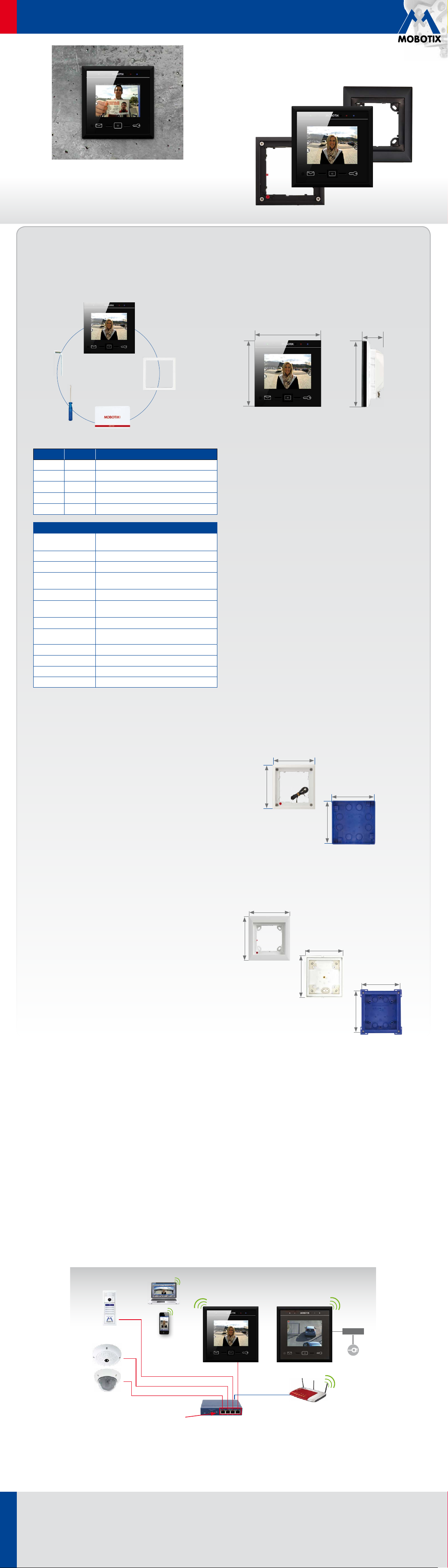
Installation Example with Two MxDisplay+ Units
MxDisplay+ 1
Door station(s)
Cameras
PoE-powered ports
PoE switch & router
MxDisplay+1 is connected via a failsafe PoE connection and serves as remote station for the door station as well as WiFi access point for
additional remote stations (iPhone, iPad). MxDisplay+2 is farther away and uses the WiFi network of the DSL router. It is used primarily as video
management system to monitor and configure the installed cameras.
MxDisplay+ 2
Power supply
24V DC
DSL router
Innovations - Made in Germany
The German company MOBOTIX AG is known as the leading pioneer in network camera technology and its decentralized concept has made high-resolution video
systems cost-ecient.
www.mobotix.com
MOBOTIX AG • Security-Vision-Systems • D-67722 Langmeil • Phone: +49 6302 9816-103 • Fax: +49 6302 9816-190 • sales@mobotix.com
Page 2
EN
Quick Install MxDisplay+
Security-Vision-Systems
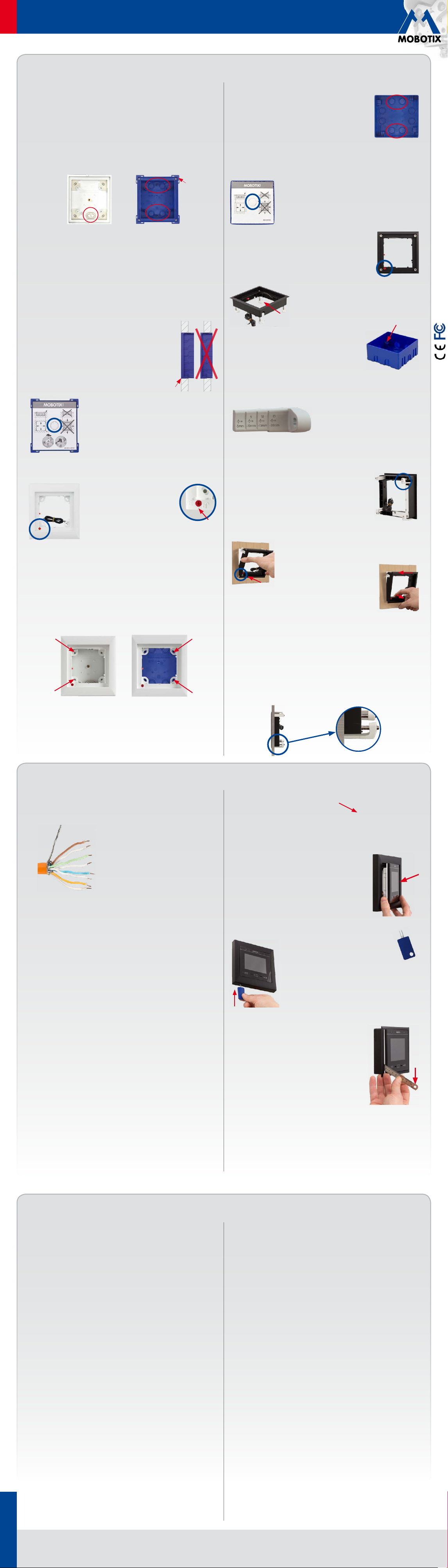
Installing the Housing and the Frame
Single Frame with In-Wall or On-Wall Housing
1. Lead Cable into the Housing
On-wall/in-wall: The housing has two (on-wall) or several (in-wall)
cable inlets. Pierce through the required inlet with, for example, a
screwdriver. When using the on-wall housing, lead the cable into the
housing. When using the in-wall housing, make sure that you pierce
through the inlet that is closest to the required cable connection, i.e.,
use the upper inlet for a two-wire cable and the lower for an installation
cable.
Bar
On-Wall In-Wall
2. Insert Housing
On-wall: Drill four holes and insert dowels, if necessary (use the on-
wall housing as a template to mark the holes). Screw on the housing.
In-wall: Prepare the opening for the in-wall housing (W x H x D: 117 x
129 x at least 52 mm). You can use the reverted housing as a template
to mark the opening. Lead the cable into the housing. Make sure that
the cable is long enough (about 40cm/16in), so that
the wires can be connected easily to the MxDisplay+.
Excess cable can be stored in the housing by winding
it up in a spiral. Insert the housing. Connect the inwall housing in such a way with the underground
that the bars attached to the corners of the housing
(see fig. at the right) are still visible and that the front
edge of the housing lines up precisely with the wall.
Set the protective cardboard cover (included with the
delivered parts) into the housing before pushing it into
the wall cavity. This prevents cement from entering
the interior of the housing. After you have installed
the housing into the wall, you can easily remove the
carton by pushing through the pre-cut opening and
pulling it out.
3. Attach Single Frame
On-wall/in-wall: When attaching the
frame, make sure that the arrow on
the red knob (theft protection) points
at the “open lock” icon and that the
frame is positioned in such a way
that the red knob is on the bottom
left corner of the frame.
Caution: In situations, in which a theft protection is not necessary,
e.g., indoor installations, do not activate the theft protection (the
red knob remains in the “open lock” position). If you twist the
!
knob by mistake, you have to be able to attach a battery (9V
DC). Otherwise, the frame cannot be released!
Secure the frame with the on-wall or the in-wall housing and make
sure that you do not overtighten the screws included with the FlatMount
Frame.
On-Wall
In-Wall
FlatMount Frame with On-Wall Housing
1. Lead Cable into the Housing
See
«Lead Cable into the Housing»
several cable inlets are possible here as well, make
sure that you pierce the inlet that is closest to the
required cable connection.
2. Insert Housing
See
«Insert Housing»
opening (Wx Hx D): 112 x 112 x 60 mm.
3. Attach FlatMount Frame
Make sure that the arrow on the red knob points at
the “open lock” icon and that the FlatMount Frame
is positioned so that the red knob is on the bottom
left.
and make sure that you do not overtighten them.
By tightening the screws, the clamping brackets
automatically engage into the notches of the
housing.
In-wall Installation in Cavities (without In-Wall Housing)
Installations in cavity walls without in-wall housings are possible in
materials that are 3 to 25mm/0.18 to 1in thick.
the FlatMount Frame to the correct length according to the thickness of
the material. Replace the short clamping brackets that are attached to
the FlatMount Frame by the ones you just shortened.
2. To facilitate the installation, there are notches for
the clamping brackets on three corners of the FlatMount
Frame. After you have attached the long clamping
brackets to the frame, turn three of the clamping
brackets so that they fit into the notches. Turn the
fourth clamping bracket (on the corner without notch)
downwards.
slightly pull the lower part of the frame back out. This
causes the upper part of the frame to “fall” into the
opening.
Caution: In situations, in which a theft protection is not necessary,
e.g., indoor installations, do not activate the theft protection (the
red knob remains in the “open lock” position). If you twist the
!
knob by mistake, you have to be able to attach a battery (9V
DC). Otherwise, the frame cannot be released!
4. Tighten the screws and make sure that you do not overtighten them.
The endings of the clamping brackets hold the FlatMount Frame to the
surface.
(In-wall) on the left. Measurements for the installation
As with the single frame installation on the left, set the
protective cardboard cover (included with the delivered
parts) into the housing before pushing it into the wall
cavity. This prevents cement from entering the interior
of the housing.
Position the clamping brackets at the ends of the
screws in such a way that the screws are easily
led past the notches of the housing when you
attach the FlatMount Frame. After attaching the
frame, tighten the screws
3. Insert the FlatMount Frame into the opening. Make
sure that the red knob is on the lower left corner and
that the arrow on the red knob points
at the “open lock” icon. Insert the lower
left edge of the frame first, then follow
with the lower right edge. After that,
on the left. Since
1. Prepare the opening for the FlatMount
Frame (W x H: 107x 107 mm). Measure
the thickness of the material. Cut the long
clamping brackets that are included with
2015 • Declaration of Conformity: www.mobotix.com> Support> Media Library> Certificates
Connecting and Inserting MxDisplay+ into the Frame
Power Supply and Network Connection with Installation
Cable
1. Prepare Installation Cable
Cut the installation cable to length, strip it
and separate the twisted wire pairs into eight
individual wires. Make sure that you can still
identify the wire pairs later on. Cut the wire
ends to length, pull the shield mesh together
and twist it so that you can attach it onto the
contact surface later on.
2. Connect Wires
Open the cover on the back of the MxDisplay+. Push the individual wires
through the holes and insert them into the terminals of the lower row
according to the color codes on the sticker. Make sure that the white
wire of the white-blue wire pair changes position with the white-green
pair (see fig.). Fasten the shield mesh onto the contact surface and
close the cover.
Note: To remove a wire, unlock the terminal by pressing with the
screwdriver (included with delivery) into the opening above the wire.
Then pull out the wire.
2. Set Up MxDisplay+ as WiFi Client
Once the MxDisplay+ is running, it has to be set up as a WiFi client
(Installation> Display Configuration> WiFi).
Inserting the MxDisplay+ into a Frame
Make sure that the seal has been positioned properly on
the back of the MxDisplay+ and the protective foil has
been removed. Insert the MxDisplay+ into the frame with
its right side first (this applies for both the single frame
and the FlatMount Frame). Then push the MxDisplay+
on the left side into the frame until it clicks into place.
Detaching the MxDisplay+ from a Frame
Single Frame
To detach the MxDisplay+, insert the key
(included with the delivery of the single frame)
into the two slots on the lower left corner of the
frame and push upwards. The MxDisplay+ is released
on the left side, so you can pull it from the frame.
3. Connect Installation Cable
Connect the installation cable to a patch cable and to the PoE switch
and establish the power supply.
External Two-Wire Power Supply, WiFi Network
1. Connect Two-Wire Cable
Cut the wire ends to length. Open the cover on the back of the MxDisplay+
and push the wire ends through two of the openings of the single-wire
sealing. Then insert the wire ends into the holes of the power terminal
(GND and VCC, see fig. at top of next column). Close the cover.
Initial Operation
Make sure that all cameras you want to use with the MxDisplay+ are running
firmware version 4.2.3 or higher. For updating the firmware on door
stations, see the
Support> Manuals> Software> Compact Guides).
To update the MxDisplay+ software, start a browser, enter the IP address of
the MxDisplay+ (user admin, password meinsm) and then select Update
System Software.
Note: By factory default, the MxDisplay+ has been set to run as DHCP
client. In addition, it has a local 10.x IP address (see sticker on the back)
with a network mask of 255.0.0.0.
Starting Up Door Station(s) and Setting Up MxDisplay+ as Remote
Station
The complete startup using only MxDisplay+ will be possible with a later
software version. Until this is the case, follow the same steps outlined in
Chapters 2 to 4
Support> Manuals> IP Video Door Station).
1. Power: All devices have to be connected to the network and supplied
with power.
2.
Auto configuration: Carry out the auto configuration at the door station
(see
Part2
master and then carry out the auto configuration on that door station.
The auto configuration is completed by entering the Super PIN at the
access modules (KeypadRFID or BellRFID).
3. Access modules: Set up the access modules that are used, including
training the RFID cards, entering the contact/people/PIN numbers (if
applicable) and configuring the bell buttons on the BellRFID modules
(see the corresponding sections in the
MxDisplay+: Reboot the MxDisplay+ by simultaneously holding the
Envelope, Home and Key buttons until a beep sounds five times in a
Compact Guide: Firmware Update
of the
T25 System Manual Part2
Chapter2.1.3, «Start the Auto Configuration»
). When using several door stations, choose one door station as a
(www.mobotix.com>
(www.mobotix.com>
in
T25 System Manual
T25 System Manual Part2
).
FlatMount Frame
Insert the ruler (included with the FlatMount Frame)
into the slit on the lower left in such a way that the
upper part of the ruler is on the same level as the
lower part of the MxDisplay+ image area. Push the
outer end of the ruler downwards (see fig. on the
right). The MxDisplay+ is released on the left side,
so you can pull it from the frame.
row. Start the Installation Wizard via Settings> Installation to change
the camera access password and all desired bells. You can keep all
other settings.
Important: You have to enter the Super PIN as the password for the
door stations. The Super PIN is the number you entered during the
auto configuration. After this, you ought to define any existing door
contacts and door lock switches for each door station, deactivate the
auto configuration and activate the recording (Settings> Installation>
Camera Configuration). When using several MxDisplay+ units, you
can set the parameters that you want to be the same on all devices
(e.g., lock specific functions). After you have set these parameters, you
can apply the configuration to all other MxDisplay+ units (Settings>
Installation> Display Configuration> Manage Settings). Reboot all
other MxDisplay+ units (as described above) and, if applicable, configure
individual settings for each MxDisplay+, e.g., which bells should sound
on which MxDisplay+.
Note: Other cameras besides door station cameras can be integrated
into the system using the installation wizard. Make sure that the cameras
are running as DHCP client (this is the factory setting of camera software
releases 4.2.3 and higher) and that the factory default admin password
meinsm is still valid.
Integrating MxDisplay+ into an Existing Door System
1. Integrate the MxDisplay+ into the network with the MOBOTIX door
stations and cameras as described in the supplied
Install
. Establish the power supply (PoE or power adapter).
2. After the has been connected, it shows the date and time (stand-by
mode). Tap on the screen and select the Installation Wizard). Follow
the individual steps and assign the desired bells to the MxDisplay+.
This can be changed later on in Settings > Installation > Display
Configuration> Assign Door Bells.
MxDisplay+ Quick
Copyright © MOBOTIX AG 2015 • Made in Germany • Technical information subject to change without notice.
www.mobotix.com
MOBOTIX AG • Security-Vision-Systems • D-67722 Langmeil • Phone: +49 6302 9816-103 • Fax: +49 6302 9816-190 • sales@mobotix.com
 Loading...