

Page 1
Mx-D16
32.803-005_EN_10/2017
Quick Install
D16 DualDome
Variants
D16
• Mx6 system platform, H.264 support
• Recording on internal MicroSD card (SDXC, SDHC installed)
• Audio integrated (microphone and speaker)
• Sensor for temperature and shock detector(*) integrated
• PIR detector integrated
• Can be extended exibly using sets for outdoor applications
• Easy installation at building corners and poles using the
Corner and Pole Mount (accessory)
• Use the Vandalism Set for surveillance at extremely critical locations
• Weatherproof and robust camera housing (IP54, IK10)
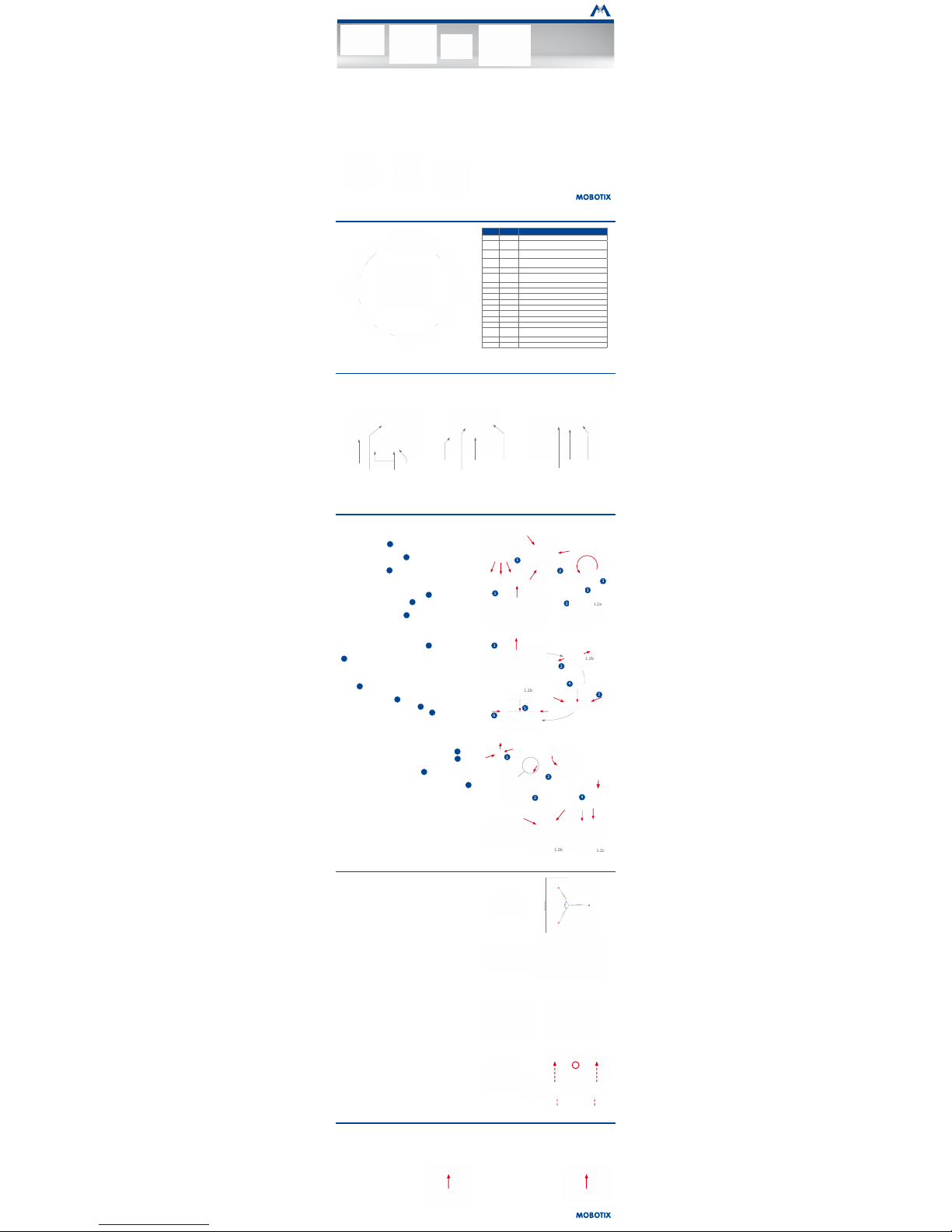
Standard Delivery D16
1.9
1.6
1.5
1.3
1.4
1.10
1.11
1.12
1.13
1.1
1.2b
1.2a
1.2c
1.8
1.15
1.14
1.7
Item Count Part Name
1.1 1
Camera housing
1.2a 1
Lens units with lenses (freely adjustable,
to be ordered
separately
)
1.2b 1
Pano lens bridge (for 180° Panorama,
to be ordered
separately
, pre-installed)
1.2c 1
Fix lens bridge (for one day and one night lens,
to be
ordered separately
, pre-installed)
1.3 1
Standard dome for D16 Body
1.4 1
Enlarged XL dome for D16 complete cameras (Pano and
Fix) and part of the delivery of the Pano/Fix lens bridges
1.5 1
Cable cover
1.6 1
Ethernet cable
1.7 1
Hinged ferrite
1.8 1
MicroSD card (SDXC, SDHC pre-installed)
1.9 1
Custom tool with magnet
1.10 1
Outer shell
1.11 3
Stainless steel washers 5.3 mm dia.
1.12 3
Dowels 8 mm
1.13 3
Stainless steel wood screws 4.5x60 mm with Torx head
TX20
1.14 1
Torx wrench TX20
1.15 1
Allen wrench 3 mm
Connections and Initial Operation of the D16
You can nd detailed information on the installation and connections of the D16 in the
D15 Camera Manual
(PDF, available on www.mobotix.com >
Support > Manuals).
Please note that the boot options of this camera have changed compared to its predecessor (see
«Boot Options of the D16» on page 2
). Regarding
the rest of the initial operation of the D16, please see the
D15 Camera Manual
in
Chapter 3, «Initial Operation»
.
Slot for MicroSD card
Network
connector (*)
USB
L key
(magnetic,
inside housing)
Connectors
Dome thread
Camera
housing
Lenses
Outer shell
LEDs/PIR
Dome
* To suppress electromagnetic interferences, attach the enclosed hinged ferrite (item 1.7) directly behind the RJ45 connector of the camera's network
patch cable, see illustration.
Preparing the D16 for Installation
To facilitate the installation of the camera, you should complete the following tasks before actually installing the camera.
Preparatory Steps
Make sure that the condensed water outlets are pointing downwards when
planning the installation 1.
Remove the outer shell by pressing the magnetic custom tool into the three
holes of the outer shell one by one 2. Gently li the shell near each hole
to loosen the shell from its seats.
Next, unscrew the dome 3.
Insert the Individual Lens Units (1.2a)
Remove the center lock screw and the washer 1.
Insert the lens units into the seatings 2.
Insert the center lock screw and the washer and lightly tighten the screw
to keep the lens units
1.2a
in place 3. Do not overtighten the lock screw
so you can adjust the lens units later on.
Insert the Lens Bridge (1.2b/c)
Remove the center lock screw and the washer 1.
Disassemble the lens bridge by removing the two Allen screws with washers
2
(Pano lens bridge
1.2b
shown, similar for Fix lens bridge
1.2c
).
Insert the two brackets for the lens bridge into the seatings of the camera
housing 3.
Insert the center lock screw and the washer and lightly tighten the screw
to keep the brackets in place 4.
Insert the lens bridge between the brackets 5, insert the two Allen screws
with the washers and lightly tighten the screws 6. Do not overtighten
the two screws so you can adjust the lens bridge later on.
Connect the Sensor Cables
Remove the protective covers of the image sensor connectors 1.
Connect the camera's sensor cables according to the color codes 2. While
doing so, avoid twisting the sensor cables as much as possible.
Press the cable into the groove of the board 3. Take care that the wires
are not bent sharply at the plug, but that they are running in an arc.
Press the protective covers onto the connectors until they click into place 4.
Insert the Lenses (Lens Bridges Only)
Remove the protective covers of the lens mounts and screw in the lenses.
Lens focus will be adjusted aer installing the camera and bringing it into
service (see
«Initial Operation of the D16»
).
3
1
2
1
1.2a
3
2
1.2b
2
1
3
4
6
1.2b
5
1
4
4
2
3
1.2b
1.2c
Lens units
(individually adjust-
able)
2 image sensors on
Pano lens bridge
2 image sensors on
Fix lens bridge
With Outdoor Wall Mount With Corner and Pole Mount
and Outdoor Wall Mount
With Vandalism Set
Mounting Options of the D16
Installation on Walls or Ceilings Without Accessories
Aer drilling the holes for xtures (see
«Drilling Template for Installation
Without Accessories»
), attach the housing of the D16 at the designated
position using dowels and screws, then connect the cabling. Once the
power supply has been established, you will adjust the lens units or bridges
(whichever applies) and the lenses' focus (see
«Initial Operation of the D16»
).
Finally, you will install the dome and the outer shell.
Installation With Outdoor Wall Mount (Accessory)
Remove the cover plate of the Outdoor Wall Mount. Aer drilling the holes
for xtures (see
«Drilling Template for Installation Without Accessories»
),
attach the Outdoor Wall Mount at the designated position using dowels
and screws, then lead the cabling into the mount. Next, connect the cabling
and install the camera on the cover plate of the Outdoor Wall Mount using
the supplied screws. Then attach the cover plate with the camera to the
Outdoor Wall Mount.
For more information, please see the
D15 Camera Manual, Section 2.4,
«Mounting the Camera with Outdoor Wall Mount»
.
Installation With Corner and Pole Mount and Outdoor Wall Mount
(Accessory)
Lead the cabling from the rear through the Corner and Pole Mount and
attach it at the corner of a building or a pole (using steel straps). Then
attach the Outdoor Wall Mount to the Corner and Pole Mount.
The remaining installation of the D16 follows the steps under
«Installation
With Outdoor Wall Mount (Accessory)»
above.
Installation of the Vandalism Set (Accessory)
Remove the outer shell and the dome (see
«Preparing the D16 for Instal-
lation»
). Screw in the reinforced dome and hold the stainless steel ring
of the Vandalism Set in position to mark the holes for drilling (the bulge
in the steel ring covers the LED/PIR dome – see red circle in gure on the
right). Drill the holes for the mounting screws (or the dowels, whichever
applies), then apply the stainless steel ring and fasten it using the supplied
security screws.
75 mm/2.95 in
75 mm/2.95 in
75mm/2.95in
1
2
0
°
Dia. 205mm/8.07in
Universal 6MP Dome Camera With
Two Lenses for Ceiling, Wall and Pole
Mounting
MOBOTIX 6MP camera for exible use in indoor and
outdoor applications, available as complete D16
DualDome (Day or Night) with lenses 6D/N/L036 to 237 and
with dierent lens bridge options.
More information:
www.mobotix.com > Products > Outdoor Cameras > D16
Inserting/Exchanging the SD Card
All camera models can use the integrated MicroSD card (SDHC) to record video data. In order to exchange the MicroSD card, please proceed as outlined
in the following instruction. For information on reliable SD cards, please see the MOBOTIX website www.mobotix.com > Support > MxMedia Library >
Planning in the document
MicroSD Card Whitelist for MOBOTIX Cameras
.
When replacing the SD card, make sure that recording has been deactivated in the browser (Admin Menu > Storage > Storage on External File Server /
Flash Device; activate recording again in the same dialog aer exchanging the card).
1. Remove the SD Card
Remove the outer shell and the cable cover of
the camera. If a MicroSD card has been installed,
gently press with your nger as indicated by
the arrow until you hear a
click
. Then release
the SD card. The card is protruding slightly and
can be easily removed.
2. Insert the SD Card
Insert the MicroSD card and gently press with
your nger as indicated by the arrow until you
hear another
click
. Make sure that the SD card
is fully inserted. Re-attach the cable cover and
the outer shell of the camera.
Click!
Click!
*: with rmware version 5.0.1 and higher
Page 2
MOBOTIX AG
Kaiserstrasse
D-67722 Langmeil
Tel.: +49 6302 9816-103
Fax: +49 6302 9816-190
sales@mobotix.com
www.mobotix.com
Declaration of Conformity: www.mobotix.com > Support > MxMedia Library > Certicates
MOBOTIX, the MX logo, MxControlCenter, MxEasy, MxPEG and MxActivitySensor are trademarks of
MOBOTIX AG registered in the European Union, the U.S.A., and other countries • Information subject to
change without notice • MOBOTIX does not assume any liability for technical or editorial errors or omissions
contained herein • All rights reserved • © MOBOTIX AG 2017
Initial Operation of the D16
The initial operation starts with connecting the power supply (see section
«Network and Power Connection, Additional Cables»
in the
D15 Camera Manual
).
The rst access follows the procedure described in the same manual in the
«Initial Operation of the Camera»
section. All other tasks require access to
the camera's user interface in the browser. Enter the camera’s IP address into the address bar of the browser.
1. Enter Type of Lens Bridge and Lenses
Open the Admin Menu > Hardware
Conguration>ImageSensorConguration dialog and select the type
of lens bridge you installed. Next, select
the lenses you installed for the image sensors in
HardwareConguration>LensConguration.
This step is required so the camera can apply the
proper distortion correction methods for the
installed lenses.
2. Adjust the Lens Focus
Remove the dome before proceeding.
Check the live image from the camera in the browser. Activate the focusing
aid in the browser (Focusing Aid quick control, Activated value).
Carefully turn the lens by hand in clockwise or counter-clockwise direction until the red area of the focusing aid is as small as possible.
Except
D16-Panorama/180°:
Switch to the other image sensor (Camera Selection
quick control) and repeat the process, if required.
Once the focus is adjusted properly, deactivate
the focusing aid again (Focusing Aid quick
control, Disabled value).
Note: Due to the lens eect of the dome, the
focus of the
B237 tele lens
is shiing slightly
once the dome has been mounted. Before
mounting the dome, the tele lens should be
turned about
90° in counter-clockwise direction
(as seen from the lens'
front). Make sure that you check the focus of the live image in your browser
with the dome installed and re-adjust the lens, if required.
3. Reboot the Camera and Reset the Image Settings
Reboot the camera (Admin Menu > General Tasks > Reboot) and then
reset the image settings and all views to the factory defaults (Manage
Settings > Load Image Factory Defaults quick control). If required, adjust
the image settings.
Only Pano/Fix:
Adjust the dual image using the on-screen con-
trol (g. on the right; see also
D15 Camera Manual, «Adjusting
the Panorama Image (D16-Pano Only)»
).
4. Savetheconguration
In the browser, select the Manage Settings quick control and set Store
EntireConguration as value. The camera stores the conguration in
the permanent camera memory so that the settings will be applied at the
next camera reboot.
Technical Specications D16
Lens Options
MX-B036 to MX-B237 (20 to 135 mm in 35 mm format),
103° to 15° horizontal angle of view
Min. Illumination
Color sensor (6MP): 0.1 Lux at 1/60 s, 0.005 Lux at 1 s
Black&White sensor (6MP): 0.02 Lux at 1/60 s,
0.001 Lux at 1/1 s
Image Sensor 1/1.8“ CMOS, 6MP, progressive scan
Max. Image Size
Color: 3072x2048 (6MP), 6144x2048 (12MP)
Black&White: 3072x2048 (6MP), 6144x2048 (12MP)
Image Formats
3072x2048 (6MP), 2592x1944 (5MP), 2048x1536 (QXGA), 1920x1080
(Full-HD), 1280x960 (MEGA), 1280x720 (HD), 1024x768, 800x600,
768x576 (D1-PAL), 704x576 (TV-PAL), 640x480, 384x288, 320x240,
160x120, custom formats
Max. Frame Rate
• MxPEG (max): 42@HD (1280x720), 34@Full-HD, 24@QXGA,
15@5MP, 12@6MP, 6@2x6MP
• M-JPEG (max): 26@HD (1280x720), 13@Full-HD, 9@QXGA,
5@5MP, 4@6MP, 2@2x6MP
• H.264 (max): 25@Full-HD, 20@QXGA
Video Codec MxPEG, M-JPEG, JPEG, H.264
Internal DVR MicroSD card (SDXC, SDHC pre-installed)
External
VideoRingBuer
Directly on NAS or PC/Server, no additional recording soware
required
Soware(Included) MxManagementCenter video management soware
Image Processing
Backlight compensation, automatic white balance, image distortion correction, panorama correction, video motion detection,
MxActivitySensor
Virtual PTZ Digital pan/tilt/zoom, continuous up to 8X
Alarm/Events
Video Motion detection, MxActivitySensor, external signals, tem-
perature sensor, PIR, microphone, shock detector (with rmware
version 5.0.1 and higher), notication via e-mail, FTP, IP telephony
(VoIP, SIP), visual/sound alarms, pre- and post-alarm images
Microphone and
Speaker
Integrated microphone and speaker
Audio Functions Lip-synchronous audio, two-way communication, audio recording
Interfaces
Ethernet 100Base-T, MiniUSB;
inputs/outputs and RS232 via accessories
Video Telephony
VoIP/SIP, two-way communication, remote controlling using key
codes, event notication
Security
User/group management, HTTPS/SSL, IP address lter, IEEE 802.1x,
intrusion detection, digital image signature
Certications
EN55032:2012, EN55022:2010; EN55024:2010, EN61000-6-1:2007,
EN61000-6-3:2007+A1:2011, EN61000-6-4:2007+A1:2011, AS/ NZS
CISPR22:2009+A1:2010
Power Supply
Year-round Power-over-Ethernet (IEEE 802.3af);
PoE class variable
Power Consumption Typ. 5 W
Protection Classes
IP54 and IK10
IP65 and IK10 with Outdoor Wall Mount
IP66 and IK10+ with Vandalism Set
Operating Conditions –30 to 60 °C/–22 to 140 °F
Dimensions/Weight
Diameter x Height: 205 x 108 mm (D16), 205 x 125 mm
(D16-Panorama/180°, D16-DNight); weight: approx. 750 g/1.65 lb
(including lenses)
Standard Delivery
Housing (high-resistance composite, PBT-PC), white, two shock-resistant domes (transparent), mounting supplies, wrenches,
50 cm/19.69 in patch cable, soware, MicroSD card (installed)
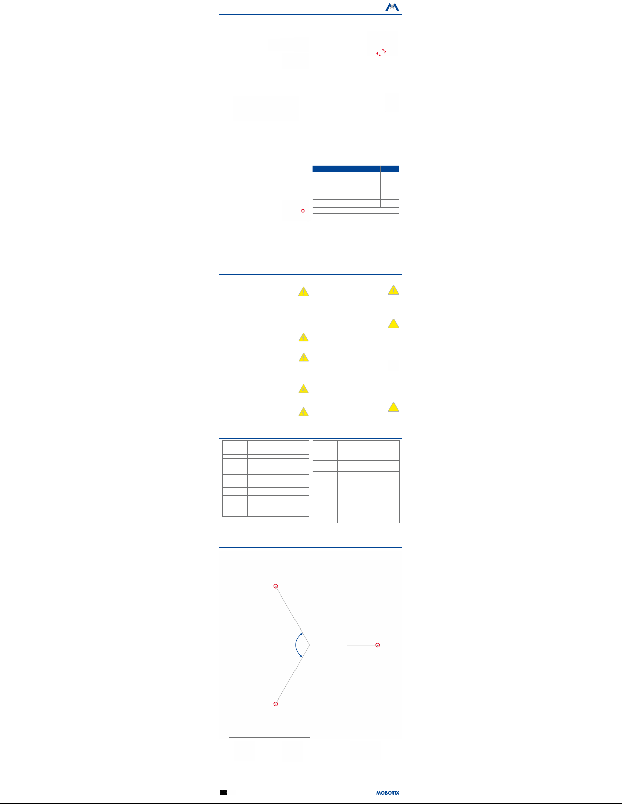
Drilling Template for Installation Without Accessories
75 mm/2.95 in
75 mm/2.95 in
75mm/2.95in
1
2
0
°
Dia.205mm/8.07in
Manuals and drilling templates: www.mobotix.com > Support > Manuals > IP Camera Systems > DualDome D16
Camera
without
accessories
Vandalism Set
Outdoor Wall Mount
Important Notes
Safety Warnings
Notes on Installing:
• This product must not be used in locations exposed to
the dangers of explosion.
• Make sure that you install this product as outlined in
Chapter 2, «Installation»
of the corresponding manual.
A faulty installation can damage the camera!
•
When installing this product, make sure that you are only
using genuine MOBOTIX parts and MOBOTIX connection
cables.
•
Only install this product on suitable, solid materials that
provide for a sturdy installation of the xing elements
used.
Electrical installation: Electrical systems and equipment may
only be installed, modied and maintained by a qualied
electrician or under the direction and supervision of a qualied
electrician in accordance with the applicable electrical guidelines. Make sure to properly set up all electrical connections.
Electrical surges: MOBOTIX cameras are protected against
the eects of small electrical surges by numerous measures.
These measures, however, cannot prevent the camera from
being damaged when stronger electrical surges occur. Special
care should be taken when installing the camera outside of
buildings to ensure proper protection against lightning, since
this also protects the building and the whole network infrastructure.
Never touch the lenses: Due to the high performance of the
D16, the area of the image sensor can get quite hot, especially
when the ambient temperature is also high. This does not
aect the proper functioning of the camera in any way. For
this reason, the product must not be installed within the reach
of persons without the dome.
Powerobeforeopeningthecamera: Make sure the power
supply to the camera is disconnected before opening the camera housing (e.g., when inserting or exchanging lenses, lens
units and SD cards).
Network security: MOBOTIX products include all of the necessary conguration options for operation in Ethernet networks in compliance with data protection laws. The operator
is responsible for the data protection concept across the entire
system. The basic settings required to prevent misuse can be
congured in the soware and are password-protected. This
prevents unauthorized parties from accessing these settings.
Legal Notes
Legal aspects of video and sound recording: You must comply
with all data protection regulations for video and sound monitoring when using MOBOTIX products. Depending on national
laws and the installation location of the D16, the recording of
video and sound data may be subject to special documentation
or it may be prohibited. All users of MOBOTIX products are
therefore required to familiarize themselves with all applicable
regulations and to comply with these laws. MOBOTIX AG is not
liable for any illegal use of its products.
Disposal
Electrical and electronic products contain many valuable
materials. For this reason, we recommend that you dispose
of MOBOTIX products at the end of their service life in accordance with all legal requirements and regulations (or deposit
these products at a municipal collection center). MOBOTIX
products must not be disposed of in household waste! If the
product contains a battery, please dispose of the battery sep-
arately (the corresponding product manuals contain specic
directions if the product contains a battery).
Disclaimer
MOBOTIX AG does not assume any responsibility for damages,
which are the result of improper use or failure to comply to the
manuals or the applicable rules and regulations. Our General
Terms and Conditions apply. You can download the current
version of the General Terms and Conditions from our website at www.mobotix.com by clicking on the COS link at the
bottom of every page.
§
§
Boot Options of the D16
By default, the camera starts as DHCP client and automatically tries to get
an IP address from a DHCP server. To start the camera in a mode dierent
from the default mode, you can activate the boot menu of the camera.
1. Preparing the Camera
• Disconnect the camera's power supply.
•
Make sure that you have the custom tool with magnet (item 1.8) at hand.
• Reconnect the power supply of the camera.
2. Activating the Boot Menu
The red LED lights up 5 to 10 seconds aer establishing the power supply and will stay on for 10 seconds.
Briey press the magnet of the custom tool onto the spot
indicated by the red circle in the gure. The camera enters
the boot menu, ready for selecting one of the boot options.
The LED now ashes once and repeats the ash signal aer pausing for one
second (the number of ashes indicates the current boot option). To go to
the next boot option, briey press the magnet again onto the designated
spot (< 1 sec). Aer the last boot option, the camera returns to the rst
option (LED ashes once).
LED
ashes
Boot
Option
Meaning
Audio
Conrmation*
1 x Not used Not available on this camera model. —
2 x
Factory
Defaults
Starts the camera with factory defaults
(factory default IP address, users and
passwords will not be reset).
Boing
3 x
Automatic IP
Address
Starts the camera as DHCP client and
tries to obtain an IP address from a DHCP
server. If a DHCP server cannot be found or
no IP address can be obtained, the camera
starts with its factory default address.
Boing Boing
4 x
Recovery
System
Starts the camera with the recovery system, e.g., in order to recover from a failed
update of the camera soware.
Alarm Sound
*Only on cameras with audio option and installed speaker.
3. Selecting a Boot Option
Press the magnet longer (> 2 sec) onto the indicated position. The camera
conrms the selection by ashing rapidly three times. You can now remove
the magnet. Aer 20 sec, the camera will conrm the selection by playing
a sound according to the table above.
If nothing is selected, the camera will resume its normal boot process
aer a certain time.
 Loading...