

Page 1
Bullet Camera
MOBOTIX MOVE BC-4-IR
Quick Install
Page 2
Bullet Camera BC-4-IR
This guide is for quick installing and connecting the MOBOTIX MOVE BC-4-IR Bullet IP Camera. You can find detailed
information on the installation and connections in the Camera Manual (PDF, available on www.mobotix.com >
Support > Download Center > Documentation > Manuals).
Installation Notices
• This camera must be installed by qualified personnel and the installation should conform to all local codes.
• This camera contains replaceable batteries. To prevent explosion risks, confirm the battery type before
replacement. Dispose of used batteries in accordance with the local regulations.
• To use an external power supply, please contact the camera manufacturer to confirm that the power supply uses
the same power specifications as the camera. The power supply must comply with the LPS requirements.
Installation
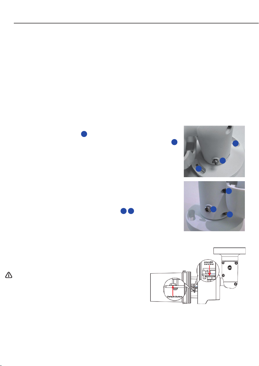
• Place the camera at the installation location. On the ceiling / wall, mark the
position of the two screw holes
• If the screw holes are blocked by the camera body, loosen the three screws
but do not detach it. Then rotate the camera body to reach the screw holes.
• At the center of the two marked holes, drill a 30 mm diameter (radius as 15mm)
cable entry hole. Then drill a hole slightly smalle r than the supplied pla stic screw
anchor on each marked screw hole.
• Thread the All-in-One cable of the camera through the cable entry hole. Refer to
chapter Camera Cabling for cable connections.
• Match the two screw holes of the camera with the plastic screw anchors at the
installation location. Insert the plastic screw anchors into the two drilled holes,
and then fasten the camera with the supplied M4x31 self-tapping screws.
• Use a cross screwdriver to loosen the four screws
figures but do not detach them. Rotate the camera and point the camera to a
desired direction. Lastly, tighten the four screws to secure the camera.
1
of the camera.
2 3
indicated in the right
2
,
1
2
1
2
3
2
microSD Card Slot / Default Button
microSD Card Slot
Insert the microSD card into the card slot to store videos and
snapshots. Do not remove the microSD card when the camera
is powered on.
NOTE: It is not recommended to record with the microSD card
for 24/7 continuously, as it may not be able to support
long term continuous data read/write. Please contact the
manufacturer of the microSD card for information regarding
the reliability and the life expectancy.
Default Button
Press the default button with a proper tool for at least 20 seconds to restore the system.
Page 3

Camera Cabling
Please follow the instructions below for cable connections.
Power Connection
Use a DC 12V / AC 24V adaptor and connect it to the 2-pin terminal block of the All-in-One cable and the power
outlet. Alternatively, connect the Ethernet cable to the RJ-45 connector of the All-in-One cable, and plug the other
end of the cable to a Power Sourcing Equipment (PSE) switch.
Ethernet Cable Connection
Connect one end of the Ethernet cable to the RJ-45 connector of the All-in-One cable, and plug the other end of
the cable to the network switch or PC.
NOTE: Check the status of both power and network activity indicator LEDs. If either LED is unlit, please check the
corresponding connection.
All-in-One Cable
No. Connector Pin Definition Remarks
1 RJ-45 - For network and PoE connections
2 Audio I/O
3 BNC (Optional) - For analog video output
Alarm I/O
4
(5-pin Terminal Block)
Power (DC 12V / AC 24V)
5
(2-pin Terminal Block)
Green Audio Out / Mic Out (Line Out)
Pink Audio In / Mic In (Line In)
1 Alarm In 2+
2 Alarm In 3 Alarm In 1+
4 Alarm Out 5 Alarm Out +
1 DC 12V − AC 24V 1 Power connection
2 DC 12V + AC 24V 2
Alarm connection
Two-way audio transmission
Page 4

Bullet Camera BC-4-IR
Before Login to the Camera
A client program will be automatically installed to the PC when connecting to the camera. Before logging in
to the camera, ensure downloading the ActiveX control is allowed by either changing the ActiveX controls
and plug-ins or setting Internet’s security level to default.
ActiveX Controls and Plug-ins Settings Internet Security Level
Step 1: Start the Internet Explorer (IE).
Step 2: Select <Tools> from the main menu of the browser.
Then click on <Internet Options>.
Step 3: Click on the <Security> tab and select <Internet>, and
click on <Custom level> to change ActiveX settings.
Step 4: Set “ActiveX controls and plug-ins” items to <Prompt>
or <Enable>.
Camera Login
The default IP address of the camera is: 10.x.x.x By default, the camera starts as a DHCP client and automatically
tries to get an IP address from a DHCP server.
Login ID & Password
Key in the camera’s IP address in the URL bar of the web browser window and hit “Enter”. Enter the default username
(admin) and password (meinsm) in the prompt request dialogue. The password must be changed upon the first login.
Install the ActiveX Control
• A er connecting to the camera, the request for installing the ActiveX control will appear just below the URL bar.
• Right click on the information bar and click on <Install ActiveX Control…> to permit ActiveX control installation.
• In the pop-up security warning window, click on <Install> to star t downloading Viewer so ware on the PC.
• Click on <Finish> a er V iewer installation is completed.
Step 1: Start the IE Internet Explorer (IE).
Step 2: Select <Tools> from the main menu of the browser.
Then click on <Internet Options>.
Step 3: Click on the <Security> tab and select <Internet>.
Step 4: Down the page, click on <Default Level> and <OK> to
confirm the setting. Close the browser window, and
open a new one later for accessing the IP camera.
EN_06/18
MOBOTIX AG • Kaiserstrasse • D-67722 Langmeil • Tel.: +49 6302 9816-0 • Fax: +49 6302 9816-190 • sales@mobotix.com • www.mobotix.com
MOBOTIX, the MX Logo, MxControlCenter, MxEasy, MxPEG and MxActivitySensor are trademarks of MOBOTIX AG registered in the European Union, the U.S.A. and in
other countries • For a complete product overview and a current price list, see the MOBOTIX website • Sold only to distributors or commercial clients • Subject to
change without notice • MOBOTIX do not assume any liability for technical or editorial errors or omissions contained herein • All rights reserved • © MOBOTIX AG 2018
 Loading...