

Page 1
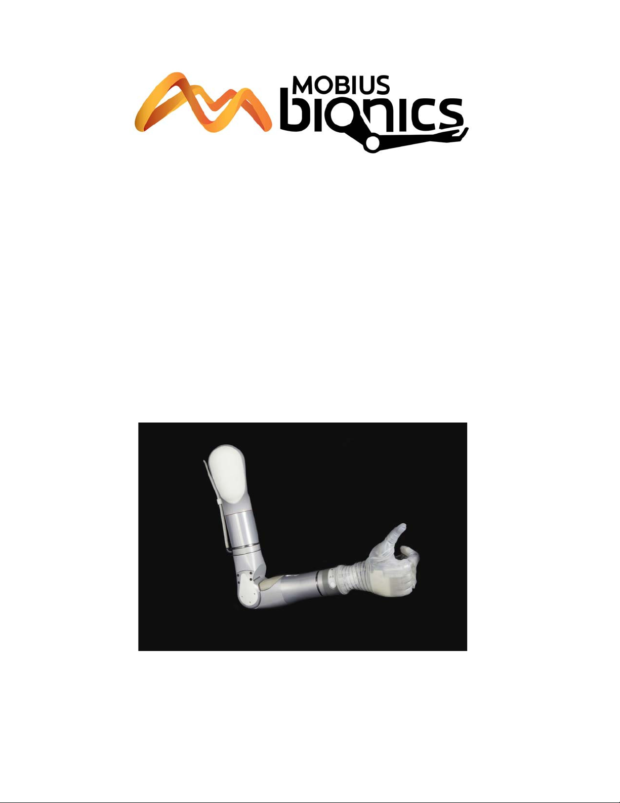
LUKE Arm
User Guide
Part Number: LU-09012-001
Revision: 1.8
Date: December 05, 2016
Manufactured by:
Mobius Bionics
470 Commercial Street
Manchester, NH 03101
www.mobiusbionics.com
Page 2

Copyright
Copyright © 2016, Mobius Bionics LLC. All rights reserved.
Mobius Bionics LLC proprietary rights are included herein. This document contains
Mobius Bionics confidential information and may not be copied, transferred, or
disclosed, except as authorized by Mobius Bionics.
Trademarks
Bluetooth® is a registered trademark of Bluetooth SIG.
Wi-Fi® is a registered trademark of Wi-Fi Alliance.
Page 3

Contents
About This Guide
How to Use This Guide ................................................................................ 11
Conventions ................................................................................................ 12
Terminology................................................................................................ 14
Acronyms ................................................................................................... 14
Contacting Technical Support....................................................................... 15
Chapter 1 LUKE Arm System
Indications for Use ....................................................................................... 17
LUKE Arm System ...................................................................................... 18
Arm Types ............................................................................................ 19
Shoulder Configuration (SC) .............................................................. 19
Humeral Configuration (HC).............................................................. 19
Radial Configuration (RC).................................................................. 19
Batteries and Holster .............................................................................. 21
Internal Battery ................................................................................ 21
External Battery ............................................................................... 22
External Battery Holster .................................................................... 22
Battery Chargers and Charging Dock....................................................... 23
Charging Pad................................................................................... 24
AC Adapter ..................................................................................... 24
Charging Dock................................................................................. 25
ACI (Arm Control Interface) Module......................................................... 26
Input and Output Control Devices............................................................ 27
IMUs (Inertial Measurement Units)...................................................... 27
EMG (Surface EMG Electrodes).......................................................... 27
Pressure Switches............................................................................. 28
Rocker Switches............................................................................... 28
Pressure Transducers ........................................................................ 29
Linear Transducers ........................................................................... 29
Tactor ............................................................................................. 30
Contents
Chapter 2 Safety
Safety Guidelines - Arm................................................................................ 31
Electromagnetic Interference (EMI) Safety....................................................... 34
Safety Guidelines - Battery............................................................................ 35
Rev 1.8 -- Use or Disclosure of Data Contained on this Page is Subject to the Restrictions on the Inside Title Page of this Document 12/5/163
Page 4

Contents
Chapter 3 Arm Types and User Controls
System Battery Types................................................................................... 38
User Controls and Wrist Display.................................................................... 38
Power ON/OFF Button Location............................................................. 39
Turning the Arm ON and OFF ................................................................ 40
Wrist Display ......................................................................................... 40
Low Battery Icon and Low Battery Alert ......................................... 41
System Fault Icon .......................................................................... 41
Arm Mode LED and Grip Select LEDs ............................................ 42
Display Button ................................................................................. 43
Displaying the Battery Charge Level................................................... 43
Changing the Display Brightness........................................................ 44
Swapping IMUs................................................................................ 44
IMU LED Status ..................................................................................... 45
Hand Open Button................................................................................. 47
Orienting The Arm While Pressing The Hand Open Button ................. 48
Chapter 4 Setting Up the Arm
Installing IMUs............................................................................................. 49
Installing the IMU to the Shoe Clip .......................................................... 50
Installing the Shoe Clip to Your Shoe....................................................... 52
Location and Orientation of the IMUs ...................................................... 53
Waking a Sleeping IMU................................................................................ 53
Donning (Putting On) the Arm ...................................................................... 54
Chapter 5 Using the Arm
Key Concepts.............................................................................................. 56
Switching vs. Motion .............................................................................. 56
Operating Modes ................................................................................... 57
IMU - Walk Detect.................................................................................. 58
IMU - Angle Limit Detect ........................................................................ 58
Mode Change Interlock........................................................................... 59
Zeroing the IMUs ................................................................................... 59
Safe Operation of the System ....................................................................... 60
What To Do If the Arm Is Not In Proper Working Order............................ 60
Arm Is Not in Proper Working Order ................................................. 60
Unsure When Using the Arm............................................................. 60
Grasp Release .................................................................................. 61
Doffing the Arm ............................................................................... 61
Safe Motions ......................................................................................... 62
Taking It Slow........................................................................................ 62
Practicing Safe Operation of the System .................................................. 63
Lifting Heavy Objects ............................................................................. 63
Initializing the Arm....................................................................................... 64
Re-Initializing the Arm.................................................................................. 65
Improper Shutdowns.................................................................................... 65
4 Use or Disclosure of Data Contained on this Page is Subject to the Restrictions on the Inside Title Page of this Document -- Rev 1.8
Page 5

Contents
Operating Modes and Motions ...................................................................... 66
Standby Mode (No Motion) ..................................................................... 66
Hand Mode Motions............................................................................... 66
Opening or Closing the Hand............................................................ 67
Compound Wrist Motions ................................................................. 67
Rotating the Wrist ............................................................................ 69
Selecting a Grip ..................................................................................... 69
Power Grip (Grip Select LED 1)......................................................... 70
Tool Grip (Grip Select LED 2) ........................................................... 71
Fine Pinch Closed Grip (Grip Select LED 3) ........................................ 72
Fine Pinch Open Grip (Grip Select LED 4).......................................... 72
Lateral Pinch Grip (Grip Select LED 5) ............................................... 73
Chuck Grip (Grip Select LED 6)......................................................... 75
Grip Detents .................................................................................... 75
Arm Mode Motions ................................................................................ 75
SC Arm Motions .............................................................................. 76
Elbow Flexion - Extension (HC Arm) .................................................. 79
Humeral Internal - External Rotation (HC Arm) ................................... 80
Doffing (Removing) the Arm ......................................................................... 80
Chapter 6 Charging the Batteries
Battery Charging Safety ............................................................................... 82
Testing the Internal Battery Charge Level....................................................... 82
Charging the Internal Battery ........................................................................ 83
Testing the External Battery Charge Level...................................................... 85
Charging the External Battery ....................................................................... 86
Removing the External Battery from the Holster ................................. 88
Installing the External Battery in the Holster........................................ 88
Testing the IMU Battery Charge Level ........................................................... 89
Charging the IMU Battery............................................................................. 90
Chapter 7 Maintaining and Troubleshooting the Arm
Maintaining the Arm .................................................................................... 93
Removing and Replacing the Fingernails, Finger Covers and Hand Cover ... 94
Removing and Replacing Fingernails .................................................. 95
Removing and Replacing Finger Covers ............................................. 96
Removing and Replacing Hand Cover ................................................ 97
Cleaning the Arm................................................................................... 98
Troubleshooting the Arm............................................................................ 100
LUKE Arm System Alerts ..................................................................... 100
Troubleshooting ................................................................................... 101
Rev 1.8 -- Use or Disclosure of Data Contained on this Page is Subject to the Restrictions on the Inside Title Page of this Document 12/5/165
Page 6

Contents
Appendix A Technical Specifications
Arm Specifications..................................................................................... 107
Battery Specifications................................................................................. 112
AC Adapter Specifications.......................................................................... 113
Charging Pad Specifications........................................................................ 114
Arm Radio Specifications............................................................................ 115
Appendix B Guidance and Manufacturer’s Declaration
Electromagnetic Environment...................................................................... 117
Electromagnetic Emissions .................................................................... 117
Electromagnetic Immunity..................................................................... 118
Recommended Separation Distances ........................................................... 121
Essential Performance ................................................................................ 122
6 Use or Disclosure of Data Contained on this Page is Subject to the Restrictions on the Inside Title Page of this Document -- Rev 1.8
Page 7

Contents
List of Figures
Figure 1. Arm Types ............................................................................ 20
Figure 2. Internal Battery ......................................................................21
Figure 3. External Battery ..................................................................... 22
Figure 4. External Battery Holster..........................................................23
Figure 5. Charging Pad for IMU Battery................................................. 24
Figure 6. AC Adapter........................................................................... 24
Figure 7. Charging Dock ...................................................................... 25
Figure 8. ACI Module ........................................................................... 26
Figure 9. Example Inertial Measurement Unit ......................................... 27
Figure 10. Example EMG .......................................................................27
Figure 11. Example Pressure Switch ........................................................ 28
Figure 12. Example Rocker Switch .......................................................... 28
Figure 13. Example Pressure Transducer ................................................. 29
Figure 14. Example Linear Transducer ....................................................29
Figure 15. Example Tactor Output Device................................................ 30
Figure 16. Pinch Point Areas ..................................................................34
Figure 17. Power Button and LED - SC, HC, and RC Arms With External
Battery Only .......................................................................... 39
Figure 18. Power Button and LED - SC and HC Arms with Internal Battery 40
Figure 19. Wrist Display ......................................................................... 41
Figure 20. Hand Open Button ................................................................ 47
Figure 21. Attaching the IMU to the Shoe Clip......................................... 51
Figure 22. Attaching the Shoe Clip to the Shoe........................................ 52
Figure 23. Hand Open Button ................................................................ 61
Figure 24. Hand Open and Hand Closed ................................................. 67
Figure 25. Compound Wrist Motions ....................................................... 68
Figure 26. Rotating the Wrist .................................................................. 69
Figure 27. Power Grip............................................................................ 70
Figure 28. Tool Grip .............................................................................. 71
Figure 29. Fine Pinch Closed Grip........................................................... 72
Figure 30. Fine Pinch Open Grip ............................................................ 72
Figure 31. Lateral Pinch Grips ................................................................74
Figure 32. Chuck Grip............................................................................ 75
Figure 33. Moving the Hand Up or Down................................................ 77
Figure 34. Moving the Hand Left or Right................................................ 77
Figure 35. Moving the Hand Forward or Backward................................... 78
Figure 36. Voluntary Elbow Positioning (VEP) .......................................... 79
Figure 37. Elbow Flexion - Extension .......................................................79
Figure 38. Humeral Internal - External Rotation........................................ 80
Figure 39. Internal Battery Charging Port and Status Icon .........................84
Figure 40. Testing the External Battery Charge Level................................ 85
Figure 41. External Battery Charging Dock and Status LEDs ..................... 87
Figure 42. Removing and Replacing the External Battery .......................... 89
Figure 43. Charging the IMU Battery....................................................... 90
Figure 44. Lateral Pinch Grip - Fully Open ............................................... 94
Figure 45. Removing and Replacing the Fingernails .................................. 96
Rev 1.8 -- Use or Disclosure of Data Contained on this Page is Subject to the Restrictions on the Inside Title Page of this Document 12/5/167
Page 8

Contents
Figure 46. Lace - Securing Hand Cover ................................................... 97
Figure 47. Removing and Replacing the Finger and Hand Covers ..............98
Figure 48. Dimensions of Shoulder Configuration (In Centimeters) ........... 110
Figure 49. Dimensions of Humeral Configuration (In Centimeters)............ 111
Figure 50. Dimensions of Radial Configuration (In Centimeters) ............... 111
8 Use or Disclosure of Data Contained on this Page is Subject to the Restrictions on the Inside Title Page of this Document -- Rev 1.8
Page 9

Contents
List of Tables
Table 1. Arm System Icons ................................................................. 12
Table 2. Text Conventions.................................................................. 13
Table 3. Terminology ......................................................................... 14
Table 4. Acronyms............................................................................. 14
Table 5. Arm and Battery Types ......................................................... 38
Table 6. Arm Mode and Grip Select LEDs............................................ 42
Table 7. Wrist Display Battery Charge Levels ....................................... 43
Table 8. IMU LED Status.................................................................... 45
Table 9. Control Types - Switching vs. Motion ..................................... 56
Table 10. Arm and Operating Modes..................................................... 57
Table 11. Hand Mode — Motions ......................................................... 66
Table 12. Grip Select LEDs .................................................................. 69
Table 13. Arm Mode — Motions........................................................... 76
Table 14. Internal Battery Charging Port and Status Icon ........................ 84
Table 15. External Battery Charge Level................................................ 86
Table 16. External Battery Charging Dock Status LEDs........................... 87
Table 17. IMU Battery Charging LED Status .......................................... 91
Table 18. Troubleshooting - Try This First............................................ 101
Table 19. Troubleshooting - Wrist Display and System Faults................. 102
Table 20. Troubleshooting - Arm Function........................................... 104
Table 21. Troubleshooting - Power and Battery Charging...................... 105
Table 22. Arm System Specifications................................................... 107
Table 23. Operating Environmental Range........................................... 107
Table 24. Transport and Storage Environmental Range......................... 108
Table 25. Service Life Specifications.................................................... 108
Table 26. Mass of Arm Configurations................................................. 109
Table 27. Dimensions of Arm Configurations ....................................... 109
Table 28. Battery Charge and Operation Times.................................... 112
Table 29. Power Specifications - Internal Battery .................................. 112
Table 30. Power Specifications - External Battery ................................. 112
Table 31. Power Specifications - IMU Battery....................................... 113
Table 32. AC Adapter Specifications ................................................... 113
Table 33. Charging Pad Specifications................................................. 114
Table 34. Arm Radio Specifications..................................................... 115
Table 35. Guidance and Manufacturer’s Declaration -
Electromagnetic Emissions ................................................... 117
Table 36. Guidance and Manufacturer’s Declaration -
Electromagnetic Immunity.................................................... 118
Table 37. Recommended Separation Distances (Part I).......................... 121
Table 38. Recommended Separation Distances (Part II) ......................... 122
Rev. 1.8 -- Use or Disclosure of Data Contained on this Page is Subject to the Copyright Restrictions on the Inside Title Page of this Document 9
Page 10

Contents
10 Use or Disclosure of Data Contained on this Page is Subject to the Copyright Restrictions on the Inside Title Page of this Document -- Rev. 1.8
Page 11

About This Guide
The intent of this guide is to help guide you in the use of the LUKE arm system.
Read this guide before using the arm.
This guide is shipped with the LUKE arm system.
How to Use This Guide
To learn about the arm and how to use the arm read the chapters in the table
below.
Read To Learn About...
Chapter 1 Overview — Provides a summary of the arm and arm parts.
Chapter 2 Safety — Provides WARNINGS and CAUTIONS on using the
arm and batteries.
Chapter 3 Arm Types and User Controls — Provides information about
arm types, batteries, and user controls and displays.
Chapter 4 Setting Up the Arm— Tells you how to install the IMUs and don
the arm.
Chapter 5 Using the Arm— Provides information on key concepts as well
as how to safely initialize the arm, change operating modes, and
command hand and arm motions.
Chapter 6 Charging the Batteries — Provides steps on how to charge all
batteries.
Chapter 7 Maintenance and Troubleshooting — Tells you how to
maintain the arm as well as troubleshoot problems.
Rev 1.8 -- Use or Disclosure of Data Contained on this Page is Subject to the Restrictions on the Inside Title Page of this Document r11
Page 12
About This Guide
Conventions
Table 1 describes the arm system icons and Table 2 describes text conventions used
throughout this guide.
Table 1. Arm System Icons
Icon Meaning Description
Alert Alerts you to potential injury
hazards. Obey all safety messages
that follow this symbol to avoid
possible injury.
Information Note Notice is used to address practices
not related to personal injury.
CAUTION Cautions indicate a hazardous
situation which, if not avoided, could
result in minor or moderate injury.
WARNING Warnings indicate a hazardous
situation which, if not avoided, could
result in death or serious injury.
Read This Guide Used to instruct you to refer to this
guide prior to using the LUKE arm
system.
Electrically Isolated
Equipment
Radio Transmitter Indicates that equipment contains a
Disposal of
Equipment
Indicates Type BF equipment which
is electrically isolated and can safely
contact a person’s skin without the
risk of electric shock.
radio transmitter.
Indicates that equipment should not
be disposed of in the trash.
12 Use or Disclosure of Data Contained on this Page is Subject to the Restrictions on the Inside Title Page of this Document -- Rev 1.8
Page 13
Icon Meaning Description
Recycle Equipment Indicates that equipment should be
recycled.
Use Indoors Identifies electrical equipment
designed for indoor use and should
be kept dry.
Conventions
Meets Class II
Safety
Requirements
MR Unsafe Indicates that equipment is not
Table 2. Text Conventions
Convention Appearance in Text Example
Key concepts and
Appear in bold type. Inertial Measurement
emphasized text
Book titles, directories,
Appear in italic typeface. LUKE Arm User Guide
pathnames, and filenames
Identifies equipment that meets the
safety requirements specified for
Class II equipment according to IEC
61140.
compatible with magnetic resonance
(MRI) environment.
Unit
Rev 1.8 -- Use or Disclosure of Data Contained on this Page is Subject to the Restrictions on the Inside Title Page of this Document 12/5/1613
Page 14

About This Guide
Terminology
Table 3 describes the terminology used in this guide to describe the arm, socket,
and accessories.
Table 3. Terminology
Arm Refers to the arm hardware in isolation.
Prosthesis Refers to the combination of the socket and the arm.
Arm System Refers to the socket, arm, and all related accessories.
Acronyms
Table 4 lists the acronyms used in this guide.
Table 4. Acronyms
Ter m Description
Acronym Description
ACI Arm Control Interface — Controls the interface between you and
the Master Arm Controller.
EMG Electromyograph — A sensor that is placed on the skin and senses
the activation signal of a muscle.
EMI Electromagnetic Interference — Interference to the arm’s
electronics caused by external electrical sources.
HC Humeral Configuration — A type of arm.
IMU Inertial Measurement Unit — A control input that is placed on top
of a foot or lower appendage.
LED Light Emitting Diode — A light that displays a status.
MAC Master Arm Controller — The main processing unit of the arm.
RC Radial Configuration — A type of arm.
SC Shoulder Configuration — A type of arm.
SOC State of Charge — The battery charge level.
USB Universal Serial Bus — A standard way for a computer to talk to
other devices.
VEP Voluntary Elbow Positioning — A type of arm motion of the
LUKE arm.
14 Use or Disclosure of Data Contained on this Page is Subject to the Restrictions on the Inside Title Page of this Document -- Rev 1.8
Page 15

Contacting Technical Support
To contact technical support use the following address, web site URL or telephone:
Mobius Bionics
470 Commercial Street
Manchester, NH 03101
www.mobiusbionics.com
603-239-3834
855-MOBIUS1 (855-662-4871)
Contacting Technical Support
Rev 1.8 -- Use or Disclosure of Data Contained on this Page is Subject to the Restrictions on the Inside Title Page of this Document 12/5/1615
Page 16

About This Guide
16 Use or Disclosure of Data Contained on this Page is Subject to the Restrictions on the Inside Title Page of this Document -- Rev 1.8
Page 17

LUKE Arm System
This chapter provides an overview of the LUKE arm system which includes the
socket, arm, batteries, AC Adapter, charging pad, and arm inputs and outputs.
Prior to using the LUKE arm system you must have met with your prosthetist.
During the meeting(s) the prosthetist will have performed a number of steps such as:
• design and build a custom socket to attach the arm
• pick the arm configuration and arm parts to best fit your needs
• set up and configure the arm
• allow you to test the arm system in a controlled setting
Once the prosthetist feels that you have met all demands in order to use the arm
they will allow you to use the arm. You should clearly understand how the
prosthetist has set up your arm prior to using the arm.
1
Indications for Use
The LUKE arm system consists of a prosthetic arm and accessories which are used
by a certified prosthetist to create a full upper extremity prosthesis indicated for
individuals, age 18 years and older, who have partial or full upper limb amputations
or congenital defects. The device is used to assist in activities of daily living (ADLs).
Rev 1.8 -- Use or Disclosure of Data Contained on this Page is Subject to the Restrictions on the Inside Title Page of this Document r17
Page 18

Chapter 1: LUKE Arm System
LUKE Arm System
The LUKE arm system is comprised of a specific arm type and several accessories
depending on the arm type. The arm system is described below.
Do not take apart or change the arm or connected parts. This could lead to
harm.
Based on your arm’s type and setup you may not have some of the following
parts.
Note the following concerning the LUKE arm system:
• The arm is internally powered (when under battery power).
RISK OF DEATH OR SERIOUS HARM
• The arm is designated Class II (when plugged into the AC Adapter).
• The arm and all body worn accessories are Type BF applied parts.
The IMUs have an IP57 rating. The other body worn components of the arm
system, when installed and covers are in place, have an IP52 rating. The IP
rating specifies the strength of the enclosure against solids (such as dust) and
liquids. An IP52 rating provides resistance to light rain and fine dust. An IP57
rating provides resistance to fine dust and submersion to depths of 1 m.
18 Use or Disclosure of Data Contained on this Page is Subject to the Restrictions on the Inside Title Page of this Document -- Rev 1.8
Page 19

Arm Types
LUKE Arm System
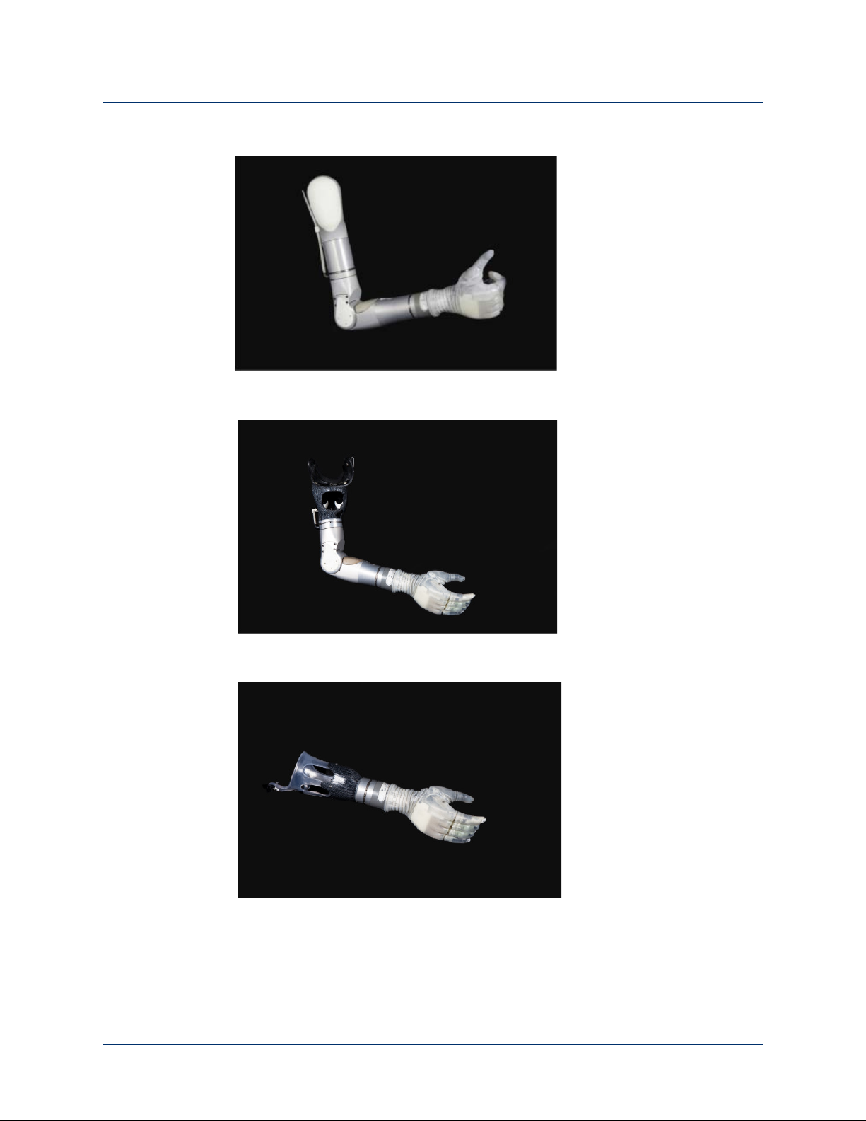
Your LUKE arm is one of the three types listed below and shown in Figure 1. Your
prosthetist will have chosen the arm type that best fits your needs and set up the
arm for the right or left side as well as proper length.
Shoulder Configuration (SC)
This arm type is for those amputees with little or no residual limb or for those
amputees with limited movement or other restricting factors in their residual limb.
Humeral Configuration (HC)
This arm type is for those amputees with a residual limb below the shoulder but not
including the elbow.
Radial Configuration (RC)
This arm type is the shortest of the three and is for amputees with a residual limb
below the elbow.
Rev 1.8 -- Use or Disclosure of Data Contained on this Page is Subject to the Restrictions on the Inside Title Page of this Document 12/5/1619
Page 20
Chapter 1: LUKE Arm System
Shoulder Configuration (SC)
Humeral Configuration (HC)
Radial Configuration (RC)
Figure 1. Arm Types
20 Use or Disclosure of Data Contained on this Page is Subject to the Restrictions on the Inside Title Page of this Document -- Rev 1.8
Page 21
Batteries and Holster
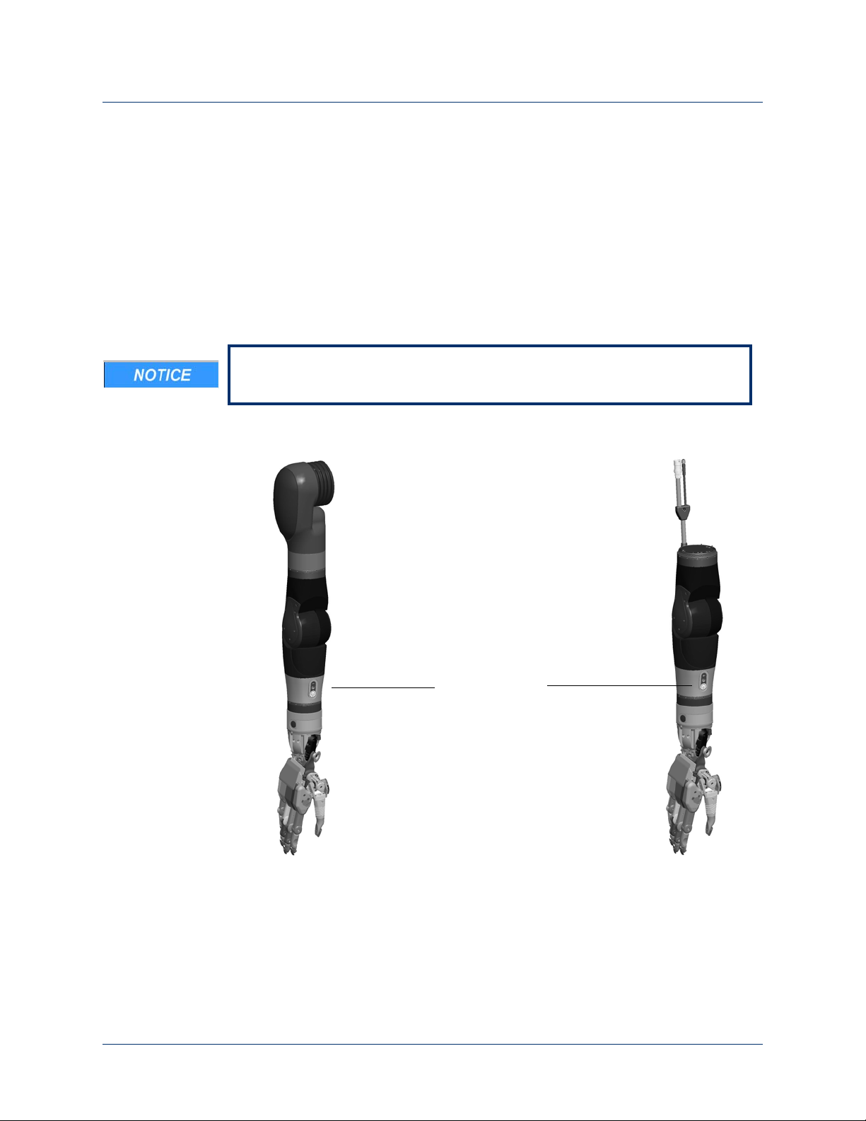
Internal Battery
Shoulder Configuration (SC)
Humeral Configuration (HC)
SC and HC Arms
(Inside the Arm)
There are two battery types used to power the arm. Which battery type is used
depends on your arm type and how your prosthetist configured the power to the
arm. The two batteries are:
Internal Battery
This battery may be used to power the SC and HC arms and is located within the
arm’s forearm. See
Depending on how your prosthetist configured your arm you may not have an
internal battery.
Figure 2. Internal Battery
LUKE Arm System
Figure 2.
Rev 1.8 -- Use or Disclosure of Data Contained on this Page is Subject to the Restrictions on the Inside Title Page of this Document 12/5/1621
Page 22

Chapter 1: LUKE Arm System
External Battery
SC, HC, and RC Arms
(Outside the Arm)
External Battery
This battery, see
Figure 3, is normally worn on a belt or in a pocket and is used in
one of two ways:
• In SC and HC arms, with an internal battery, it may be used to supplement
power to the arm.
• In RC arms and in SC and HC arms, without an internal battery, it is used
standalone to power the arm.
The external battery is used with an external battery holster to power the arm. See
External Battery Holster for more information.
Figure 3. External Battery
External Battery Holster
The external battery is mounted in a holster which in turn can be clipped to a belt or
worn in a pocket. See
the external battery is in either the vertical or horizontal position. There are two
versions of the holster; one with an ON/OFF button and power LED and one
without. For more information see
22 Use or Disclosure of Data Contained on this Page is Subject to the Restrictions on the Inside Title Page of this Document -- Rev 1.8
Figure 4. The belt clip can be attached to the holster so that
Power ON/OFF Button Location.
Page 23
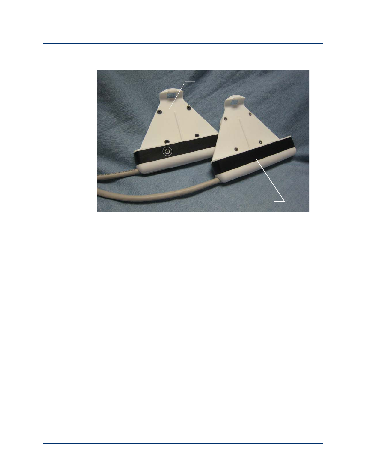
Figure 4. External Battery Holster
Battery Holster with ON/OFF button
Battery Holster without ON/OFF button
LUKE Arm System
Battery Chargers and Charging Dock
There are three components used for charging the batteries: a charging pad, an AC
Adapter, and a charging dock. The AC Adapter is used with the charging dock to
charge the external battery. To charge an internal battery, the AC Adapter plugs
directly into the arm.
Rev 1.8 -- Use or Disclosure of Data Contained on this Page is Subject to the Restrictions on the Inside Title Page of this Document 12/5/1623
Page 24
Chapter 1: LUKE Arm System
Charging Pad
AC Adapter
Charging Pad
A wireless charging pad is provided in order to charge the IMU battery.
shows the charging pad.
Figure 5. Charging Pad for IMU Battery
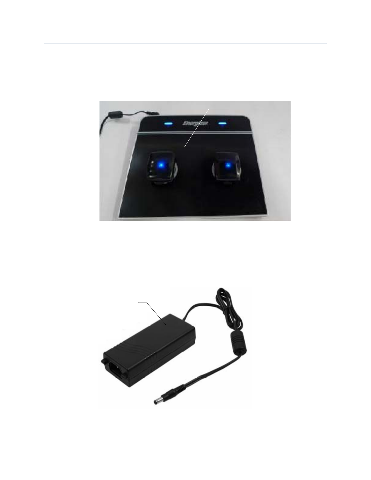
AC Adapter
Figure 5
The AC Adapter is used with the external battery charging dock and to directly
charge the internal battery within the arm. The AC Adapter comes with a line cord
for use in your country.
Figure 6 shows the AC Adapter.
Figure 6. AC Adapter
24 Use or Disclosure of Data Contained on this Page is Subject to the Restrictions on the Inside Title Page of this Document -- Rev 1.8
Page 25
LUKE Arm System
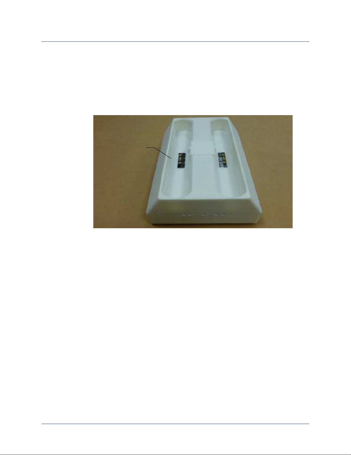
Charging Dock
Charging Dock
The charging dock is used to charge the external battery. The charging dock has
two slots allowing you to charge two batteries at once and is powered by the AC
Adapter. When charging the battery you should remove the battery from its holster
and place it in the charging dock.
Figure 7. Charging Dock
Figure 7 shows the charging dock.
Rev 1.8 -- Use or Disclosure of Data Contained on this Page is Subject to the Restrictions on the Inside Title Page of this Document 12/5/1625
Page 26
Chapter 1: LUKE Arm System
ACI Module
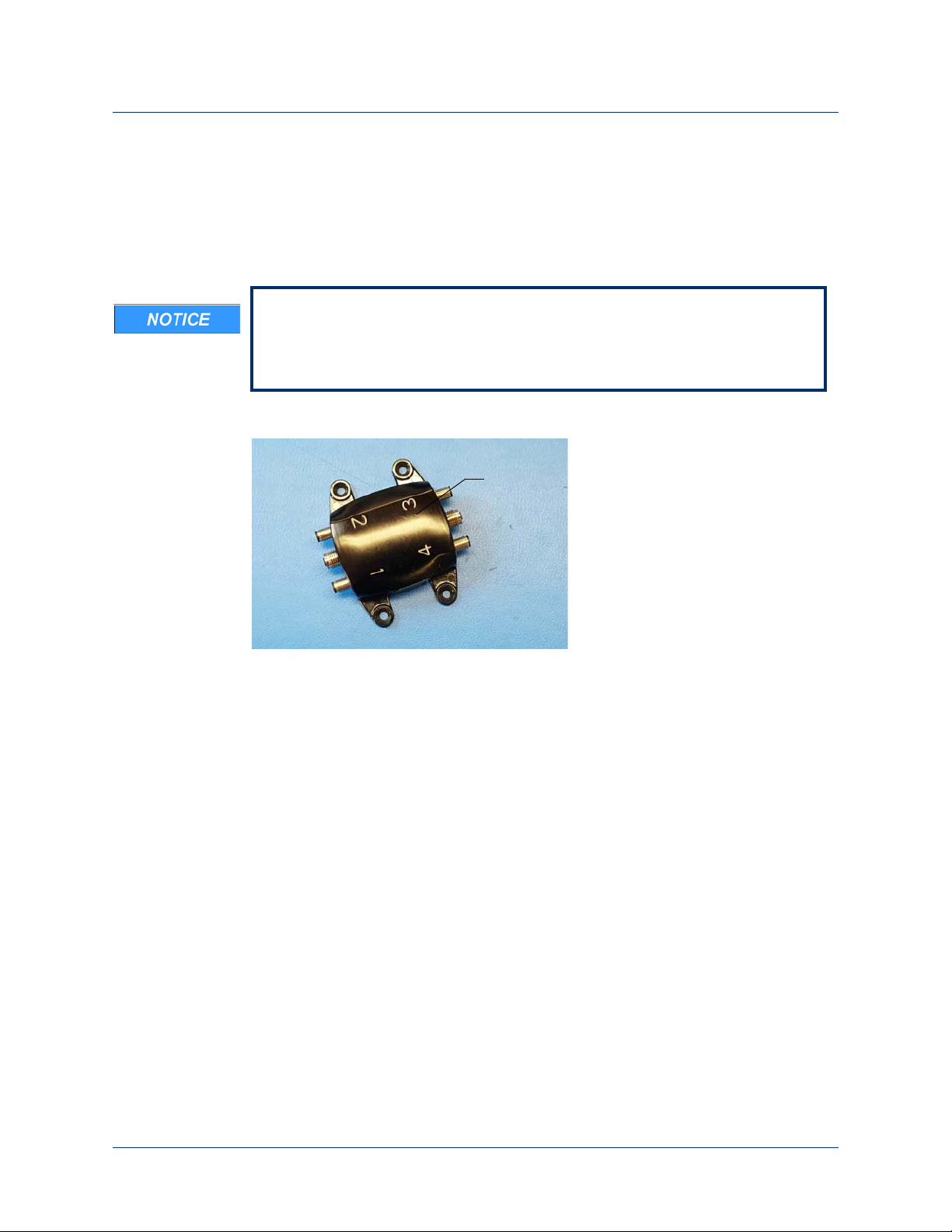
ACI (Arm Control Interface) Module
The ACI Module, see Figure 8, receives signals from user inputs (e.g., surface EMG
electrodes and pressure transducers) and sends them to the MAC which in turn
controls the arm. The ACI Module provides four user inputs and connects to the
arm.
The arm supports up to four IMU/ACI modules at a time in multiple
combinations, with a maximum of two IMUs. For example, your prosthetist
may configure the arm to support two IMU modules and two wired ACI
modules or four wired ACI modules and no IMUs.
Figure 8. ACI Module
26 Use or Disclosure of Data Contained on this Page is Subject to the Restrictions on the Inside Title Page of this Document -- Rev 1.8
Page 27
Input and Output Control Devices
Inertial
Measurement
Unit
Surface EMG
Electrodes
The arm uses several input devices and a single output device to control the arm.
The following sections describe these devices.
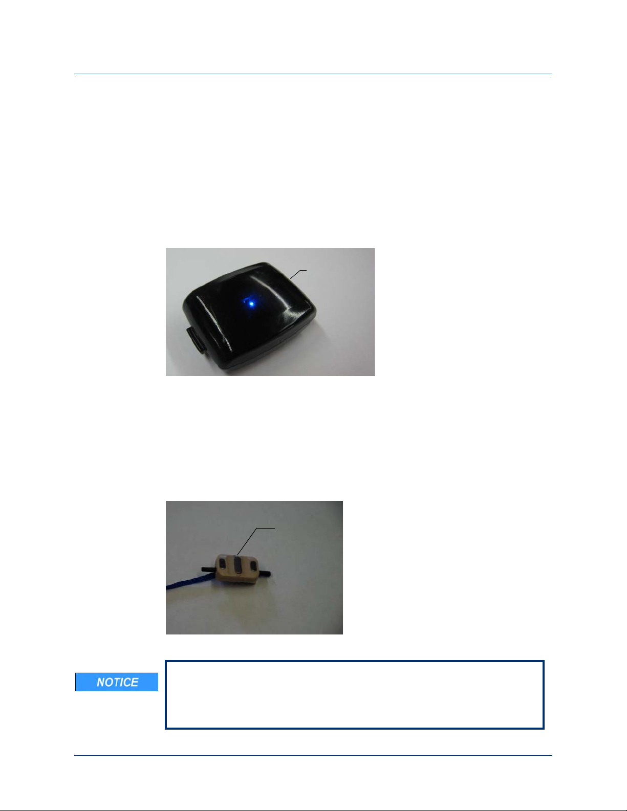
IMUs (Inertial Measurement Units)
IMUs are placed on top of your shoes and command motion or grip selection by
having you tilt your foot. See
Figure 9. Example Inertial Measurement Unit
Figure 9. To install the IMUs see Installing IMUs.
LUKE Arm System
EMG (Surface EMG Electrodes)
EMGs are placed on your skin or embedded into your socket to maintain contact
against your skin. EMGs are used to read electrical signals from underlying muscle
contractions. EMGs command motion by having you contract the selected muscle.
Figure 10 shows an example of a type of EMG.
Figure 10. Example EMG
When donning the arm system, static electricity discharge to EMGs can
damage them. To minimize the chance of EMG damage, touch any metal on
the arm before touching the EMGs. If you think the EMG is not working
correctly, see
Troubleshooting the Arm.
Rev 1.8 -- Use or Disclosure of Data Contained on this Page is Subject to the Restrictions on the Inside Title Page of this Document 12/5/1627
Page 28

IMU LED Status
The IMU LED shows the functions of the IMU. Pressing the display button for less
than one second causes the IMU battery to blink showing the charge level.
describes the functions of the IMU LEDs.
Table 8. IMU LED Status
User Controls and Wrist Display
Table 8
Function Color Status Description
Normal
Operation
Walk Detect Blue Solid Indicates walk detect mode.
Blue One blink every five (5)
seconds
IMUs are operating normally
and are communicating with
the arm.
For more information see
IMU - Walk Detect and
Zeroing the IMUs.
Fault Amber Blinking Indicates a sensor self-test
has failed. Try resetting the
IMU by removing it from the
charging pad, waiting five (5)
seconds, and then placing
the IMU on the charging
pad. If the condition
continues contact Technical
Support. See
Technical Support
Solid Indicates charging has been
paused. The system should
recover from this condition.
If after 30 minutes charging
does not continue, contact
Technical Support for service
on the charger or the IMU.
See
Contacting Technical
Support
Contacting
.
.
Rev 1.8 -- Use or Disclosure of Data Contained on this Page is Subject to the Restrictions on the Inside Title Page of this Document 12/5/1645
Page 29

Chapter 3: Arm Types and User Controls
Table 8. IMU LED Status
Function Color Status Description
Checking
Battery
Charge
Level or
Shaking to
Wake
Sleep Mode Off No blinks IMU is in sleep mode. See
Blue 5 blinks every 5 seconds
(3 times)
4 blinks every 5 seconds
(3 times)
3 blinks every 5 seconds
(3 times)
2 blinks every 5 seconds
(3 times)
1 blink every 5 seconds
(3 times)
Fully charged (80% to 100%)
Charge level is dropping
(60% to 80%)
Charge level is dropping
(40% to 60%)
Charge level is dropping
(20% to 40%)
Low battery (0% to 20%).
See
Charging the IMU
Battery
.
Waking a Sleeping IMU.
Discharged
Battery
Awake and
Waiting
Off No blinks IMU battery is discharged.
See
Charging the IMU
Battery
Off No blinks IMU is awake and waiting to
connect to the arm.
.
46 Use or Disclosure of Data Contained on this Page is Subject to the Restrictions on the Inside Title Page of this Document -- Rev 1.8
Page 30

Setting Up the Arm
This chapter provides information on how to set up the arm. Based on how your
prosthetist configured your arm, you may need to install some arm parts and then
don the arm to ensure proper fit prior to using the arm.
Topics in this chapter include:
Installing IMUs
•
• Donning (Putting On) the Arm
Before installing the arm parts and donning the arm be sure to visually inspect
all the arm parts and the arm for any sign of damage. If there is any sign of
damage, contact Technical Support. See
4
Contacting Technical Support.
Installing IMUs
If your arm’s control scheme calls for IMUs with shoe clips, you can install them at
this time. There are two steps to installing the IMU:
1. Attaching the IMU to the shoe clip.
2. Attaching the shoe clip to your shoe.
If you need help putting on and taking off the IMUs with shoe clips, have your
caregiver available at this time.
The IMUs have an IP57 rating. The IP rating specifies the strength of an
enclosure against solids (such as dust) and liquids. An IP57 rating provides
resistance to water at depths up to 1 m (39 inches) and resistance to fine dust.
Rev 1.8 -- Use or Disclosure of Data Contained on this Page is Subject to the Restrictions on the Inside Title Page of this Document r49
Page 31

Chapter 4: Setting Up the Arm
The IMUs will not provide data if dramatically tipped (close to vertical). Be sure
to position the IMU as close to level as possible when installing the IMU. If you
attach the IMU to your shoe at a severe angle to begin with, the IMU will not
provide the full range of motion after zeroing.
Installing the IMU to the Shoe Clip
To install the IMU to the shoe clip see Figure 21 and perform the following steps:
Be sure to install the IMU(s) onto the correct foot as configured by your
prosthetist. DO NOT SWAP THE IMU(s) DURING INSTALLATION.
1. Slide the tabbed end of the IMU into the open end of the shoe clip.
When installing the IMU onto the shoe clip, please ensure the following:
• The Front Arrow label on the bottom of the IMU is facing towards your
toes.
• Keep the IMU aligned with the direction of movement. This will prevent any
cross talk from occurring.
2. Press down on the IMU until the shoe clip retention tab snaps into the IMU slot.
Ensure the IMU is fastened securely to the shoe clip.
• The shoe clip can be put on the shoe either before or after the IMU is
installed on the shoe clip.
• You can attach the IMU to the shoe by alternate means (i.e., straps or
pockets) as long as it is securely attached.
50 Use or Disclosure of Data Contained on this Page is Subject to the Restrictions on the Inside Title Page of this Document -- Rev 1.8
Page 32

Figure 21. Attaching the IMU to the Shoe Clip
Open End
of Shoe Clip
IMU Tab
Press Down On IMU
IMU Tab
Open End
of Shoe Clip
Front
P
Part 1
Par t 2
Part 3
Front
Label
Installing IMUs
Rev 1.8 -- Use or Disclosure of Data Contained on this Page is Subject to the Restrictions on the Inside Title Page of this Document 12/5/1651
Page 33

Chapter 4: Setting Up the Arm
Open End of Shoe Clip
NOTE: IMU is shown attached
to shoe clip.
Installing the Shoe Clip to Your Shoe
To install the shoe clip to your shoe see Figure 22 and perform the following steps:
• Note that the shoe clip can be installed onto your shoe with the shoe off
your foot or on your foot.
• Once you have installed the shoe clip, the shoe clip can remain on the
shoe.
1. Orient the shoe clip so that the open end of the clip is facing towards your toes.
2. Slide the shoe clip under the laces of the shoe (left or right).
When installing the shoe clip to the shoe, please ensure the following:
• The shoe clip passes through at least two of the shoe’s laces to ensure the
clip is secure and stable.
• The Front Arrow label on the bottom of the IMU is facing towards your
toes.
3. Tighten the laces to secure the IMU and shoe clip to the shoe.
4. If you have not already done so put on the shoe.
5. Once you have installed the IMUs you can don (put on) the arm. See
(Putting On) the Arm
.
Figure 22. Attaching the Shoe Clip to the Shoe
Donning
52 Use or Disclosure of Data Contained on this Page is Subject to the Restrictions on the Inside Title Page of this Document -- Rev 1.8
Page 34

The IMUs do not contain an ON/OFF button. An IMU that is awake and set
up to communicate with an arm will do so once the arm is powered ON. See
Waking a Sleeping IMU and Initializing the Arm.
Location and Orientation of the IMUs
During the configuration process your prosthetist will have located and oriented the
IMUs to ensure proper operation of the arm. Be sure to locate and orient the IMUs
per your prosthetist’s instructions.
Waking a Sleeping IMU
When an IMU has not communicated with the arm for more than 30 minutes, the
IMU reverts to a sleep mode to conserve the battery. When in sleep mode the IMU
is not listening for arm communication.
Waking a Sleeping IMU
As a result, if the IMU is in sleep mode when the arm is turned on, it will not
connect with the arm. This results in the Grip Select LEDs sweeping while the arm
is trying to find the IMUs. If no IMUs are found, the System Fault Icons on the wrist
display blink along with an “IMU Comm Lost” fault code. Shaking your foot with
the IMU attached wakes the IMU from sleep mode so that the IMU is ready to
communicate with the arm once the arm system is powered up.
An IMU that has been shaken awake is waiting to communicate with the arm. IMUs
that are not actively communicating with an arm blink the battery state of charge
whenever they are shaken, regardless of whether they are sleeping or not.
If the IMU does not communicate with the arm within five (5) minutes of being
shaken awake, the IMU reverts back to sleep mode to conserve the battery.
Rev 1.8 -- Use or Disclosure of Data Contained on this Page is Subject to the Restrictions on the Inside Title Page of this Document 12/5/1653
Page 35

Chapter 5: Using the Arm
IMU - Walk Detect
The IMUs are designed to detect rapid foot movements (such as those seen while
walking) and not use these movements as arm commands. For example, if you
shake your feet the IMUs would detect this as motion other than a normal
command. When walk detect is active, the white Arm Mode LED blinks rapidly and
the blue IMU LED is solid. Note that when walk detect is active you will not be able
to move the arm using the IMUs, however, non-IMU controls will continue to
function as configured. If you are concerned about arm movement while walking (or
at other times) put the arm in Standby mode prior to walking.
When you stop walking and the IMUs come to rest, the arm reverts back to the
previous mode (Arm or Hand) the arm was in prior to entering walk detect and
resumes normal operation. This happens automatically when the IMU commands
return to zero. If the walk detect LED continues to blink, this indicates that the arm
is still receiving a command from one of your inputs. To resolve this issue, make
sure your IMUs are positioned correctly, your feet are flat/normal to the ground and
you are not activating any other inputs.
If you cannot resume normal operation of the arm and the white Arm Mode LED
continues blinking with your feet flat on the ground, the IMU zero point is incorrect
and the current signal level is above a set threshold. To fix this issue you need to
re-position the IMUs on your feet or zero the IMUs by going into Standby mode.
Zeroing the IMUs.
See
IMU - Angle Limit Detect
The IMUs are designed to detect when you exceed the IMUs’ angle limit. This
occurs when you tip the IMUs more than 45 degrees since the last time the IMUs
were zeroed or were out of range. As a result, the white Arm Mode LED on the
Wrist Display blinks rapidly informing you of the problem.
If the IMUs exceed 45 degrees, you will not be able to move the arm with the IMUs,
however, non-IMU controls will continue to function as designed. To resume normal
operation you need to return your foot/feet to the rest or zero position.
If the white Arm Mode LED continues to blink, you need to reposition the IMUs,
re-position your feet, or zero the IMUs by going into Standby mode. See
the IMUs
.
Zeroing
58 Use or Disclosure of Data Contained on this Page is Subject to the Restrictions on the Inside Title Page of this Document -- Rev 1.8
Page 36

Mode Change Interlock
If you are in the process of switching modes (Standby to Hand mode or Hand to
Arm mode) and the system detects a command to move, the mode change
interlock becomes active. As a result, the white Arm Mode LED on the Wrist
Display blinks rapidly informing you of the problem.
You can switch modes when mode change interlock is active, however you will not
be able to command the arm. When the IMUs are returned to the zero position or
the wired input falls below the activation threshold you will be able to command the
arm.
If the problem does not clear automatically and the white Arm Mode LED continues
to blink, you need to re-position the IMUs/feet or zero the IMUs by going into
Standby mode (See
not activated.
Zeroing the IMUs
Zeroing the IMUs establishes a neutral position. When you take the arm out of
Standby mode the system zeros the IMUs by taking a snapshot of the IMU’s
position and identifies that position as neutral. For example, if you should take the
arm out of Standby mode while your feet and attached IMUs are in an inclined
position the IMUs will be zeroed at that position. If you should then place your feet
and IMUs in a different position without zeroing the IMUs the result could be
unintended arm motion. To ensure this does not occur re-zero the IMU s by
performing the following steps:
1. Using the designated mode input place the arm in the Standby mode.
2. Place your feet at the position you want to zero the IMUs (usually feet flat on the
ground).
Key Concepts
Zeroing the IMUs) or you need to ensure the wired inputs are
3. Using the designated mode input take the arm out of Standby mode.
4. The IMUs are now zeroed for that position and the IMU LED blinks blue once
every five (5) seconds.
If you have to continually re-zero the IMUs while not changing the neutral
position you should check to ensure the IMUs and shoe clips are securely
attached to your shoes.
Rev 1.8 -- Use or Disclosure of Data Contained on this Page is Subject to the Restrictions on the Inside Title Page of this Document 12/5/1659
Page 37

Chapter 6: Charging the Batteries
Power Cord
Charging Pad
IMUs
Charging Pad
Status LEDs
Charging the IMU Battery
To charge the IMU battery you need to remove the IMU from its shoe mounting clip
and place the IMU on the charging pad. Note the following when charging the IMU
battery:
• IMUs cannot be charged during use. The prosthesis stops functioning
and the System Fault Icon on the wrist display illuminates if this is
attempted.
• Do not place any objects on the charging pad other than the IMUs.
• Mobius Bionics suggests that you charge the IMU battery overnight.
• The estimated time to recharge an empty IMU battery to 80% capacity is
less than 2.0 hours.
• You can charge up to two IMUs at a time on the charging pad.
Figure 43 to see how the IMU is placed on the charging pad and Table 17 for a
See
description of the IMU charging status LEDs.
Figure 43. Charging the IMU Battery
90 Use or Disclosure of Data Contained on this Page is Subject to the Restrictions on the Inside Title Page of this Document -- Rev 1.8
Page 38

Charging the IMU Battery
Table 17. IMU Battery Charging LED Status
Function Color Status Description
Charging Blue Slow Blinking IMU is performing a self-test.
Fast Blinking Battery is charging.
NOTE: A fully discharged
IMU may need to partially
charge before the LED will
blink blue. When the IMU is
on the charging pad, the
charging pad’s status LEDs
will be blue.
Solid Battery is fully charged.
Fault Amber Blinking Indicates a sensor self-test
has failed. Try resetting the
IMU by removing it from the
charging pad, waiting five (5)
seconds, and then placing
the IMU on the charging
pad. If condition continues
contact Technical Support.
See
Contacting Technical
Support
.
Amber Solid Indicates charging has been
paused. The system should
recover from this condition.
If after 30 minutes charging
does not continue, contact
Technical Support for service
on the charger or the IMU.
See
Contacting Technical
Support
.
To charge the IMU battery perform the following steps:
1. Turn OFF the arm.
2. Plug the charging pad’s AC Adapter into an electrical outlet.
3. Remove the IMU from its shoe mounting clip.
4. Set the IMU on the charging pad circle. (One IMU per circle).
Ensure the IMU is placed on the pad with the LED facing up, so you can view
the IMU LEDs.
Rev 1.8 -- Use or Disclosure of Data Contained on this Page is Subject to the Restrictions on the Inside Title Page of this Document 12/5/1691
Page 39

Chapter 6: Charging the Batteries
5. Ensure the charging pad status LEDs are ON when charging the IMUs. See
Figure 43.
6. View the status of the IMU battery charge status LEDs. See
Table 17.
7. Reattach the IMU to its shoe clip. The IMU is now ready for use.
You cannot replace the IMU battery. If there is a problem with the IMU
battery, turn the arm power OFF, doff the arm, and contact Technical
Support. See
Contacting Technical Support.
IMUs are awake and waiting for communication from the arm once it is
removed from the charging pad. However, the IMU goes into sleep mode if it
has not communicated with the arm within 30 minutes. See
Sleeping IMU
.
Waking a
92 Use or Disclosure of Data Contained on this Page is Subject to the Restrictions on the Inside Title Page of this Document -- Rev 1.8
Page 40

Chapter 7: Maintaining and Troubleshooting the Arm
Troubleshooting the Arm
This section provides basic troubleshooting steps to help you find and resolve
possible problems that may occur with the arm. It also describes how alerts are
generated and indicated to identify possible problems.
If at any time you feel the arm is not in proper working order (e.g., slow to
move, hard to control, making odd sounds, etc.) turn the battery power OFF
and contact Technical Support at once. See
LUKE Arm System Alerts
The arm system generates alerts to indicate possible problems. Many of these alerts
are indicated by LEDs. The LED may blink or turn a certain color to indicate the
alert. The arm system may also sound a tone to indicate an alert.
All alerts are low priority alarms and technical alarms.
Contacting Technical Support.
Alerts may be generated when:
• A battery is discharged
• Hardware is damaged
Alerts are generated when:
• Communication with an IMU is lost
• You attempt to charge an IMU when the prosthesis is in operation
To learn more about these alerts see
Chapter 6, “Charging the Batteries”.
User Controls and Wrist Display and
100 Use or Disclosure of Data Contained on this Page is Subject to the Restrictions on the Inside Title Page of this Document -- Rev 1.8
Page 41

Troubleshooting
The following tables provide solutions to solving problems with the arm.
Table 18. Troubleshooting - Try This First
TRY
THIS
FIRST
Troubleshooting the Arm
These basic tips may help you quickly solve problems with the arm:
1. Put the arm into Standby Mode.
2. Check and secure the IMUs on your feet.
3. Take the arm out of Standby Mode.
1. Power the arm off.
2. Shake the IMUs to wake them. Look for the blinking blue
LEDs.
3. Make sure all cables are securely connected.
4. Put your feet flat on the ground
5. Power the arm on.
See the tables below to help you in troubleshooting problems with the arm system:
•
Table 19, Troubleshooting - Wrist Display and System Faults
– Use this table for help when Wrist Display LEDs are on or flashing
•
Table 20, Troubleshooting - Arm Function
– Use this table for help with moving the arm or changing grips
•
Table 21, Troubleshooting - Power and Battery Charging
– Use this table for help with powering the arm on and charging batteries
If the solutions in these troubleshooting tables do not solve the problem with the
arm, contact Technical Support. See
Contacting Technical Support.
Rev 1.8 -- Use or Disclosure of Data Contained on this Page is Subject to the Restrictions on the Inside Title Page of this Document
12/5/16101
Page 42

Chapter 7: Maintaining and Troubleshooting the Arm
Table 19. Troubleshooting - Wrist Display and System Faults
Problem Cause Solution
System Fault Icons Blinking
Fault Code: 3
System Fault Icons Blinking
Fault Code: 36
IMU not awake
IMU battery low
Ham radios, walkie
talkies, theft detectors, or
metal detectors are
affecting the arm
ACI not talking to arm
1. Power the arm off
2. Shake the IMUs to wake them
3. Power the arm on
1. Power the arm off
2. Shake the IMU to check the IMU
battery charge level and charge if
necessary
3. Power the arm on
1. Power the arm off
2. Move the arm at least 0.5 m (20 inches)
away from any ham radios, walkie
talkies, theft detectors, or metal
detectors
3. Power the arm on
1. Power the arm off
2. Check and tighten all system cables
3. Power the arm on
System Fault Icons Blinking
Fault Codes: 25, 26, 34,
256
System Fault Icons Blinking
Fault Code Not Listed
Arm motors warm
1. Power the arm off
2. Move to a cooler location if possible
3. Wait 15 minutes
4. Power the arm on
Contact Technical Support. See
Contacting Technical Support.
102 Use or Disclosure of Data Contained on this Page is Subject to the Restrictions on the Inside Title Page of this Document -- Rev 1.8
Page 43

Troubleshooting the Arm
Sweeping
Table 19. Troubleshooting - Wrist Display and System Faults
Problem Cause Solution
Low Battery Icon On Battery is low Replace the external battery in the holster
with a fully charged battery.
Plug the AC Adapter into the forearm
charging port
External battery not
connected
1. Check that the external battery is properly seated in the holster
2. Check and tighten the cables between
the arm and the holster
Grip Select LEDs Sweeping IMU not talking to arm Shake the IMUs to wake them
IMU battery is low Charge the IMUs
Ham radios, walkie
talkies, theft detectors, or
metal detectors are
Move the arm at least 0.5 m (20 inches)
away from any ham radios, walkie talkies,
theft detectors, or metal detectors
affecting the arm
Arm Mode LED Blinking Walk Detect
1. Stop walking
2. Put your feet flat on the ground
3. Check that the Arm Mode LED has
stopped blinking
IMU tilted too far
1. Put the arm into Standby Mode
2. Check and secure the IMUs on your
feet
3. Put your feet flat on the ground
4. Take the arm out of Standby Mode
Input device not working Contact Technical Support. See
Contacting Technical Support.
Rev 1.8 -- Use or Disclosure of Data Contained on this Page is Subject to the Restrictions on the Inside Title Page of this Document
12/5/16103
Page 44

Chapter 7: Maintaining and Troubleshooting the Arm
Table 20. Troubleshooting - Arm Function
Problem Cause Solution
Arm moving without
command
Arm not moving
IMU zero position
changed
Sweat near EMGs
Ham radios or walkie
talkies are affecting the
arm
Arm is in Standby Mode Put the arm into Hand Mode
Arm is off
Arm is faulted
1. Put the arm into Standby Mode
2. Check and secure the IMUs on your
feet.
3. Put your feet flat on the ground
4. Take the arm out of Standby Mode
1. Put the arm into Standby Mode
2. Wipe the sweat from the EMG
electrode and skin with a dry cloth
3. Take the arm out of Standby Mode
1. Put the arm into Standby Mode
2. Move the arm at least 0.5 m (20 inches)
away from any ham radios or walkie
talkies
3. Take the arm out of Standby Mode
1. Shake the IMUs to wake them
2. Power the arm on
See
Table 19, Troubleshooting - Wrist
Display and System Faults
.
Input device not
connected
Cannot change Modes Input device not
connected
Input device not working Contact Technical Support. See
Cannot change grips Hand is not fully open
Input device not working Contact Technical Support. See
1. Power the arm off
2. Check and tighten all connections at the
ACI
3. Power the arm on
1. Power the arm off
2. Check and tighten all connections at the
ACI
3. Power the arm on
Contacting Technical Support.
1. Put the arm into Hand Mode
2. Fully open the hand
3. Change grips
Contacting Technical Support.
104 Use or Disclosure of Data Contained on this Page is Subject to the Restrictions on the Inside Title Page of this Document -- Rev 1.8
Page 45

Table 21. Troubleshooting - Power and Battery Charging
Problem Cause Solution
Troubleshooting the Arm
Arm does not power on Internal battery too low
External battery too low
External battery not
connected
Internal Battery Charging
Charging Status Icon Blinking
Ye l l ow
Internal battery charging
paused
1. Plug the AC Adapter into the forearm
charging port
2. The charging status icon first blinks
yellow for a few minutes. Wait until the
charging status icon blinks blue.
3. Power the arm on
1. Replace the external battery in the hol-
ster with a fully charged one
2. Power the arm on
1. Check that the external battery is prop-
erly seated in the holster
2. Check and tighten the cables between
the arm and the holster
3. Power the arm on
1. Move the arm to a cooler location
2. Wait up to 2 hours. You can keep the
arm on and the AC adapter connected
while waiting.
3. Charging should continue on its own. If
it does not, contact Technical Support.
See
Contacting Technical Support.
Charging Status Icon On
Solid Yellow
Rev 1.8 -- Use or Disclosure of Data Contained on this Page is Subject to the Restrictions on the Inside Title Page of this Document
Internal battery charging
fault
Contact Technical Support. See
Contacting Technical Support.
12/5/16105
Page 46

Chapter 7: Maintaining and Troubleshooting the Arm
Table 21. Troubleshooting - Power and Battery Charging
Problem Cause Solution
External Battery Charging
Charging Dock Fault Status
Blinking Yellow
Charging Dock Fault Status
On Solid Yellow
IMU Charging
IMU Yellow LED On Solid Charging paused
IMU Yellow LED Blinking Self test failure
Charging paused
Charging fault Contact Technical Support. See
1. Wait up to 2 hours. You can keep the
charging dock on and the battery in the
charging dock while waiting.
2. Charging should continue on its own. If
it does not, contact Technical Support.
See
Contacting Technical Support.
Contacting Technical Support.
1. Wait up to 30 minutes. You can keep
the charging pad on and the IMU on the
charging pad while waiting.
2. Charging should continue on its own. If
it does not, contact Technical Support.
See
Contacting Technical Support.
1. Remove the IMU from the charging pad
2. Wait 5 seconds
3. Place the IMU on the charging pad
4. If the error persists, contact Technical
Support. See
Support
Contacting Technical
.
IMU LED off IMU not talking to
charging pad
1. Clean the top of the charging pad.
2. Clean the bottom of the IMU.
3. Place the IMU, LED side up, on the
charging pad’s center circle.
If the solutions in these troubleshooting tables do not solve the problem with the
arm, contact Technical Support. See
106 Use or Disclosure of Data Contained on this Page is Subject to the Restrictions on the Inside Title Page of this Document -- Rev 1.8
Contacting Technical Support.
Page 47

Technical Specifications
This appendix provides technical specifications for the LUKE arm, battery, AC
Adapter and charging pad.
Arm Specifications
:
Table 22. Arm System Specifications
Parameter Range/Explanation
Compliance The LUKE arm system complies with IEC 60601-1:2005
Power Type The arm is internally powered when under battery power
Designation The arm is designated Class II when plugged into the AC Adapter
A
Parts Type The arm and all body worn accessories are Type BF applied parts
:
Table 23. Operating Environmental Range
Parameter Range/Explanation
Operating Temperature
Humidity 15% to 93% (non-condensing)
Pressure 700 hPa to 1060 hPa
Arm and body worn Mobius
Bionics supplied accessories IP
rating
Rev 1.8 -- Use or Disclosure of Data Contained on this Page is Subject to the Restrictions on the Inside Title Page of this Document 107
• 10 °C to 40 °C (50 °F to 104 °F) with no degradation in
performance
• -10 °C to 50 °C (14 °F to 122 °F) with reduced arm speed
and/or load capacity
IP52
Page 48

Appendix A: Technical Specifications
Table 23. Operating Environmental Range (Continued)
Parameter Range/Explanation
IMU IP Rating IP57
When using the arm continuously in a hot environment (40°C, 104°F) and
while charging the internal battery, portions of the forearm and upper arm (if
applicable) could reach temperatures of 54°C - 57°C (130°F - 135°F), when
evaluated as directed in IEC60601-1: 2005-12.
:
Table 24. Transport and Storage Environmental Range
Parameter Range
Storage Temperature (excluding
-25 °C to 70 °C (-13 °F to 158 °F)
battery)
Humidity 15% to 93% (non-condensing)
Pressure 700 hPa to 1060 hPa
:
Table 25. Service Life Specifications
Part Service Life
Arm Expected to function for up to three (3) years with an 18 month
service interval
Internal and External Batteries Expected to provide at least 80% of new capacity for up to a year of
typical use
IMU Battery Expected runtime is at least 18 hours for up to a year of use
AC Adapter and Charging Pad Expected to function for up to three (3) years
External Battery Holster and
Expected to function for up to three (3) years
External Battery Charging Dock
ACI and Cables Expected to function for up to three (3) years
108 Use or Disclosure of Data Contained on this Page is Subject to the Restrictions on the Inside Title Page of this Document -- Rev 1.8
Page 49

:
Table 26. Mass of Arm Configurations
Arm Configuration Mass
Arm Specifications
Shoulder Configuration (SC)
4.7 kg
Humeral Configuration (HC) 3.4 kg
Radial Configuration (RC) 1.4 kg
:
Table 27. Dimensions of Arm Configurations
Arm Configuration Dimensions
Shoulder Configuration (SC) See Figure 48
Humeral Configuration (HC) See Figure 49
Radial Configuration (RC) See Figure 50
Rev 1.8 -- Use or Disclosure of Data Contained on this Page is Subject to the Restrictions on the Inside Title Page of this Document 12/5/16109
Page 50

Appendix A: Technical Specifications
23.2323
23aa
23
4.3
26.4
23.4
26.4
9.8
38.6
14.5
19.5
See Note 1
See Note 2
Figure 48. Dimensions of Shoulder Configuration (In Centimeters)
• NOTE 1: Upper arm length configurations in 1 cm increments from 26.4 to
31.4 cm. See
Arm Types.
• NOTE 2: Forearm length configurations in 1 cm increments from 23.4 cm to
27.4 cm. See
Arm Types
110 Use or Disclosure of Data Contained on this Page is Subject to the Restrictions on the Inside Title Page of this Document -- Rev 1.8
Page 51

Arm Specifications
14.5
19.5
23.4
12.7
17.3
See Note 3
12.1
14.5
31.6
Figure 49. Dimensions of Humeral Configuration (In Centimeters)
• NOTE 3: Forearm length configurations in 1 cm increments from 23.4 cm to
27.4 cm. See
Arm Types.
Figure 50. Dimensions of Radial Configuration (In Centimeters)
Rev 1.8 -- Use or Disclosure of Data Contained on this Page is Subject to the Restrictions on the Inside Title Page of this Document 12/5/16111
Page 52

Appendix A: Technical Specifications
Battery Specifications
:
Table 28. Battery Charge and Operation Times
Arm System
Configuration
Battery Type One (1) Hour Charge
Operation Time
1
Full Charge2
Operation Time
1
SC/HC Internal Battery One (1) Hour Two (2) Hours
SC/HC External Battery Two (2) Hours
RC External Battery Four (4) Hours
IMU
Not Applicable Not Applicable
Five (5) Hours
Ten (10) Hours
One (1) Day
NOTES:
1. Actual use time may vary from stated figures based on use patterns, battery age, and arm configuration.
Contact Technical Support for additional information. See
2. See
Chapter 6, “Charging the Batteries” for charging time.
:
Contacting Technical Support.
Table 29. Power Specifications - Internal Battery
Parameter Range/Explanation
Battery Type Lithium-Ion
Capacity 30 Watt-Hours
Charging time (approximate) 80% capacity in less than 2.0 hours
Storage Life Three (3) months without recharging
Storage Temperature Short Term (24 Hours Maximum): -25°C to 70°C (-13°F to 158°F)
Long Term: -10°C to 50°C (14°F to 122°F)
:
Table 30. Power Specifications - External Battery
Parameter Range/Explanation
Battery Type Lithium-Ion
Capacity 74 Watt-Hours
Charging time (approximate) 80% capacity in less than 2.0 hours
Storage Life Three (3) months without recharging
112 Use or Disclosure of Data Contained on this Page is Subject to the Restrictions on the Inside Title Page of this Document -- Rev 1.8
Page 53

AC Adapter Specifications
Table 30. Power Specifications - External Battery (Continued)
Parameter Range/Explanation
Storage Temperature Short Term (24 Hours Maximum): -25 °C to 70 °C (-13 °F to
158 °F)
Long Term: -10 °C to 50 °C (14 °F to 122 °F)
:
Table 31. Power Specifications - IMU Battery
Parameter Range/Explanation
Battery Type Lithium-Polymer
Capacity 190 mAh
Charging time (approximation) 80% capacity in less than two (2.0) hours
Storage Life Three (3) months without recharging
Storage Temperature Short Term (24 Hours Maximum): -25 °C to 70 °C (-13 °F to
158 °F)
Long Term: -10 °C to 50 °C (14 °F to 122 °F)
AC Adapter Specifications
:
Table 32. AC Adapter Specifications
Parameter Range/Explanation
Input Voltage 100 VAC - 240 VAC
Input Frequency 50/60 Hz
Input Current 1.5 Amps
Operating Temperature 0 °C to +70 °C (32 °F to 158 °F)
Operating Humidity 10% to 95% RH, non-condensing
Storage Temperature -40 °C to +80 °C (-40 °F to 176 °F)
Rev 1.8 -- Use or Disclosure of Data Contained on this Page is Subject to the Restrictions on the Inside Title Page of this Document 12/5/16113
Page 54

Appendix A: Technical Specifications
Charging Pad Specifications
:
Table 33. Charging Pad Specifications
Parameter Range/Explanation
Input Voltage 100 VAC - 240 VAC
Input Frequency 50/60 Hz
Current Rating 1 Amp Maximum
Transmit Frequency Range 100 kHz - 205 kHz
Transm i t P ower <5 W
Protocol Qi version 1.1, Wireless Power Consortium
Effective Range 10 mm or less
Wireless Security Qi version 1.1
Quality of Service Provisions Any debris or clutter between the bottom of the IMU and the
Charging Pad may prevent IMU charging. Any increase in the
distance between the IMU and Charging Pad will increase
communication interference. This interference, however, will not
cause any incorrect data to be sent and will not cause any harm to
the LUKE arm system.
Loss or corruption of data between the IMU and Charging Pad for
more than 2 seconds can result in the interruption of charging.
In these cases, communication problems can usually be resolved by
ensuring the top of the Charging Pad is clean and clear of clutter,
the IMU is clean and its label is free of wrinkles, and that IMUs are
placed label side down and placed as close as possible to the center
of the charging pad targets.
114 Use or Disclosure of Data Contained on this Page is Subject to the Restrictions on the Inside Title Page of this Document -- Rev 1.8
Page 55

Arm Radio Specifications
:
Table 34. Arm Radio Specifications
Parameter Range/Explanation
Arm Radio Specifications
Transmit and Receive Frequency
Range
Effective Radiated Power <10 mW
Modulation Direct Sequence Spread Spectrum per IEEE 802.15.4-2006
Protocol Proprietary Frequency Hopping Communication Protocol
FCC Compliance This device complies with part 15 of the FCC Rules. Operation is
Effective Range (Arm/IMU) 3 m or less
Effective Range (Arm/Dongle) 1 m or less
Wireless Security Proprietary Frequency Hopping Communication Protocol
2.4 - 2.5 GHz
subject to the following two conditions: (1) This device may not
cause harmful interference, and (2) this device must accept any
interference received, including interference that may cause
undesired operation.
Pursuant to FCC 15.21 of the FCC rules, changes not expressly
approved by Mobius Bionics might cause harmful interference and
void the FCC authorization to operate this product.
This product complies with FCC OET Bulletin 65 radiation
exposure limits set forth for an uncontrolled environment.
Rev 1.8 -- Use or Disclosure of Data Contained on this Page is Subject to the Restrictions on the Inside Title Page of this Document 12/5/16115
Page 56

Appendix A: Technical Specifications
Table 34. Arm Radio Specifications (Continued)
Parameter Range/Explanation
Quality of Service Provisions Interruption or corruption of communication between the Arm and
IMUs can lead to interruptions in arm motion. Interruption of
communication for more than 2 seconds may lead to the system
reverting to Standby mode. Interruption of communication for more
than 8 seconds results in the system declaring a fault.
Common consumer electronic devices that transmit in the same
frequency band used by the LUKE arm system may prevent the
Arm and IMUs from communicating. Microwave ovens, Bluetooth®
devices, Wi-Fi® networks and 2.4 GHz cordless phones, when
transmitting or receiving, can cause interruption of communication
between the Arm and IMUs. During testing, the LUKE arm system
experienced occasional communication interruptions in the
presence of Bluetooth mice. It is likely that other devices operating
in similar frequency ranges can have a similar effect. This
interference, however, will not cause any incorrect data to be sent
and will not cause any harm to the LUKE arm system.
Some metal detectors and anti-theft detection systems at store exits
transmit in the same frequency band used by the LUKE arm system.
These devices can cause interruption of communication between
the Arm and IMUs. Again, this interference will not cause any
incorrect data to be sent and will not cause any harm to the LUKE
arm system.
In each of these cases, communication problems can usually be
resolved by turning off or moving away from other RF transmitting
devices.
116 Use or Disclosure of Data Contained on this Page is Subject to the Restrictions on the Inside Title Page of this Document -- Rev 1.8
Page 57

Guidance and Manufacturer’s Declaration
This Appendix details information on the electromagnetic environment and
recommended spacing between portable and mobile RF communications
equipment (transmitters) and the LUKE arm system.
Electromagnetic Environment
The LUKE arm system is intended for use in the electromagnetic environment
specified in
assure that it is used in such an environment.
Electromagnetic Emissions
Table 35 and Table 36. The user of the LUKE arm system should
B
Table 35. Guidance and Manufacturer’s Declaration - Electromagnetic Emissions
Emissions Test Compliance Electromagnetic Environment - Guidance
RF emissions
CISPR 11
RF emissions
CISPR 11
Rev. 1.8 -- Use or Disclosure of Data Contained on this Page is Subject to the Copyright Restrictions on the Inside Title Page of this Document 117
Group 1 The LUKE arm system uses RF energy only for its
internal function. Therefore, its RF emissions are very
low and are not likely to cause any interference in
nearby electronic equipment.
Class B The LUKE arm system is suitable for use in all
establishments, including domestic establishments and
those directly connected to the public low voltage
power supply network that supplies buildings used for
domestic purposes.
Page 58

Appendix B: Guidance and Manufacturer’s Declaration
Electromagnetic Immunity
Table 36. Guidance and Manufacturer’s Declaration - Electromagnetic Immunity
Immunity Test IEC 60601 Test
Level
Electrostatic
discharge (ESD)
+/- 6 kV contact
+/- 8 kV air
IEC 61000-4-2
Electrical fast
transient/burst
IEC 61000-4-4
+/- 2 kV for power
supply lines
+/- 1 kV for
input/output
lines
Surge
IEC 61000-4-5
+/- 1 kV line(s) to
line(s)
+/- 2 kV line(s) to
earth
Voltage dips, short
interruptions and
voltage variations
on power supply
input lines
IEC 61000-4-11
<5% U
T
(>95% dip in UT)
for 0,5 cycle
40% U
T
(60% dip in UT)
for 5 cycles
70% U
T
(30% dip in UT)
for 25 cycles
<5% U
T
(>95% dip in UT)
for 5 s
Compliance Level Electromagnetic
Environment - Guidance
+/- 6 kV contact
+/- 8 kV air
Floors should be wood,
concrete or ceramic tile. If
floors are covered with
synthetic material, the relative
humidity should be at least
30%.
+/- 2 kV for power
supply lines
+/- 1 kV for
Mains power quality should be
that of a typical commercial or
hospital environment.
input/output
lines
+/- 1 kV line(s) to
line(s)
+/- 2 kV line(s) to earth
<5% U
T
(>95% dip in UT)
for 0,5 cycle
40% U
T
(60% dip in UT)
for 5 cycles
70% U
T
(30% dip in UT)
for 25 cycles
<5% U
T
Mains power quality should be
that of a typical commercial or
hospital environment.
Mains power quality should be
that of a typical commercial or
hospital environment. If the
user of the LUKE arm system
requires continued operation
during power mains
interruptions, it is
recommended that the LUKE
arm system be powered from
an uninterruptible power
supply or a battery.
(>95% dip in UT)
for 5 s
Power frequency
(50/60 Hz)
magnetic field
IEC 61000-4-8
3 A/m 3 A/m Power frequency magnetic
fields should be at levels
characteristic of a typical
location in a typical
commercial or hospital
environment.
NOTE: U
is the a.c. mains voltage prior to application of the test level.
T
118 Use or Disclosure of Data Contained on this Page is Subject to the Copyright Restrictions on the Inside Title Page of this Document -- Rev. 1.8
Page 59

Electromagnetic Environment
d1.2P=
d0.35P=
d1.2P=
d0.35P=
d1.2P=
d0.18P=
d0.35P=
Table 36. Guidance and Manufacturer’s Declaration - Electromagnetic Immunity
Immunity Test IEC 60601 Test
Level
Conducted RF
IEC 61000-4-6
Radiated RF
IEC 61000-4-3
3 Vrms
150 kHz to 80 MHz
3 V/m
80 MHz to 2.5 GHz
(continued on next
page)
Compliance Level Electromagnetic
Environment - Guidance
Portable and mobile RF
communications equipment
should be used no closer to
any part of the LUKE arm
system, including cables, than
the recommended separation
distance calculated from the
equation applicable to the
frequency of the transmitter.
Recommended Separation
Distance:
3 Vrms
150 kHz to 80 MHz
10 V/m
26 MHz to 80 MHz
3 V/m
80 MHz to 460 MHz
10 V/m
460 MHz to 470 MHz
3 V/m
470 MHz to 690 MHz
20 V/m
690 MHz to 800MHz
20 V/m
800MHz to 965 MHz
(continued on next page)
where P is the maximum
output power rating of the
transmitter in watts (W)
according to the transmitter
manufacturer and d is the
recommended separation
distance in meters (m).
Rev. 1.8 -- Use or Disclosure of Data Contained on this Page is Subject to the Copyright Restrictions on the Inside Title Page of this Document 119
Page 60

Appendix B: Guidance and Manufacturer’s Declaration
d2.3P=
d0.35P=
Table 36. Guidance and Manufacturer’s Declaration - Electromagnetic Immunity
Immunity Test IEC 60601 Test
Level
Radiated RF
IEC 61000-4-3
3 V/m
80 MHz to 2.5 GHz
(continued)
Compliance Level Electromagnetic
Environment - Guidance
3 V/m
965MHz to 1.39 GHz
20 V/m
1.39 GHz to 6.0 GHz
Field strengths from fixed RF
transmitters, as determined by
an electromagnetic site survey
should be less than the
compliance level in each
frequency range.
b
Interference may occur in the
vicinity of equipment marked
with the following symbol:
a
Magnetic Fields
generated by:
N/A 0.1 kHz - 3.5 kHz
300 A/m
No special precautions
required.
• Metal Detectors
10 kHz - 60 kHz
• EAS Systems
50 A/m
and Tag
Deactivators
(No Standard
Applied)
50 kHz - 150 kHz
30 A/m
NOTE 1: At 80 MHz, 460 MHz, 470 MHz, 690 MHz, 800 MHz, 965 MHz, and 1.39 GHz, the higher
frequency range applies.
NOTE 2: These guidelines may not apply in all situations. Electromagnetic propagation is affected by
absorption and reflection from structures, objects and people.
a Field strengths from fixed transmitters, such as base stations for radio (cellular/cordless) telephones and
land mobile radios, amateur radio, AM and FM radio broadcast and TV broadcast cannot be predicted
theoretically with accuracy. To assess the electromagnetic environment due to fixed RF transmitters, an
electromagnetic site survey should be considered. If the measured field strength in the location in which
the LUKE arm system is used exceeds the applicable RF compliance level above, the LUKE arm system
should be observed to verify normal operation. If abnormal performance is observed, additional
measures may be necessary, such as re-orienting or relocating the LUKE arm system.
b Over the frequency range 150 kHz to 80 MHz, field strengths should be less than 3 V/m.
120 Use or Disclosure of Data Contained on this Page is Subject to the Copyright Restrictions on the Inside Title Page of this Document -- Rev. 1.8
Page 61

Recommended Separation Distances
d1.2P=
d0.35P=
d1.2P=
d0.35P=
d1.2P=
Recommended Separation Distances
The LUKE arm system is intended for use in an electromagnetic environment in
which radiated RF disturbances are controlled. The user of the LUKE arm system
can help prevent electromagnetic interference by maintaining a minimum distance
between portable and mobile RF communications equipment (transmitters) and the
LUKE arm system as recommended below, according to the maximum output
power of the communications equipment.
Table 37 and Table 38 defines the recommended separation distances between
portable and mobile RF communications equipment and the LUKE arm system.
Table 37. Recommended Separation Distances (Part I)
Rated Maximum Output
Power of Transmitter
W
0.01 0.12 0.035 0.12 0.035 0.12
0.1 0.37 0.11 0.37 0.11 0.37
1 1.2 0.35 1.2 0.35 1.2
10 3.7 1.1 3.7 1.1 3.7
100 12 3.5 12 3.5 12
For transmitters rated at a maximum output power not listed above, the recommended separation distance
d in meters (m) can be estimated using the equation applicable to the frequency of the transmitter, where P
is the maximum output power rating of the transmitter in watts (W) according to the transmitter
manufacturer.
NOTE 1: At 80 MHz, 460 MHz, 470 MHz, 690 MHz, 800 MHz, 965 MHz, and 1.39 GHz, the
separation distance for the higher frequency range applies.
NOTE 2: These guidelines may not apply in all situations. Electromagnetic propagation is affected by
absorption and reflection from structures, objects and people.
Separation Distance According to Frequency of Transmitter
m
150 kHz -
80 MHz
26 MHz -
80 MHz
80 MHz 460 MHz
460 MHz -
470 MHz
470 MHz -
690 MHz
Rev. 1.8 -- Use or Disclosure of Data Contained on this Page is Subject to the Copyright Restrictions on the Inside Title Page of this Document 121
Page 62

Appendix B: Guidance and Manufacturer’s Declaration
d0.18P=
d0.35P=
d2.3P=
d0.35P=
Table 38. Recommended Separation Distances (Part II)
Rated Maximum Output
Power of Transmitter
W
0.01 0.018 0.035 0.23 0.035
0.1 0.055 0.11 0.74 0.11
1 0.18 0.35 2.3 0.35
10 0.55 1.1 7.4 1.1
100 1.8 3.5 23 3.5
For transmitters rated at a maximum output power not listed above, the recommended separation distance
d in meters (m) can be estimated using the equation applicable to the frequency of the transmitter, where P
is the maximum output power rating of the transmitter in watts (W) according to the transmitter
manufacturer.
NOTE 1: At 80 MHz, 460 MHz, 470 MHz, 690 MHz, 800 MHz, 965 MHz, and 1.39 GHz, the
separation distance for the higher frequency range applies.
NOTE 2: These guidelines may not apply in all situations. Electromagnetic propagation is affected by
absorption and reflection from structures, objects and people.
Separation Distance According to Frequency of Transmitter
m
690 MHz -
800 MHz
800 MHz -
965 MHz
965 MHz -
1.390 GHz
1.390 GHz -
6.0 GHz
Essential Performance
The following items are the Essential Performance of the LUKE arm system.
The LUKE arm system:
• is able to safely power on and off.
• enters Standby mode at power on.
• hand open button operates normally.
• gross motor movements are slowed within the slowdown region.
• low battery alert operates normally.
122 Use or Disclosure of Data Contained on this Page is Subject to the Copyright Restrictions on the Inside Title Page of this Document -- Rev. 1.8
Page 63

LUKE Arm
Prosthetist Reference Guide
Part Number: LU-09015-001
Revision: 1.5
Date: December 05, 2016
Manufactured by:
Mobius Bionics
470 Commercial Street
Manchester, NH 03101
www.mobiusbionics.com
Page 64

Copyright
Copyright © 2016. Mobius Bionics LLC. All rights reserved.
Mobius Bionics LLC. (Mobius) proprietary rights are included herein. This document
contains Mobius confidential information and may not be copied, transferred, or
disclosed except as authorized by Mobius.
Trademarks
Bluetooth® is a registered trademark of Bluetooth SIG.
Wi-Fi® is a registered trademark of Wi-Fi Alliance.
Windows® is a registered trademark of Microsoft Corporation.
Page 65

Contents
About This Guide
Intended Audience ....................................................................................... 17
How to Use This Guide ................................................................................ 18
Conventions ................................................................................................ 20
Terminology................................................................................................ 22
Acronyms ................................................................................................... 23
Contacting Technical Support....................................................................... 24
Chapter 1 Overview
The Client ................................................................................................... 27
Indications For Use................................................................................. 28
Contraindications For Use....................................................................... 28
LUKE Arm System ...................................................................................... 29
Arm Configurations................................................................................ 30
Shoulder Configuration (SC) .............................................................. 30
Humeral Configuration (HC).............................................................. 30
Radial Configuration (RC).................................................................. 30
Batteries................................................................................................ 32
Internal Battery ................................................................................ 32
External Battery ............................................................................... 33
External Battery Holster.......................................................................... 34
Battery Chargers and Charging Dock....................................................... 35
AC Adapter ..................................................................................... 35
Charging Pad................................................................................... 36
Charging Dock................................................................................. 36
ACI (Arm Control Interface) Modules ....................................................... 37
Input/Output Control Devices ................................................................. 38
The Fitting Arm ..................................................................................... 38
Contents
Chapter 2 Safety
Safety Guidelines - Arm................................................................................ 39
Electromagnetic Interference (EMI) Safety....................................................... 45
Safety Guidelines - Battery............................................................................ 45
Chapter 3 User Inputs/Outputs and the Control Scheme
Arm Controls — Switching vs. Motion ........................................................... 47
User Inputs.................................................................................................. 48
IMUs (Inertial Measurement Units) ........................................................... 48
Description ...................................................................................... 48
Places Used ..................................................................................... 49
Arm Controls ................................................................................... 49
How They Are Used......................................................................... 49
Restrictions ...................................................................................... 49
EMG - Electromyography (Surface EMG Electrodes) ................................. 50
Description ...................................................................................... 50
Rev. 1.5 -- Use or Disclosure of Data Contained on this Page is Subject to the Copyright Restrictions on the Inside Title Page of this Document 3
Page 66

Contents
Places Used ..................................................................................... 50
Arm Controls ................................................................................... 50
How They Are Used......................................................................... 50
Restrictions ...................................................................................... 50
Pressure Switches................................................................................... 51
Description ...................................................................................... 51
Places Used ..................................................................................... 51
Arm Controls ................................................................................... 51
How They Are Used......................................................................... 51
Restrictions ...................................................................................... 51
Rocker Switches..................................................................................... 52
Description ...................................................................................... 52
Places Used ..................................................................................... 52
Arm Controls ................................................................................... 52
How They Are Used......................................................................... 52
Restrictions ...................................................................................... 52
Pressure Transducers.............................................................................. 53
Description ...................................................................................... 53
Places Used ..................................................................................... 53
Arm Controls ................................................................................... 53
How They Are Used......................................................................... 53
Restrictions ...................................................................................... 53
Linear Transducers................................................................................. 54
Description ...................................................................................... 54
Places Used ..................................................................................... 54
Control Types .................................................................................. 54
How They Are Used......................................................................... 54
Restrictions ...................................................................................... 54
User Output - Tactor .................................................................................... 55
Chapter 4 Battery Types and User Controls
System Battery Types................................................................................... 57
User Controls and Wrist Display.................................................................... 59
Power ON/OFF Button Location............................................................. 59
Turning the Arm ON and OFF ................................................................ 61
Wrist Display ......................................................................................... 61
Low Battery Icon and Low Battery Alert ......................................... 62
System Fault Icon .......................................................................... 62
Arm Mode LED and Grip Select LEDs ............................................ 63
Display Button ................................................................................. 64
Displaying the Battery Charge Level................................................... 64
Changing the Display Brightness........................................................ 65
Swapping IMUs................................................................................ 65
IMU LED Status ..................................................................................... 66
Hand Open Button................................................................................. 68
Orienting The Arm While Pressing The Hand Open Button ................. 69
Arm System and Wrist Display Button Durability............................................. 70
4 Use or Disclosure of Data Contained on this Page is Subject to the Copyright Restrictions on the Inside Title Page of this Document -- Rev. 1.5
Page 67

Chapter 5 Arm System Installation and Setup
Installation and Setup Overview..................................................................... 73
Chapter 6 Fabricating the Socket System and Mounting the Arm
The Fitting Arm ........................................................................................... 76
Adjusting the Fitting Arm ........................................................................ 77
Modifying the Fitting Arm for a Specific Configuration .............................. 78
Socket System and Arm Mounting Overview .................................................. 79
Mounting the Arm ....................................................................................... 80
Mounting Point of View .......................................................................... 80
Mounting the RC (Radial Configuration) Arm ................................................. 81
Installing and Connecting the RC Cable ................................................... 84
Tightening the Cable Connections to the Radial Interface Box.................... 88
Mounting the RC Arm ............................................................................ 89
Mounting the HC (Humeral Configuration) Arm ............................................. 91
Mounting the HC Cable .................................................................... 94
Mounting the SC (Shoulder Configuration) Arm.............................................. 96
SC Bend Bracket Mounting..................................................................... 96
Attaching the Fitting Arm ..................................................................... 101
Laminating the SC Socket Adapter........................................................ 102
Mounting the SC Arm .......................................................................... 103
Sealing of the Shoulder Bellows ....................................................... 103
Attaching the SC Arm .................................................................... 104
Configuring the Shoulder’s Neutral Position ...................................... 106
Mounting the SC Cable................................................................... 106
Contents
Chapter 7 Installing/Connecting ACI Modules and User Inputs
ACI (Arm Control Interface) Module Overview.............................................. 108
Locating ACI Modules ............................................................................... 108
Mounting the ACI Module........................................................................... 108
Screwing the Module to the Socket .................................................. 108
Laminating the ACI Module to the Socket ........................................ 108
Attaching the Module Using Hook and Loop Fasteners...................... 109
Attaching the Module Using Mounting Loops.................................... 109
Connecting the ACI Module, User Inputs and Tactor..................................... 109
Connecting the Power and Communications Line ................................... 110
Connecting User Inputs ........................................................................ 111
Connecting User Inputs - Surface EMG Electrodes .................................. 112
Connecting the Tactor.......................................................................... 113
Tightening the Cable Connections to the ACI ......................................... 114
Securing the ACI Cables ....................................................................... 115
Assigning an ACI Module ID ....................................................................... 115
Chapter 8 Installing IMUs
Installing the IMU in the Shoe Clip .............................................................. 118
Installing the IMU/Shoe Clip on the Client’s Shoe ........................................ 120
Waking a Sleeping IMU.............................................................................. 121
Rev. 1.5 -- Use or Disclosure of Data Contained on this Page is Subject to the Copyright Restrictions on the Inside Title Page of this Document 5
Page 68

Contents
Chapter 9 Installing, Connecting, and Charging the System Batteries
Battery Charging Safety ............................................................................. 124
Connecting the External Battery Holster to the Arm ..................................... 125
Disconnecting the External Battery Extension Cable...................................... 126
Testing and Charging the Batteries.............................................................. 126
Testing the Internal Battery Charge Level............................................... 127
Charging the Internal Battery ................................................................ 127
Testing the External Battery Charge Level.............................................. 129
Charging the External Battery ............................................................... 130
Removing the External Battery from the Holster ............................... 133
Installing the External Battery in the Holster...................................... 133
Testing the IMU Battery Charge Level ................................................... 134
Charging the IMU Battery..................................................................... 134
Chapter 10 Key Concepts and Operating Modes
Motion vs. Switching .................................................................................. 139
Operating Modes ....................................................................................... 140
IMU - Walk Detect................................................................................ 141
IMU - Angle Limit Detect ...................................................................... 141
Mode Change Interlock......................................................................... 142
Zeroing the IMUs ................................................................................. 142
Operating Modes and Motions .................................................................... 143
Standby Mode (No Motion) ................................................................... 143
Hand Mode Motions............................................................................. 143
Opening or Closing the Hand.......................................................... 144
Compound Wrist Motions ............................................................... 144
Rotating the Wrist .......................................................................... 146
Selecting a Grip ................................................................................... 146
Power Grip (Grip Select LED 1)....................................................... 147
Tool Grip (Grip Select LED 2) ......................................................... 148
Fine Pinch Closed Grip (Grip Select LED 3) ...................................... 149
Fine Pinch Open Grip (Grip Select LED 4)........................................ 149
Lateral Pinch Grip (Grip Select LED 5) ............................................. 150
Chuck Grip (Grip Select LED 6)....................................................... 152
Grip Detents .................................................................................. 152
Arm Mode Motions .................................................................................... 153
SC Arm Motions .................................................................................. 153
Moving the Hand Up or Down (SC Arm) .......................................... 154
Moving the Hand Left or Right (SC Arm).......................................... 154
Moving the Hand Forward or Backward (SC Arm)............................. 155
Voluntary Elbow Positioning - Medial/Lateral (SC Arm) ..................... 155
HC Arm Motions ....................................................................................... 156
Elbow Flexion - Extension (HC Arm) ...................................................... 156
Humeral Internal - External Rotation (HC Arm)....................................... 157
Chapter 11 Configuring the Arm Using the Prosthetist Interface
Installing the Prosthetist Interface ................................................................ 159
Installing the Prosthetist Interface Software............................................. 159
Installing the FTDI (Windows) Drivers ..................................................... 161
6 Use or Disclosure of Data Contained on this Page is Subject to the Copyright Restrictions on the Inside Title Page of this Document -- Rev. 1.5
Page 69

Contents
If Connected to the Internet............................................................. 161
If NOT Connected to the Internet .................................................... 162
Opening the Prosthetist Interface ................................................................ 166
Navigating The Prosthetist Interface............................................................. 167
Arm PI Menus...................................................................................... 167
Settings Menu ................................................................................ 167
Configuration Menu........................................................................ 169
Configuration Steps and Dynamic Configuration Screen.......................... 173
Update Arm ........................................................................................ 173
Save Configuration to File..................................................................... 174
Virtual Reality Environment................................................................... 175
View Input Signals................................................................................ 175
Status.................................................................................................. 176
Arm Illustration .................................................................................... 176
Tool Tips............................................................................................. 177
Using the Prosthetist Interface..................................................................... 177
STEP 1: Discover and Select Master Arm Controller (MAC)........................... 178
Discovering and Selecting the MAC ....................................................... 179
STEP 2: Client Configuration...................................................................... 179
Initial Configuration ........................................................................ 179
Existing Configurations ................................................................... 180
Create a New Configuration.................................................................. 181
Select the Arm Assembly ...................................................................... 182
Zero the Shoulder (if fitting an SC arm) .................................................. 182
Clear the Arm Configuration ................................................................. 183
Read the Current Configuration from the Arm........................................ 184
Load a Configuration from File.............................................................. 185
STEP 3: Configure ACI Modules ................................................................. 185
Wired ACIs .................................................................................... 187
Wireless IMUs ................................................................................ 187
Configuring a New ACI for the First Time......................................... 187
Understanding Thresholds and Gains........................................................... 190
Thresholds........................................................................................... 190
Gains .................................................................................................. 190
Setting Joint or Motion Speed Limits........................................................... 190
Input Gains.......................................................................................... 191
Input Thresholds .................................................................................. 191
Output Gains ....................................................................................... 191
Step 4: Configure Inputs ............................................................................ 192
Step 5: Configure Arm Actions ................................................................... 196
Selecting and Activating an Action......................................................... 199
Configuration Screens - Arm Actions ............................................... 199
Tool Tips and Keyboard Shortcuts............................................................... 202
What’s Next .............................................................................................. 202
Chapter 12 Virtual Reality Environment and Viewing Input Signals
Using the Virtual Reality Environment.......................................................... 203
Controlling the VRE Image ......................................................................... 207
Viewing Input Signals ................................................................................. 208
Troubleshooting Connection Problems......................................................... 208
What’s Next .............................................................................................. 208
Rev. 1.5 -- Use or Disclosure of Data Contained on this Page is Subject to the Copyright Restrictions on the Inside Title Page of this Document 7
Page 70

Contents
Chapter 13 Using the Arm
Safe Operation of the System ..................................................................... 211
What To Do If the Arm Is Not In Proper Working Order.......................... 211
Arm Is Not in Proper Working Order ............................................... 212
Unsure When Using the Arm........................................................... 212
Releasing the Hand/Arm Using the Hand Open Button..................... 212
Doffing the Arm ............................................................................. 213
Safe Motions ....................................................................................... 213
Taking It Slow...................................................................................... 214
Practicing Safe Operation of the System ................................................ 214
Carrying Heavy Objects ........................................................................ 215
Initializing the Arm..................................................................................... 215
Re-Initializing the Arm................................................................................ 216
Improper Shutdowns.................................................................................. 216
LUKE Arm User Guide............................................................................... 217
What’s Next .............................................................................................. 217
Chapter 14 Maintaining and Troubleshooting the Arm
Maintaining the Arm .................................................................................. 219
Removing and Replacing the Fingernails, Finger Covers and Hand Cover . 220
Removing and Replacing Fingernails ................................................ 221
Removing and Replacing Finger Covers ........................................... 222
Removing and Replacing Hand Cover .............................................. 222
Cleaning the Arm................................................................................. 224
Troubleshooting the Arm............................................................................ 225
LUKE Arm System Alerts ..................................................................... 225
Troubleshooting ................................................................................... 226
Appendix A Prosthetist Checklist
Appendix B Technical Specifications
Arm Specifications..................................................................................... 241
Battery Specifications................................................................................. 245
AC Adapter Specifications.......................................................................... 247
Charging Pad Specifications........................................................................ 248
Arm Radio Specifications............................................................................ 249
Appendix C Manufacturers and Part Numbers
LUKE Arms .............................................................................................. 251
Hand and Finger Covers............................................................................. 252
General Accessories ................................................................................... 253
User Inputs................................................................................................ 254
Optional Accessories.................................................................................. 254
External Cables.......................................................................................... 255
Socket Fabrication Components.................................................................. 256
8 Use or Disclosure of Data Contained on this Page is Subject to the Copyright Restrictions on the Inside Title Page of this Document -- Rev. 1.5
Page 71

Appendix D Guidance and Manufacturer’s Declaration
Electromagnetic Environment...................................................................... 257
Electromagnetic Emissions .................................................................... 257
Electromagnetic Immunity..................................................................... 258
Recommended Separation Distances ........................................................... 261
Essential Performance ................................................................................ 262
Contents
Rev. 1.5 -- Use or Disclosure of Data Contained on this Page is Subject to the Copyright Restrictions on the Inside Title Page of this Document 9
Page 72

Contents
10 Use or Disclosure of Data Contained on this Page is Subject to the Copyright Restrictions on the Inside Title Page of this Document -- Rev. 1.5
Page 73

Contents
List of Figures
Figure 1. Arm Configurations................................................................ 31
Figure 2. Internal Battery/Power Interface Location ................................ 32
Figure 3. External Battery ..................................................................... 33
Figure 4. External Battery Holster..........................................................34
Figure 5. AC Adapter........................................................................... 35
Figure 6. Wireless Charging Pad for IMU Battery.................................... 36
Figure 7. Charging Dock ...................................................................... 36
Figure 8. ACI Module ........................................................................... 37
Figure 9. Pinch Point Areas ..................................................................44
Figure 10. Inertial Measurement Unit....................................................... 48
Figure 11. Example Surface EMG Electrode ............................................. 50
Figure 12. Pressure Switches ..................................................................51
Figure 13. Rocker Switches ....................................................................52
Figure 14. Pressure Transducer ...............................................................53
Figure 15. Linear Transducer .................................................................. 54
Figure 16. Tactor................................................................................... 55
Figure 17. Power Button and LED - SC, HC, and RC Arms With External
Battery Only .......................................................................... 59
Figure 18. Power Button and LED - SC and HC Arms with Internal Battery 60
Figure 19. Wrist Display ......................................................................... 61
Figure 20. Hand Open Button ................................................................ 68
Figure 21. Arm and Wrist Display Button Durability ..................................70
Figure 22. Fitting Arm............................................................................ 76
Figure 23. Adjusting the Fitting Arm for Range of Motion .........................77
Figure 24. Modifying the Fitting Arm for a Specific Configuration .............. 78
Figure 25. Point of View - Mounting the Arm........................................... 80
Figure 26. RC Socket Adapter ................................................................81
Figure 27. R-TOP and L-TOP Mounting Reference Points and
Cable Exit Port ...................................................................... 82
Figure 28. Left Hand RC Arm in Neutral Supination/Pronation Position .... 82
Figure 29. Orientation of Socket Adapter for Right Hand Arm or Left Hand
Arm Mounting ....................................................................... 83
Figure 30. RC Cable ..............................................................................84
Figure 31. Inserting the RC Cable Connector Through the Cable Exit Port .85
Figure 32. Positioning the RC Cable Within the Socket Adapter ................ 85
Figure 33. Aligning the Raised Lip of the Over-Mold................................. 86
Figure 34. Inserting the Over-Mold Into Place........................................... 86
Figure 35. Properly Seated Over-Mold ..................................................... 87
Figure 36. Installing and Connecting the Cables to Radial Interface Box...... 88
Figure 37. Tightening the Cable Connections to the Radial Interface Box ...88
Figure 38. Identifying the Long Reference Mounting Pin - RC Arm ............ 89
Figure 39. RC Arm Attached to Socket Adapter .......................................90
Figure 40. HC Socket Adapter................................................................91
Figure 41. FRONT Mounting Reference Point - HC Socket Adapter........... 92
Figure 42. Identifying the Mounting Pins - HC Arm .................................. 93
Figure 43. HC Arm Attached to Socket Adapter....................................... 94
Rev. 1.5 -- Use or Disclosure of Data Contained on this Page is Subject to the Copyright Restrictions on the Inside Title Page of this Document 11
Page 74

Contents
Figure 44. Mounting the HC Cable.......................................................... 95
Figure 45. SC Bend Bracket ...................................................................96
Figure 46. Attaching the Socket Adapter to the Bend Bracket.................... 97
Figure 47. Attaching the Form Shoulder to the Bend Bracket .................... 98
Figure 48. Aligning the Bend Bracket Perpendicular to Ground.................. 98
Figure 49. Aligning the Shoulder Flex Axis of Rotation.............................. 99
Figure 50. Shoulder Flexion Alignment Correction Indexing ...................... 99
Figure 51. Removing Excess Bend Bracket Legs..................................... 100
Figure 52. Example Fitting Arm - Hand to Mouth Alignment ................... 101
Figure 53. Finished Laminated SC Socket Adapter ................................. 102
Figure 54. Sealing of the Shoulder Bellows............................................. 103
Figure 55. SC Arm Notch Orientation ................................................... 104
Figure 56. Attaching the SC Arm .......................................................... 105
Figure 57. SC Arm Attached to Socket.................................................. 105
Figure 58. Mounting the SC Cable ........................................................ 106
Figure 59. ACI Module - Power and Communications Line Connectors .... 110
Figure 60. ACI Module - User Input Connectors ..................................... 111
Figure 61. Example - Connecting the Pressure Transducer to the
ACI Module ......................................................................... 112
Figure 62. EMG - Proper Alignment of Ribbon Cable To Electrode .......... 112
Figure 63. Connecting the Tactor to the ACI Module ..............................113
Figure 64. Tightening the Cable Connections to the ACI......................... 114
Figure 65. Attaching the IMU to the Shoe Clip....................................... 119
Figure 66. Attaching the IMU/Shoe Clip to the Client’s Shoe .................. 120
Figure 67. Connecting the External Battery to the Arm Cable.................. 125
Figure 68. Disconnecting the External Battery Extension Cable................ 126
Figure 69. Internal Battery Charging Port and Status Icon .......................128
Figure 70. Testing the External Battery Charge Level.............................. 129
Figure 71. External Battery Charging Dock and Status LEDs ................... 131
Figure 72. Removing and Replacing the External Battery ........................ 133
Figure 73. Charging the IMU Battery..................................................... 135
Figure 74. Hand Open and Hand Closed ............................................... 144
Figure 75. Compound Wrist Motions ..................................................... 145
Figure 76. Rotating the Wrist ................................................................ 146
Figure 77. Power Grip.......................................................................... 147
Figure 78. Tool Grip ............................................................................ 148
Figure 79. Fine Pinch Closed Grip......................................................... 149
Figure 80. Fine Pinch Open Grip .......................................................... 149
Figure 81. Lateral Pinch Grip................................................................ 151
Figure 82. Chuck Grip.......................................................................... 152
Figure 83. Moving the Hand Up or Down.............................................. 154
Figure 84. Moving the Hand Left or Right.............................................. 154
Figure 85. Moving the Hand Forward or Backward................................. 155
Figure 86. Voluntary Elbow Positioning (VEP) ........................................ 156
Figure 87. Elbow Flexion - Extension .....................................................156
Figure 88. Humeral Internal - External Rotation...................................... 157
Figure 89. Welcome to the ARM PI Setup Wizard................................... 160
Figure 90. Select Installation Folder Screen ............................................ 160
Figure 91. Installing Device Driver Software ........................................... 161
Figure 92. Your Device Is Ready To Use................................................ 161
12 Use or Disclosure of Data Contained on this Page is Subject to the Copyright Restrictions on the Inside Title Page of this Document -- Rev. 1.5
Page 75

Contents
Figure 93. Device Driver Installation Status............................................. 162
Figure 94. Device Driver Software Not Successfully Installed .................... 162
Figure 95. Details - Device Driver Software Not Successfully Installed ....... 163
Figure 96. Update Driver Software ........................................................163
Figure 97. Browse for Folder ................................................................164
Figure 98. Update Driver Software - Unknown Device ............................ 164
Figure 99. Successful Driver Update ...................................................... 165
Figure 100. Prosthetist Interface Main/Welcome Screen ...........................166
Figure 101. Arm PI Menus ..................................................................... 167
Figure 102. Power Save Mode ................................................................168
Figure 103. Real Time Clock ..................................................................168
Figure 104. Print Summary Example .......................................................169
Figure 105. Print IMU Actions ................................................................ 170
Figure 106. Event Logs Example............................................................. 171
Figure 107. Usage Stats Example ............................................................ 172
Figure 108. Configuration Steps and Configuration Screen ....................... 173
Figure 109. Save Configuration to File..................................................... 174
Figure 110. Power Cycle the Arm ........................................................... 174
Figure 111. Status ................................................................................. 176
Figure 112. Arm Illustration .................................................................... 176
Figure 113. Example - Tool Tip ..............................................................177
Figure 114. Step 1: Discover and Select MAC.......................................... 178
Figure 115. Step 2 - Client Configuration ................................................180
Figure 116. Configuring the Shoulder’s Neutral Position............................ 183
Figure 117. Change to Current Configuration ..........................................183
Figure 118. Save Config to File............................................................... 184
Figure 119. Saved Client Configuration Files ............................................185
Figure 120. Write Configuration to Arm ..................................................185
Figure 121. Step 3: Configure ACI Modules............................................. 186
Figure 122. Configure Wired ACI Module ID............................................ 188
Figure 123. Successful Assignment of Wired ACI Device ........................... 188
Figure 124. Power Cycle the Arm ........................................................... 189
Figure 125. Step 4: Configure Inputs....................................................... 192
Figure 126. Activate/Zero IMUs.............................................................. 194
Figure 127. Step 5: Configure Arm Actions (SC Arm Shown).................... 196
Figure 128. Example Configure Action Screen - Toggle Grip Select ........... 200
Figure 129. Example - Tool Tip .............................................................. 202
Figure 130. Virtual Reality Environment and View Input Signals Buttons .... 204
Figure 131. Virtual Reality Environment................................................... 205
Figure 132. View Input Signals ............................................................... 208
Figure 133. Hand Open Button .............................................................. 213
Figure 134. Lateral Pinch Grip - Fully Open .............................................220
Figure 135. Removing and Replacing the Fingernails ................................221
Figure 136. Lace - Securing Hand Cover ................................................. 223
Figure 137. Removing and Replacing the Finger and Hand Covers ............ 224
Figure 138. Dimensions of Shoulder Configuration (In Centimeters) ...........244
Figure 139. Dimensions of Humeral Configuration (In Centimeters)............ 244
Figure 140. Dimensions of Radial Configuration (In Centimeters) ............... 245
Rev. 1.5 -- Use or Disclosure of Data Contained on this Page is Subject to the Copyright Restrictions on the Inside Title Page of this Document 13
Page 76

Contents
14 Use or Disclosure of Data Contained on this Page is Subject to the Copyright Restrictions on the Inside Title Page of this Document -- Rev. 1.5
Page 77

Contents
List of Tables
Table 1. Arm System Icons ................................................................. 20
Table 2. Text Conventions.................................................................. 21
Table 3. Terminology ......................................................................... 22
Table 4. Acronyms............................................................................. 23
Table 5. Arm Controls........................................................................ 47
Table 6. Arm Configurations and Batteries........................................... 58
Table 7. Arm Mode and Grip Select LEDs............................................ 63
Table 8. Wrist Display Battery Charge Levels ....................................... 64
Table 9. IMU LED Status.................................................................... 66
Table 10. LUKE Arm System Installation and Setup Overview ................. 74
Table 11. ACI Connection Types ........................................................ 109
Table 12. Internal Battery Charging Port and Status Icon ...................... 128
Table 13. External Battery Charge Level.............................................. 130
Table 14. External Battery Charging Dock Status LEDs......................... 131
Table 15. IMU Battery Charging Status LEDs....................................... 135
Table 16. Control Types - Switching vs. Motion ................................... 139
Table 17. Arm and Operating Modes................................................... 140
Table 18. Hand Mode — Motions ....................................................... 143
Table 19. Grip Select LEDs ................................................................ 146
Table 20. Arm Mode — Motions......................................................... 153
Table 21. Step 1: Discover and Select MAC - Fields and Buttons ........... 179
Table 22. Step 2: Client Configuration - Fields and Buttons................... 180
Table 23. Arm Control Interface - Fields and Buttons............................ 186
Table 24. IMU Setup - Fields and Buttons ............................................ 193
Table 25. Configurable Arm Actions.................................................... 197
Table 26. Configure Actions Settings Glossary ..................................... 200
Table 27. Virtual Reality Settings......................................................... 205
Table 28. VRE Image Control Keys ..................................................... 207
Table 29. Troubleshooting - Try This First............................................ 226
Table 30. Troubleshooting - Wrist Display and System Faults ............ 227
Table 31. Troubleshooting - Arm Function ...................................... 231
Table 32. Troubleshooting - Power and Battery Charging................. 232
Table 33. Troubleshooting - Arm and PI Computer Communication.. 234
Table 34. Arm System Specifications................................................... 241
Table 35. Operating Environmental Range........................................... 242
Table 36. Transport and Storage Environmental Range......................... 242
Table 37. Service Life Specifications.................................................... 243
Table 38. Mass of Arm Configurations................................................. 243
Table 39. Dimensions of Arm Configurations ....................................... 243
Table 40. Battery Charge and Operation Times.................................... 245
Table 41. Power Specifications - Internal Battery .................................. 246
Table 42. Power Specifications - External Battery ................................. 246
Table 43. Power Specifications - IMU Battery....................................... 246
Table 44. AC Adapter Specifications ................................................... 247
Table 45. Charging Pad Specifications................................................. 248
Table 46. Arm Radio Specifications..................................................... 249
Table 47. LUKE Arm Manufacturers and Part Numbers ........................ 251
Rev. 1.5 -- Use or Disclosure of Data Contained on this Page is Subject to the Copyright Restrictions on the Inside Title Page of this Document 15
Page 78

Contents
Table 48. Hand and Finger Cover Manufacturers and Part Numbers....... 252
Table 49. General Accessories Manufacturers and Part Numbers............ 253
Table 50. User Inputs Manufacturers and Part Numbers ........................ 254
Table 51. Optional Accessories Manufacturers and Part Numbers .......... 254
Table 52. External Cable Manufacturers, Part Numbers, and
Maximum Length................................................................ 255
Table 53. Socket Fabrication Components........................................... 256
Table 54. Guidance and Manufacturer’s Declaration -
Electromagnetic Emissions ................................................... 257
Table 55. Guidance and Manufacturer’s Declaration -
Electromagnetic Immunity.................................................... 258
Table 56. Recommended Separation Distances (Part I).......................... 261
Table 57. Recommended Separation Distances (Part II) ......................... 262
16 Use or Disclosure of Data Contained on this Page is Subject to the Copyright Restrictions on the Inside Title Page of this Document -- Rev. 1.5
Page 79

About This Guide
This guide provides setup and configuration information for the LUKE arm and
system components. This information includes step by step procedures on how to
install, set up, and configure the arm as well as the system components. Also
included is conceptual and operational information on the arm and system
components which you and your client need to understand prior to setting up the
arm and configuring the arm.
This guide is shipped with the LUKE arm system.
Intended Audience
This guide is intended for prosthetists who will be setting up and configuring the
arm to ensure safe and effective use of the arm. Read this guide carefully and be
sure to follow all directions. At the end of this guide, there is a checklist. See
Appendix A, “Prosthetist Checklist”. Prior to sending the client home with the
LUKE arm system, complete this checklist to ensure the client is able to operate the
arm appropriately.
Rev. 1.5 -- Use or Disclosure of Data Contained on this Page is Subject to the Copyright Restrictions on the Inside Title Page of this Document r17
Page 80

About This Guide
How to Use This Guide
The following table summarizes the information in this guide.
Read To Learn About...
Section I — Arm System Overview
Chapter 1, “Overview” Overview — Provides introductory information about the client
needs as they relate to the LUKE arm and system components
used to fit, set up, and configure the arm.
Chapter 2, “Safety” Safety — Provides all safety WARNINGS, CAUTIONS, and
notices you and your client must read prior to setting up and
configuring the arm and system components.
Chapter 3, “User Inputs/Outputs
and the Control Scheme”
Chapter 4, “Battery Types and User
Controls”
Determining the Control Scheme — Provides information on
the types of user inputs which you will use to determine the arm’s
control scheme.
Arm Configurations — Provides information on the battery
types used in specific arm configurations as well as information on
the display and buttons used to control the arm.
Section II — Mounting and Setting Up the Arm System
Chapter 5, “Arm System Installation
and Setup”
Chapter 6, “Fabricating the Socket
System and Mounting the Arm”
Chapter 7, “Installing/Connecting
ACI Modules and User Inputs”
Chapter 8, “Installing IMUs” Installing and Connecting the User Inputs — Provides
Chapter 9, “Installing, Connecting,
and Charging the System Batteries”
Setting Up the LUKE Arm — Provides high-level steps you
need to perform to install and set up the LUKE arm. These
high-level steps are cross-referenced to specific chapters where
detailed information is provided.
Fabricating the Socket and Harness — Provides information
about fabricating and building the socket as well as how to attach
the arm types to the socket.
Installing and Connecting ACI Modules — Provides
information on installing and connecting ACI Modules.
information on connecting the user inputs to the ACI Modules.
Selecting the Battery — Provides information on selecting the
battery that will be used to power the arm.
Section III — Configuring the Arm
Chapter 10, “Key Concepts and
Operating Modes”
Chapter 11, “Configuring the Arm
Using the Prosthetist Interface”
18 Use or Disclosure of Data Contained on this Page is Subject to the Copyright Restrictions on the Inside Title Page of this Document --Rev. 1.5
Understanding Arm Concepts — Provides conceptual and
operational information about the arm.
Configuring the Arm Using Prosthetist Interface —
Provides information on using the Prosthetist User Interface
software to configure the arm.
Page 81

Read To Learn About...
How to Use This Guide
Chapter 12, “Virtual Reality
Environment and Viewing Input
Signals”
Virtual Reality Environment and Viewing Input Signals —
Provides information on checking the arm configuration using the
Virtual Reality Environment.
Section IV — Using and Maintaining the Arm
Chapter 13, “Using the Arm”
Using the Arm — Provides information on how to use the arm
in a safe manner. Also provides information on what to do if the
arm is not working properly.
Chapter 14, “Maintaining and
Troubleshooting the Arm”
Maintaining and Troubleshooting the Arm — Provides
information on how to maintain the arm and perform basic
troubleshooting steps to diagnose problems with the LUKE arm
system.
Section V— Appendices
Appendix A, “Prosthetist Checklist” Prosthetist Checklist — Provides a checklist of items to review
before allowing the client to use and take home the arm.
Appendix B, “Technical
Specifications.”
Appendix C, “Manufacturers and
Part Numbers”
Technical Specifications — Provides technical specifications
for the arm and batteries.
Manufacturers and Part Numbers — Provides a list of
manufacturers and part numbers for specific arm system parts.
Appendix D, “Guidance and
Manufacturer’s Declaration”
Guidance and Manufacturers Declaration — Provides
information on the electromagnetic environment and
recommended spacing between portable and mobile RF
communications equipment (transmitters) and the LUKE arm
system.
Rev. 1.5 -- Use or Disclosure of Data Contained on this Page is Subject to the Copyright Restrictions on the Inside Title Page of this Document 19
Page 82

About This Guide
Conventions
Table 1 describes the Arm System icons and Ta b l e 2 describes text conventions
used throughout this guide.
Table 1. Arm System Icons
Icon Meaning Description
Alert Alerts you and your client to
potential injury hazards. Obey all
safety messages that follow this
symbol to avoid possible injury.
Information Note Notice is used to address practices
not related to personal injury.
CAUTION Cautions indicate a hazardous
situation which, if not avoided, could
result in minor or moderate injury.
WARNING Warnings indicate a hazardous
situation which, if not avoided, could
result in death or serious injury.
Read This Guide Instructs you to refer to this guide
prior to using the LUKE arm system.
Electrically Isolated
Equipment
Radio Transmitter Indicates that equipment contains a
Disposal of
Equipment
Indicates Type BF equipment which
is electrically isolated and can safely
contact a person’s skin without the
risk of electric shock.
radio transmitter.
Indicates that equipment should not
be disposed of in the trash.
20 Use or Disclosure of Data Contained on this Page is Subject to the Copyright Restrictions on the Inside Title Page of this Document --Rev. 1.5
Page 83

Icon Meaning Description
Recycle Equipment Indicates that equipment should be
recycled.
Use Indoors Identifies electrical equipment
designed for indoor use and should
be kept dry.
Conventions
Meets Class II
Safety
Requirements
Identifies equipment that meets the
safety requirements specified for
Class II equipment according to IEC
61140.
MR Unsafe Indicates that equipment is not
compatible with magnetic resonance
(MRI) environment.
Table 2. Text Conventions
Convention Appearance in Text Example
Key concepts and
Appear in bold type Inertial Measurement
emphasized text
User input Appears in bold courier
typeface
Screen display
(Information that appears
Appears in courier
typeface
on your monitor)
Unit
user input
screen display
Book titles, directories,
pathnames, and filenames
Rev. 1.5 -- Use or Disclosure of Data Contained on this Page is Subject to the Copyright Restrictions on the Inside Title Page of this Document 21
Appear in italic typeface LUKE Arm Prosthetist
Reference Guide
Page 84

About This Guide
Terminology
The terminology used in this guide to describe the arm, socket, and accessories is
described in
Table 3. Terminology
Arm Refers to the prosthetic arm only (no socket or accessories).
Prosthesis Refers to the combination of the socket and the arm.
Arm System Refers to the socket, arm, and all related accessories.
Table 3.
Term Description
22 Use or Disclosure of Data Contained on this Page is Subject to the Copyright Restrictions on the Inside Title Page of this Document --Rev. 1.5
Page 85

Acronyms
Acronyms
See Table 4 for a list of acronyms used in this guide.
Table 4. Acronyms
Acronym Description
ACI Arm Control Interface — Connects client input devices to the
arm.
EMG Electromyograph — A surface EMG electrode is a sensor placed
on the skin that senses the activation signal of a muscle.
EMI Electromagnetic Interference — Interference to the arm’s
electronics caused by external electrical sources.
HC Humeral Configuration— A type of arm configuration.
IMU Inertial Measurement Unit — A control input that is placed on
top of the client’s foot or lower appendage.
LED Light Emitting Diode — A light that displays a status.
MAC Master Arm Controller — The main processing unit of the LUKE
arm.
PI Prosthetist Interface — The user interface software used to
configure a new arm or adjust the client’s current configuration.
RC Radial Configuration — A type of arm configuration.
USB Universal Serial Bus — A standard way for a computer to talk to
other devices.
VEP Voluntary Elbow Positioning — A type of arm motion of the
LUKE arm.
SC Shoulder Configuration — A type of arm configuration.
VRE Virtual Reality Environment — Allows the client to practice using
the arm with the selected control scheme.
Rev. 1.5 -- Use or Disclosure of Data Contained on this Page is Subject to the Copyright Restrictions on the Inside Title Page of this Document 23
Page 86

About This Guide
Contacting Technical Support
To contact technical support use the following address, web site URL or telephone:
Mobius Bionics
470 Commercial Street
Manchester, NH 03101
www.mobiusbionics.com
603-239-3834
855-MOBIUS1 (855-662-4871)
24 Use or Disclosure of Data Contained on this Page is Subject to the Copyright Restrictions on the Inside Title Page of this Document --Rev. 1.5
Page 87

Section I — Arm System Overview
This section provides an overview of the LUKE arm and system components. It
defines all safety guidelines that you and your client must follow while setting up and
configuring the arm. It provides information on user inputs and how you will use
these inputs to determine the client’s control scheme used to control the arm. It also
provides information on the correlation between the arm configurations and system
components which you need to understand prior to setting up and configuring the
arm.
Chapters in this section include:
Chapter 1, “Overview”
•
• Chapter 2, “Safety”
• Chapter 3, “User Inputs/Outputs and the Control Scheme”
• Chapter 4, “Battery Types and User Controls”
Rev. 1.5 -- Use or Disclosure of Data Contained on this Page is Subject to the Copyright Restrictions on the Inside Title Page of this Document 25
Page 88

Section I — LUKE Arm Overview
26 Use or Disclosure of Data Contained on this Page is Subject to the Copyright Restrictions on the Inside Title Page of this Document -- Rev. 1.5
Page 89

Overview
This chapter provides an overview defining the client needs as they relate to the
LUKE arm and system components in order to fit, set up, and configure the arm.
Topics in this chapter include:
• The Client
• LUKE Arm System
The Client
The first and foremost task in fitting, setting up, and configuring the arm is to meet
with the client and determine their needs as they relate to the LUKE arm. As each
client is different, you need to work with them to determine the appropriate arm
configuration and system components that best fit them. You need to determine
their physical and mental abilities as they relate to controlling and using the arm.
1
Once you have determined the arm configuration and system components, you
then need to examine the client and determine the type of socket and harness
needed to securely attach the arm to them.
Once you have determined the arm configuration and fabricated the socket and
harness, you need to determine the input control scheme for the client. Again, as
each client is different you need to work with them to determine the types of user
inputs they can use in the control scheme in order to control the arm.
Finally, you and/or a therapist should evaluate the strength and range of motion of
the client as related to their prosthetic arm treatment and, if indicated, prescribe a
home exercise program to address any limitations prior to the client engaging in
active use of the prosthesis. This program could include exercises to strengthen the
shoulder muscles including the rotator cuff, and the muscles of the upper arm if
indicated. It is suggested that the client advance their activities with the LUKE arm
on a gradual basis to minimize muscle soreness associated with using their new
prosthesis.
Rev. 1.5 -- Use or Disclosure of Data Contained on this Page is Subject to the Copyright Restrictions on the Inside Title Page of this Document 27
Page 90

Chapter 1: Overview
This initial meeting with the client to clearly define their physical and mental ability,
the arm configuration, socket type and harness, user inputs, and to evaluate their
strength and range of motion is a critical first step in the setup and configuration of
the arm.
Indications For Use
The LUKE arm system consists of a prosthetic arm and accessories which are used
by a certified prosthetist to create a full upper extremity prosthesis indicated for
individuals, age 18 years and older, who have partial or full upper limb amputations
or congenital defects. The device is used to assist in activities of daily living (ADLs).
Contraindications For Use
The LUKE arm system may only be fit by an accredited prosthetist experienced in
the setup and configuration of powered prostheses.
The following list of contraindications is included to provide guidelines for client
evaluation/consideration. With clients having one or more of the conditions listed
below, further evaluation/consideration may be required. The client’s healthcare
providers should provide the final decision as to whether the client is suitable to use
the prosthesis. Some clients may require more extended training or a longer period
of time to adapt to using the device.
Areas to consider in the evaluation of prosthesis suitability or which may require
special consideration during the fitting of an arm system for a specific client include:
• Skin conditions of their residuum such as burns, poor skin coverage, and severe
contractures that prevent current or prior wearing of a prosthetic arm.
• Significant peripheral neuropathy, uncontrolled diabetes, inadequate extremity
sensory perception, severe phantom pain or a history of skin ulcers.
• Significant comorbidities which in the opinion of the clinician would interfere
with the client’s ability to control the prosthesis.
• Severe circulatory problems including peripheral vascular disease and pitting
edema.
• Clients undergoing chronic renal dialysis with co-morbidities associated with
skin changes and poor wound healing deficits.
• Communication deficits, neurocognitive deficits, or mental health problems that
would limit their ability to properly learn and control the prosthesis.
• Significant uncorrectable visual deficits that would impair the ability to see
prosthesis movement, its controls or its indicators.
28 Use or Disclosure of Data Contained on this Page is Subject to the Copyright Restrictions on the Inside Title Page of this Document -- Rev. 1.5
Page 91

Do not fit this system for a client unable to properly interpret your instructions or
the LUKE Arm User Guide. In addition, the anatomy of the individual’s residuum
may impact the suitability of the prosthesis, including excessive length – elbow
disarticulation, wrist disarticulation and partial hand amputations, or inadequate
residual limb length deficits may require further evaluation or special consideratio
LUKE Arm System
The LUKE arm is an upper-extremity prosthesis that accommodates Transradial
through interscapulothoracic (including Shoulder Disarticulation and short
Transhumeral) amputees. The arm provides a wide range of degrees of freedom and
several control options for controlling arm movement.
The LUKE arm is available in several different configurations and the system
components used to support the arm are dependent on the arm’s configuration.
One LUKE arm system may be used at a time by an individual.
For each arm that is to be fit on a client Mobius Bionics offers all the materials,
aside from 3rd party supplied input sensors, to configure the arm system. Materials
that are typically used to fabricate sockets and fit conventional prosthetics are not
supplied by Mobius Bionics.
LUKE Arm System
n.
Depending on the client’s arm configuration you will need to order certain
components from Mobius Bionics. Prior to setting up and configuring the arm you
should review and understand the components available from Mobius Bionics.
RISK OF DEATH OR SERIOUS HARM
Do not disassemble or modify any of the provided modules. Do not connect
any type of sensor not described in this guide without authorization of the
manufacturer. Please connect and configure the LUKE arm system per
instructions. Failure to do so could lead to injury.
The LUKE arm configurations and system components are described in the
following sections.
•
Arm Configurations
• Batteries
• External Battery Holster
• Battery Chargers and Charging Dock
• ACI (Arm Control Interface) Modules
• Input/Output Control Devices
• The Fitting Arm
Rev. 1.5 -- Use or Disclosure of Data Contained on this Page is Subject to the Copyright Restrictions on the Inside Title Page of this Document 29
Page 92

Chapter 1: Overview
Arm Configurations
The arm is available in the three configurations listed below and shown in Figure 1.
Once you have determined which arm configuration best fits your client’s needs,
you need to specify if the arm is for the right or left side and the proper length as
well as which battery type will power the arm. For more information on arm
configurations and battery type used to power the arm see
Shoulder Configuration (SC)
This arm is configured for those amputees with little or no residual limb or for those
amputees with limited movement or other restricting factors in their residual limb. In
most instances this arm configuration is powered by an internal battery located
inside the forearm of the arm and with an external battery used to supplement
power.
Humeral Configuration (HC)
This arm is configured for those amputees with a residual limb below the shoulder
but not including the elbow. In most instances this arm configuration is powered by
an internal battery located inside the forearm of the arm and with an external
battery used to supplement power.
System Battery Types.
Radial Configuration (RC)
The radial configuration is the shortest of the three configurations and is for
amputees with a residual limb below the elbow. Radial arm configurations are
powered by the external battery.
30 Use or Disclosure of Data Contained on this Page is Subject to the Copyright Restrictions on the Inside Title Page of this Document -- Rev. 1.5
Page 93

Figure 1. Arm Configurations
Shoulder Configuration (SC)
Humeral Configuration (HC)
Radial Configuration (RC)
LUKE Arm System
Rev. 1.5 -- Use or Disclosure of Data Contained on this Page is Subject to the Copyright Restrictions on the Inside Title Page of this Document 31
Page 94

User Inputs/Outputs and the Control Scheme
Prior to setting up and configuring the arm you need to determine which types of
user inputs the client can and will use to control the arm. To determine this control
scheme, you and the client need to decide which types of inputs the client can
physically operate in order to manage arm controls. This section provides
information on the arm controls as well as the types of user inputs used to control
the arm.
Topics in this chapter include:
Arm Controls — Switching vs. Motion
•
• User Inputs
3
• User Output - Tactor
Arm Controls — Switching vs. Motion
User inputs are used to select the two arm controls, switching and motion. You
need to identify and configure a specific user input to control switching of arm
operating modes while configuring the remaining user inputs to control hand and
arm motion.
Table 5 lists the arm controls and provides a description of the control.
Table 5. Arm Controls
Arm Controls Description
Switching A user input used to change or toggle through the
operating modes: Standby mode, Hand mode, and
Arm mode (if available).
Motion A user input used to vary the speed and position of a
joint or series of joints within the hand and arm.
Rev. 1.5 -- Use or Disclosure of Data Contained on this Page is Subject to the Copyright Restrictions on the Inside Title Page of this Document 47
Page 95

Chapter 3: User Inputs/Outputs and the Control Scheme
Inertial
Measurement
Unit
User Inputs
Listed below are the user inputs used to control the arm. Following the list is a
description of each of the inputs, a description of how they are used, and any
restrictions when using the inputs.
•
IMUs (Inertial Measurement Units)
• EMG - Electromyography (Surface EMG Electrodes)
• Pressure Switches
• Rocker Switches
• Pressure Transducers
• Linear Transducers
IMUs (Inertial Measurement Units)
Description
IMUs command motion by having the client tilt their foot to control the configured
arm motions. See
The IMUs have an IP57 rating. The IP rating specifies the strength of an
enclosure against solids (such as dust) and liquids. An IP57 rating provides
resistance to water at depths up to 1 m (39 inches) and resistance to fine dust.
Figure 10. Inertial Measurement Unit
Figure 10.
48 Use or Disclosure of Data Contained on this Page is Subject to the Copyright Restrictions on the Inside Title Page of this Document -- Rev. 1.5
Page 96

User Inputs
Places Used
Inertial Measurement Units (IMUs) are installed on top of client’s shoes using a shoe
clip or custom fabricated strap or pocket. For detailed information on installing and
setting up the IMUs see
Chapter 8, “Installing IMUs”.
Arm Controls
IMUs are used to control arm motion and certain switching functions other than
mode select. See
Restrictions below.
How They Are Used
If you intend to use IMUs, the first task you need to perform is to examine the
client’s feet and decide if they can be used for viable control inputs. The client has to
have the physical mobility to move their feet with enough dexterity to operate the
IMU.
The IMU designated for motion controls uses all four directions: anterior (toe),
posterior (heel), medial (inside), and lateral (outside). You and the client determine
which of these four motions are used to perform a specific arm motion. You
configure this using the Prosthetist Interface (PI). When configuring the IMUs using
the Prosthetist Interface you can adjust the output gains to vary the speed of the
arm’s motion.
The Prosthetist Interface allows you to configure up to two (2) sets of IMUs. The
client is able to switch between sets. This is useful when an IMU battery runs low;
the client can switch to the second set of IMUs while charging the first set. For
instructions on switching between IMUs, see
The arm supports up to four IMU/ACI modules at a time in multiple
combinations, with a maximum of 2 IMUs. For example, you may set up and
configure the arm to support two IMU modules and two wired ACI modules or
four wired ACI modules and no IMUs.
Up to two pairs of IMUs can be assigned to an arm system, however only one
pair may be used at a time. See
switching between pairs of IMUs.
Swapping IMUs for more information about
Swapping IMUs.
Restrictions
The IMUs CANNOT be used to control Switching (Mode Select) of the
arm. The system will not allow Mode Select to be assigned to an IMU input. This is
to eliminate the risk that the client can activate or deactivate the arm inadvertently
through the simple act of walking.
Rev. 1.5 -- Use or Disclosure of Data Contained on this Page is Subject to the Copyright Restrictions on the Inside Title Page of this Document 49
Page 97

Installing IMUs
Once the ACI Modules have been installed and connected you can then install the
IMUs. The IMUs can be installed on a client's shoe or lower appendage using either
the shoe clips or an alternate means such as custom straps or pockets in the shoe.
There are two steps to install the IMUs on a shoe: attaching the shoe clip to the
client’s shoe and attaching the IMU to the shoe clip. If your client needs help putting
on and taking off the IMUs/shoe clips have the person who is providing the help
available at this time. IMUs can be installed on a lower appendage by alternate
means, as long as they are securely attached. If you create a label to indicate which
IMU your client uses on the left or right side or to designate IMU sets, avoid
covering the LED on the IMU.
The IMUs will not provide data if tipped more than 83 degrees. Be sure to
position the IMU as close to level as possible when installing the IMU. If you
mount the IMU at an angle of more than 38 degrees to begin, the IMU will not
provide the full range of +/- 45 degrees after zeroing because they are out of
range when they reach the 83 degree limit. See
8
IMU - Angle Limit Detect.
Note that IMUs connect to the arm through a wireless connection. This wireless
connection is configured through software using the Prosthetists Interface. See
Chapter 11, “Configuring the Arm Using the Prosthetist Interface”.
Topics in this chapter include:
•
Installing the IMU in the Shoe Clip
• Installing the IMU/Shoe Clip on the Client’s Shoe
Rev. 1.5 -- Use or Disclosure of Data Contained on this Page is Subject to the Copyright Restrictions on the Inside Title Page of this Document 117
Page 98

Chapter 8: Installing IMUs
Installing the IMU in the Shoe Clip
To install the IMU in the shoe clip, see Figure 65 and perform the following steps:
1. Slide the tabbed end of the IMU into the open end of the shoe clip.
2. Press down on the IMU until the shoe clip retention tab snaps into the IMU slot.
Ensure the IMU is fastened securely to the shoe clip.
• The shoe clip can be put on the shoe either before or after the IMU is
installed in the shoe clip.
• You can attach the IMU by alternate means (straps/pocket/etc.) as long
as it is securely attached.
118 Use or Disclosure of Data Contained on this Page is Subject to the Copyright Restrictions on the Inside Title Page of this Document -- Rev. 1.5
Page 99

Installing the IMU in the Shoe Clip
Open End
of Shoe Clip
IMU Tab
Press Down On IMU
IMU Tab
Open End
of Shoe Clip
Front
P
Part 1
Part 2
Part 3
Front Arrow Label
Figure 65. Attaching the IMU to the Shoe Clip
Rev. 1.5 -- Use or Disclosure of Data Contained on this Page is Subject to the Copyright Restrictions on the Inside Title Page of this Document 119
Page 100

Chapter 8: Installing IMUs
Open End of Shoe Clip
NOTE: IMU is Shown Attached
to Shoe Clip.
Installing the IMU/Shoe Clip on the Client’s Shoe
To install the shoe clip on client’s shoe, see Figure 66 and perform the following
steps:
• Note that the shoe clip can be installed onto the shoe with the shoe on or
off the client’s foot.
• Once the shoe clip is installed, the shoe clip can remain on the shoe.
• If the IMU is in the clip, make sure to attach the clip and IMU to the
correct foot per the client's configuration.
1. Orient the shoe clip so that the open end of the clip is facing towards the client’s
toes.
2. Slide the shoe clip under the laces of the shoe.
When installing the shoe clip to the shoe, please ensure the following:
• The shoe clip passes through at least two of the shoe’s laces to ensure the
clip is secure and stable.
• The Front Arrow label on the bottom of the IMU is facing towards the
client’s toes. See
3. Tighten the laces to secure the IMU and shoe clip to the shoe.
4. If the client has not already done so, have them put on the shoe.
Figure 66. Attaching the IMU/Shoe Clip to the Client’s Shoe
Figure 65.
120 Use or Disclosure of Data Contained on this Page is Subject to the Copyright Restrictions on the Inside Title Page of this Document -- Rev. 1.5
 Loading...