

MOBISAT ROCK User Manual
www.mobisat.eu
MOBISAT® - SATELLITE PROTECTION AND TRACKING SYSTEMS
THANK YOU!
FOR CHOOSING
MOBISAT®
ROCK
THIS MANUAL OUTLINES IN DETAIL ALL THE SERVICES OFFERED BY THE PRODUCT.
FOR THE PRODUCT'S PROPER USE, WE RECOMMEND READING THE ENTIRE MANUAL THOROUGHLY.
ROCK – User manual V2.0.3
MOBISAT® ROCK - User Manual v.2.0.3 - www.mobisat.eu - Page 2 of 16
SAFETY USAGE INSTRUCTIONS
Do not tamper with or disassemble the
device. Should ROCK become damaged, or
the power supply cables be damaged or not
isolated, turn off the power before touching
the cables and the device.
All devices transmitting wireless data produce
interference that may interfere with other
devices in the vicinity.
ROCK must be installed by qualified
technicians only.
ROCK must be installed in a stable and safe
manner inside the vehicle.
Programming on ROCK must be executed
using a mobile phone to connect the device
to the Internet.
ROCK is susceptible to water and humidity. Install
in a dry place where water and moisture cannot
penetrate.
Any installation or programming activity is
prohibited during lightning storms.
ROCK features a USB interface. Use the cable
included with the device only. Mobisat® is not
responsible for any damage caused by a
connection with a non-original cable.
This section contains information describing the product's safe handling.
We recommend these instructions be carefully followed to avoid any hazardous situations:
ROCK uses a 10V ... 30V DC power supply
The nominal voltage is 12V DC
To avoid mechanical damage, we recommend carrying ROCK in a shockproof container/pack.
Before using ROCK, set the device so as to be able to comfortably view the LED indicators, which show the device's
operating status
Disconnect the vehicle's appropriate "jumper" power before installing ROCK
ROCK is designed to be installed in a restricted access area (for the operator). All related devices must meet the standard
EN 60950-1
ROCK is not designed to function as a navigation instrument for boats.
LEGAL NOTES
Copyright® 2014 Comepsa LTD, herein referred to as: MOBISAT®. All rights reserved. It is forbidden to reproduce, assign to third
parties, distribute or digitally save part or all of the contents included in this document without prior written consent from
MOBISAT®. Other product and company names mentioned herein may be "Trademarks" or "Trade Names" registered by their
owners. MOBISAT® reserves the right to improve, change, or add to the contents in this document, whether pertaining to the design
or product features and specifications, without notice and without incurring other obligations.

MOBISAT® ROCK - User Manual v.2.0.3 - www.mobisat.eu - Page 3 of 16
PRODUCT DESCRIPTION
ROCK is a satellite protection and tracking system with GSM and GNSS (Global Navigation Satellite System) connectivity, capable of
determining geographical coordinates and sending them through the GSM/GPRS network. ROCK is equipped with integrated
antennas (GNSS and GSM), a 3D accelerometer (for "Black-Box" functionality ) and a Lithium Nickel backup battery. ROCK is suitable
for all applications that require the remote tracking of objects.
CONTENTS OF THE ROCK PACKAGE
ROCK is delivered to customers in a cardboard box containing all accessories necessary for its use. The package contains:
Device: ROCK
Short guide
MAIN SPECIFICATIONS
Satellite protection is always on (the alarm is activated automatically with the removal of the key or an iButton®)
Satellite tracking (in real time on a mobile telephone and Mobisat® Greenbox service)
Accuracy: 2 metres
Deep Sleep mode (energy-saving)
Virtual odometer (GNSS measures the distance every 1 second)
Immobilizer (immobilizes the vehicle if the driver is not identified)
Check of drivers' driving style
Driver recognition with iButton
Fuel control system using a revolutionary non-invasive system
Parameters configurable via software, SMS, TCP/IP
Smart algorithms for online tracking and route calculations
Smart algorithms containing roaming connection costs
5 programmable geographical boundaries
Weekly planning for the tracking of positions
Updates via "Firmware Over The Air" (FOTA)
Configuration of scenarios (Green Driving, Over Speeding, Immobilizer, Authorized Drivers)
Integrated motion sensor
Flash memory card (16Mb) can hold 120 days of data (100,000 records)
Backup integrated Lithium Nickel battery
MOBISAT® ROCK - User Manual v.2.0.3 - www.mobisat.eu - Page 4 of 16
TECHNICAL SPECIFICATIONS
GNSS processor (latest generation): GGG (GPS, GLONASS, GALILEO) - 65 channel -162 dBm sensitivity
Quad-band GSM 900/1800 MHz processor; 850/1900 MHz - GPRS class 10 (up to 85.6 kbps)
Optimal product operating temperature: - 25°/+ 55°
Response time: HOT: 1sec TTFF, WARM 35sec, COLD: 45sec
Accuracy: 2 metres
Cortex processor®-M3
Internal GSM and GNSS antennas (integrated)
Integrated backup battery
3 Digital Inputs - 1 Analog Input - 2 Digital Outputs - 1 Dallas Connection Wire® (iButton)
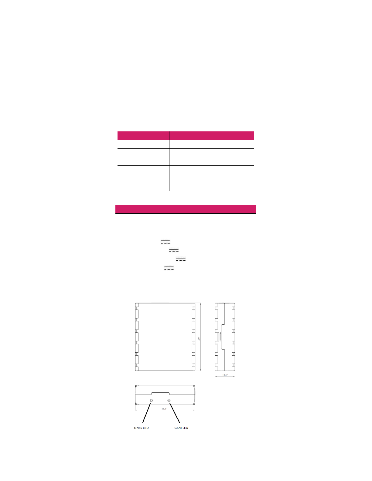
Measurements: 65x56.6x18.9mm
NAMES OF PARTS
PHYSICAL SPECIFICATIONS
Navigation LED
LED
Modem LED
LED
USB
Mini USB input
TECHNICAL DETAILS
Power supply 10 ...30V DC
2W Max
Consumption:
GPRS: 88 mA rms, 462 mA Max.
Nominal: Average 50 mA rms
GPS Sleep: Average 23 mA
Deep Sleep: On average, less than 2mA1
Operating temperature: -25°C to +55°C
Storage temperature: -40°C to +70°C
Relative humidity for storage : 5 ... 95% (No condensation)
MOBISAT® ROCK - User Manual v.2.0.3 - www.mobisat.eu - Page 5 of 16
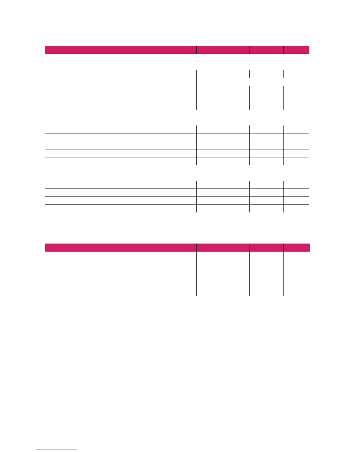
ELECTRICAL SPECIFICATIONS
DESCRIPTION
Min.
Type
Max.
Unit
Supply Voltage:
Supply voltage (recommended operating conditions)
10 30
V
Digital outputs (discharge rate)
Current drain (Digital Output OFF)
120
uA
Current drain (Digital Output ON, Operating conditions)
300
mA
Power Static Discharge (Digital Output ON)
300
mOhm
Digital Inputs:
Input Resistance (DIN1, DIN2, DIN3)
15
kOhm
Input Voltage (recommended operating conditions)
0 Supply
Voltage:
V
Input voltage threshold (DIN1)
7.5 V
Input voltage threshold (DIN2, DIN3)
2.5 V
Analog Inputs:
Input Voltage (recommended operating conditions), Range 1
0 10
V
Input Resistance, Range 1
120 kOhm
Input Voltage (recommended operating conditions), Range 2
0 30
V
Input Resistance, Range 1
146.7
kOhm
MAXIMUM RATINGS
DESCRIPTION
Min.
Type
Max
Unit
Supply Voltage (Absolute Max. Value)
-32 32
V
Drain-Source clamp threshold voltage (Absolute Maximum Ratings),
(Idrain = 2mA)
36
V
Digital Input voltage (Absolute Maximum Value)
-32 32
V
Analog Input Voltage (Maximum Absolute Value)
-32 32
V
 Loading...