

MOBILUS COSMO, WT User Manual
User manual of
COSMO | WT controller.
www.mobilus.pl
1. GENERAL INFORMATION
COSMO | WT is a 1-channel remote controller for wall mounting, designed for remote
control receivers brand MOBILUS (radio remote controls for roller shutters, awnings, blinds /
control modules for motors without radio communication module / ON / OFF modules).
• Support 1 channel.
• Support 1 channel group.
• Bi-directional communication - the opportunity to receive additional feedback information
from receivers.
Remote COSMO | WT - a remote control with touch screen keyboard. It has the ability to
control with the motions.
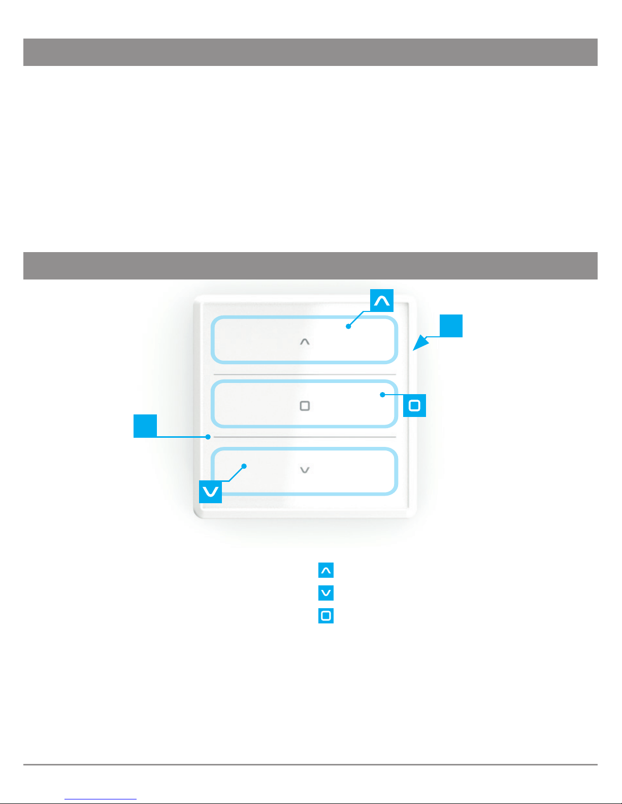
2. DESCRIPTION OF THE REMOTE CONTROL
1
5
1 The touch screen of remote control
COSMO | WT.
2 Battery compartment 2 x AAA.
3 The upper, main housing of remote
COSMO | WT.
4 The rear housing flap mounted to the wall.
Control button / navigation area - UP.
Control button / navigation area - DOWN.
Control button / navigation area - STOP.
P1 Function button 1.
P2 Function button 2.
2
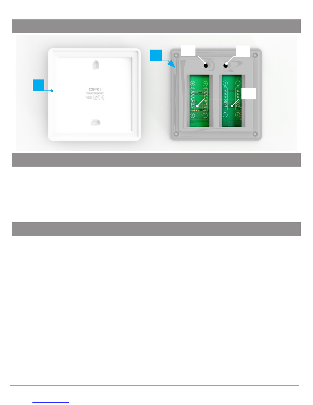
CONTINUED 2. DESCRIPTION OF THE REMOTE CONTROL
4
P2
2
3
P1
3. CONTENTS OF THE PACKAGE
The packaging contains the following items:
• remote COSMO | WT,
• 4 AAA batteries in the remote control protected against discharging with a seal,
• user manual,
• fixing pins (2 pcs.).
4. TECHNICAL PARAMETERS
• Radio protocol: COSMO
• Frequency: 868 [MHz]
• Dynamic code
• FSK modulation
• The supply voltage 3,0 V DC .
• Power source: batteries 4 x AAA LR03.
• Working temperature [ oC ]: 0-40oC.
• Display: touch screen with illuminated fields.
• Range in building: 40 [m]. The range of the radio signal depends on the type of construction, used materials and placement of units. The transmition of the radio signal in
different conditions is as follows: brick wall 60-90%, reinforced concrete 2,060%, wooden
structures with sheets of plasterboard 80-95%, glass 80-90%, metal walls 0-10%.
• Buzzer - tone generator.
• Dimensions: 80 x 80 x 20 mm.
3
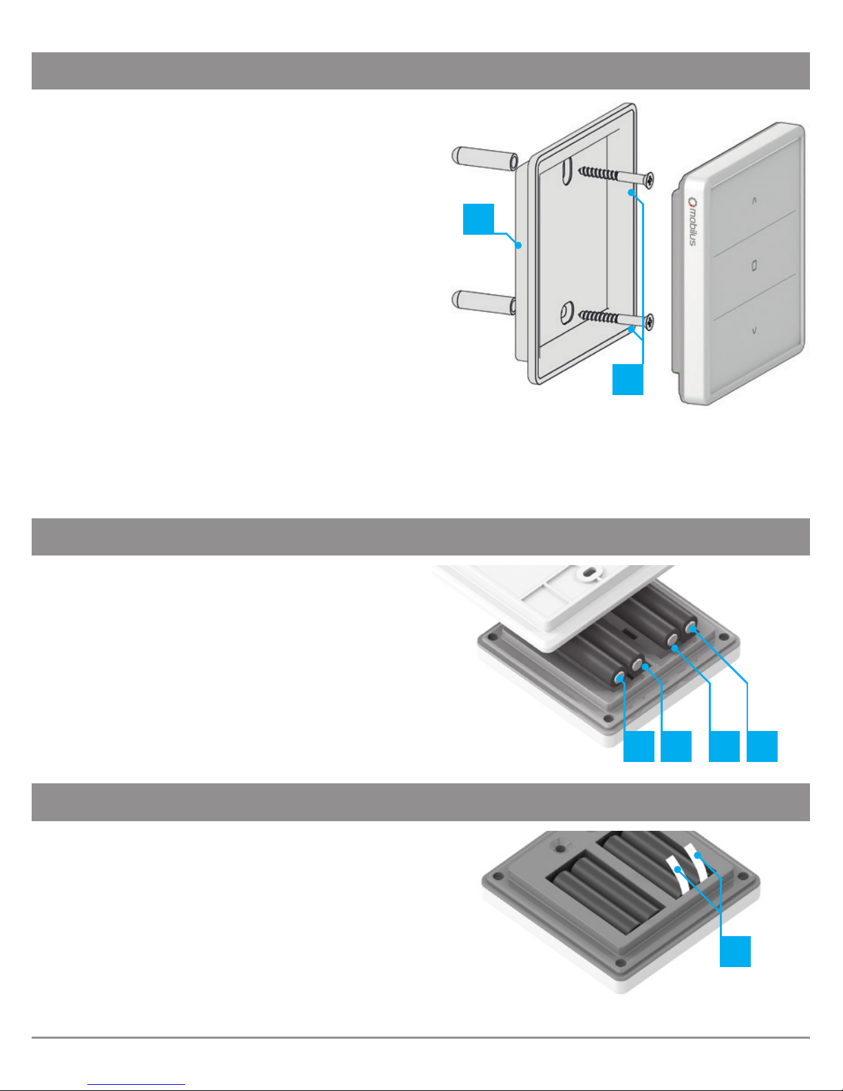
5. ASSEMBLY OF A HOLDING FIXTURE
Elements of wall handle:
• rear housing of remote - A,
• anchors with screws - B.
1. Determine the position where the rear flap
of housing will be located (easy access, no
running power cables, pipes, reinforcement
of walls, etc.).
2. Determine the points on the wall so that the
rear housing after assembly will adhere to
the wall and will be mounted perpendicular
to the ground.
A
B
3. Drill the holes and place the assembly anchors
(distance between the holes 36 mm, diameter 3.5 mm).
4. Attach the handle and tighten it to the wall.
5. Place front housing of the remote control to screwed flip.
6. POWER SUPPLY
The device is powered by four batteries
AAA LR003.
In order to change the battery, disconnect the
upper housing remote from parts mounted
on the wall.
-- --
7. THE INITIAL COMMISSIONING
The device is factory protected against battery
wearing. To the deprotecion:
1. Open the battery cover
2. Remove the seal Z, which protects the
batteries from discharging (marked
in white).
Z
4
 Loading...