

Mobile Watchman DVR-HD1 Installation And Operaion Manual
Mobile Vehicle Video Recorder
MobileWatchman DVR

SAFETY PRECAUTIONS
All the following safety and operation instructions which will prevent harm or damage to the operator or
other persons should be read before the unit is operated.
This equipment has been tested and found to comply with the limits for a Class A digital device,
pursuant to Part 15 of the FCC Rules. These limits are designed to provide reasonable protection
against harmful interference when the equipment is operated in a commercial environment. This
equipment generates, uses, and can radiate radio frequency energy and, if not installed and used
in accordance with the instruction manual, may cause harmful interference to radio
communications.
Operation of this equipment in a residential area is likely to cause harmful interference in which
case the user will be required to correct the interference at his own expense.
!
To reduce the risk of fire or electric shock, do not expose this appliance to rain or moisture.
!
Do not block ventilation openings.
!
Do not place anything on top of the unit that might spill or fall into it.
!
Do not attempt to service this unit yourself as opening or removing covers may expose you
to dangerous voltage or other hazards. Please refer all servicing to qualified service
personnel.
!
Do not use liquid cleaners or aerosols for cleaning.
!
This inst allation should be made by a qualified service person and should conform to all local
codes.
To prevent fire or electric shock, do not overload wall outlets or extension cords.
This unit must be grounded to reduce the risk of electric shock hazard.
!
Danger of explosion if battery( RTC Battery ) is incorrectly replaced. Replace only with the
same or equivalent type recommended by the manufacturer. Dispose of used batteries
according to the manufacturer’s instructions.
!
Risk of explosion if replaced by an incorrect type. Dispose of used batteries according to
the instructions.
INFORMATION
WARNING
CAUTION
1

CONTENTS
1. INTRODUCTION ................................. 3
1.1 YOUR DRIVING HELPMATE .................3
1.2 Product Introduction................................4
1.3 Product Features ....................................5
1.4 ACCESSORIES......................................6
1.5 FRONT / REAR VIEW ............................7
1.5.1 Front View..............................................7
1.5.2 Rear View...............................................9
1.5.3 Inner Host Rear View...........................10
1.5.4 GPS Connector....................................10
1.5.5 Camera In Connector...........................11
1.5.6 Power Delay Connection .....................11
1.5.7 Power Connector.................................12
1.6 I/O Port..................................................13
1.7 I/O Connection......................................14
1.8 Voltage Management............................15
2. INSTALLATION................................. 16
3.4 Search Operations............................... 25
3.4.1 FULL LIST Search........................... 25
3.4.2 ALARM LIST Search....................... 25
3.4.3 TIME Search .................................... 26
3.4.4 THUMBNAIL Search....................... 26
3.4.5 The SD CARD Search.................... 27
3.5 Backup Operations............................... 28
3.5.1 SD Card Backup Operations......... 28
3.6 The Key Lock Operation ...................... 29
4. MENU SETUP....................................30
4.1 REC Setting ......................................... 30
4.2 The ALARM Setting ............................. 32
4.3 The CLOCK/ TITLE Setting.................. 33
4.4 The COMMUNICATION Setting........... 34
4.5 DISK Setting......................................... 34
4.6 The SYSTEM Setting........................... 35
6. OTHER...............................................37
2.1 Basic Connection..................................16
2.2 Hard-disk Drive Installation...................18
2.3 System Information and........................19
Channel Selection.......................................19
2.3.1 System information..........................19
2.3.2 Channel Selection................................19
2.4 Updating System Software ...................20
3. OPERATIONS ................................... 21
3.1 Configuring Recording Settings............21
3.2 Recording Operations...........................23
3.2.1 Manual Recording............................23
3.2.2 Alarm Recording...............................23
3.2.3 Externally Triggered Recording......23
3.3 Playback Operations......................24
3.3.1 Normal Playback..............................24
3.3.2 Fast Forward/Backward..................24
3.3.3 Slow Forward/Reverse....................24
5.1 The RS-232 Setup & Protocol.............. 37
5.1.1 The RS-232 Protocol........................... 37
5.1.2 The Communication Protocol.............. 37
5.2 System Default..................................... 40
5.3 O.S.D Message.................................... 41
5.4 Time Index Table ................................. 42
5.5 Specifications....................................... 43
APPENDIX 1. – HDD Viewer..................... 44
1 Connection Application Software Installation.
..................................................................... 44
2. The PaPaGo Electronic Mapping Setting. 50
3. The HDD Viewer Setup............................ 51
4. The Working Screen................................. 52
APPENDIX 2. – FAQ.................................. 53
APPENDIX 3. – Changing the built-in hard
disk of the mobile DVR............................ 54
APPENDIX 4. – Vehicle Cameras.............. 57
3.3.4 Play back picture-by-picture...........25
2

1. INTRODUCTION
1. INTRODUCTION
1.1 YOUR DRIVING HELPMATE
1. Reliable real time recording of vehicle interiors as well as surrounding road
environments.
2. Portable inner host, easy to extract and carry wherever and whenever you like as
well as install in any outer casing.
3. Records the information from the GPS and uses the eMap software to show the
exact route of your vehicle at any given time.
4. Provides clearer and more accurate video records.
5. Easy to connect to a PC via a USB interface after the inner host has been taken
out of its outer casing.
6. Captures all your vehicle-related information from the data box in your video
records. This will prove to be invaluable evidence in case of any road incident or
accident.
3

INTRODUCTION ( continued )
1.2 Product Introduction
The DVR-HD1 is an advanced vehicle video recorder. It can simultaneously disp lay real-time images from
four cameras along with information data through the mobile video recorder directly onto your monitor. The
mobile DVR has four video channels which you can access either in the quad mode or single channel.
We use a hard disk device in this mobile recorder to store your images over a longer time. The recording
device has further already been tested for shock-proof and extreme temperature-proof durability in rugged
environments, with ventilation holes provided to lower the internal temperature for cooling.
The special design of the DVR enables you to easily retrieve the recording hosts inside, whic h are handy and
portable enough to carry anywhere you want and link up with PCs and TV monitors for direct display.
The DVR-HD1 includes the Global Position System (GPS) whic
information -- the GPS information can a
route. The DVR can also be connected to the car's information Black Box to access a vehicle's driving
speed , engine RPM, wheel turns, driving time periods, braking, signal lights, and so on, all of which data is
received and saved by the DVR. While searching for information, any important image you may want to save
can be stored via an SD card.
This mobile recorder provides all the above practical and useful features you can expect of it. It's your best
choice out of the entire range of mobile video recorders available. This multi-functional mobile video
surveillance product protects the safety of both the driver and the passengers.
lso be displayed by eMap Software to know about a car's exact
h helps disclose a vehicle's location
4

1.3 Product Features
Quad-based operation: real-time operation and playback (30 FPS/ per channel ).
M-JPEG compression with resolution up to 720X480 (NTSC) / 720X576 (PAL).
4x 6-pin Din connectors for AV inputs.
4 camera audio inputs, 2 auxiliary audio inputs, 1 audio output.
The HDD's video records can be plugged in and played back on a TV directly.
Pre-alarm image recording.
USB interface showing video records in a PC.
1 fixed 2.5" IDE HDD as storage medium for extended continuous digital recording.
Supports GPS (RS-232).
GPIO: 4 inputs and 2 outputs.
Operation power: DC 11~14.5 V.
Operation temperature: Standard HDD: 0 – 45℃ (32 –113℉)
Industrial HDD: 0 – 60℃ (32 –140℉)
Dimensions: 178 x 173 x 50 mm.
Time-lapse and real-time recording.
Refresh rate up to 30 IPS (25 IPS for PAL).
Image quality selectable at 4 different levels for recording.
Alarm recording mode.
Quick search by time, alarm, event, and recording list.
Fast and slow playback of recorded video at various speeds.
Single-picture playback.
On-screen setup menu, title and system timer.
Password protection.
Disk-full warning and operation status LEDs.
RS-232 communication port.
Remote controller.
Operation-status record log.
Automatic detection of the current voltage.
Audio function included.
Built-in SD card slot for copying images to an SD card.
Watermark.
Window Division.
Vibration and mechanical
shock protection.
5
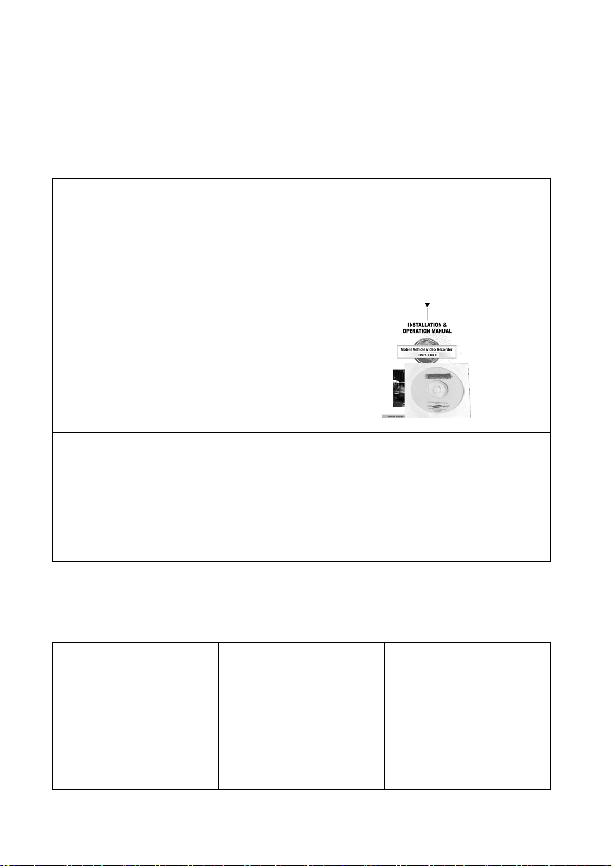
1.4 ACCESSORIES
The device package contains the following items:
Shockproof unit x 1.
Mini USB cable x 1.
Mini Din Splitter x 4– connects all kind s of professional CCTV cameras.
User Manual and CD x 1.
Adapter 5V x 1.
Shockproof unit x 1 Mini USB cable x 1
Mini Din Splitter x 4 User Manual and CD x 1
Adapter 5V x 1
The optional accessories contain the following items:
GPS GR213 (optional).
Mobile Power Adapter MADS12.6D3.5B (optional).
RC-5013 (optional).
GPS GR213 (optional) MADS12.6D3.5B (optional) RC-5013 (optional)
6
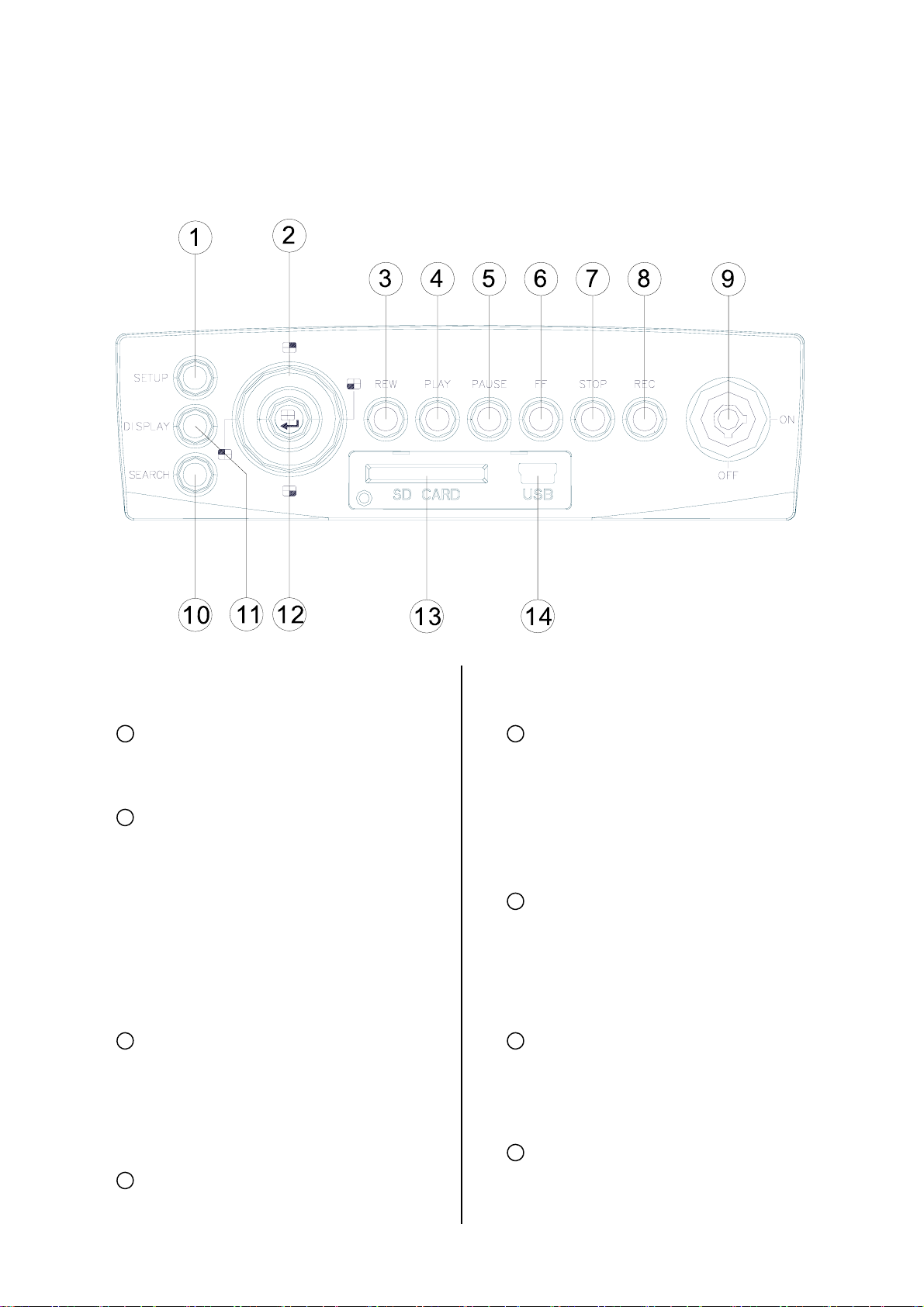
1.5 FRONT / REAR VIEW
1.5.1 Front View
1
SETUP button:
Press this to enter the setup menu. Press
again to exit the setup mode.
2
Left/ Right/ Up/ Down (CH1/ CH2/
CH4/ CH3) buttons:
In the menu setup mode / search mode,
press the four buttons on the dial to
highlight desired items in the menu
setup mode. In the live / play mode,
press the four buttons on the dial to
select a channel for display.
3
REW button:
Press this to play a recorded video in
from the hard disk. (A light glows green
in the PLAY mode.)
5
PAUSE button:
In a playback display, press this to
freeze the display. During the freeze,
press to display one frame of a picture
at a time in the forward direction (A light
glows red in the PAUSE mode.)
6
FF button:
Press this to play a recorded video in
the forward direction at a speed that's
faster or slower than the recorded speed
in the play mode
7
STOP button:
Press to stop playing back a recorded
the reverse direction at a speed that's
faster or slower than the recorded speed
in the play mode.
4
PLAY button:
Press to play back a recorded video
7
video. (A light glows red in the STOP
mode.)
8
REC button:
Push to start recording video into a hard
disk while in the live display mode. (A light

glows red in the REC mode.)
9
Inner-case lock:
This key lock secures the inner case
with the hard disk in place. When you
lock it in, it powers on the device. When
you unlock this key and take out the
inner case, the power turns off
automatically.
10
SEARCH button:
Press to enter the search mode to
access the recorded video.
11
DISPLAY button:
Press to show the system operation
status on the screen.
12
Enter / (Quad) button:
Press to enter a selected item and save
the setting in the menu setup mode. In
the live/ play mode, use this button to
show a quad display.
13
SD CARD slot:
This is used for system software
updating and archiving/ accessing of
critical images.
14
USB port:
This is used for system picture playing.
Use this port to connect with your PC or
notebook. You can easily and quickly
capture data from a hard disk in the
vehicle DVR.
8
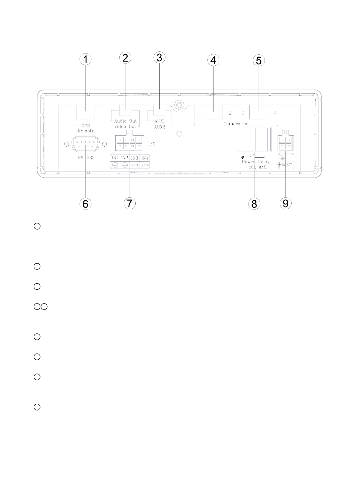
1.5.2 Rear View
1
GPS & Remote Controller Connector:
The left side connector links up with the GPS receiver to capture local position information data.
Please refer to the section 1.5.4 GPS CONNECTOR. The right side connector links up with the
remote controller
2
Audio Out / Video Out:
Your LCD monitor or other monitor can signal here.
3
AUX 1 / AUX 2:
Use this if you have external audio sources.
4 5
Camera In connector:
There are four connectors here to connect the Video / Audio In from a camera. Please refer to the
section 1.5.5 CAMERA IN CONNECTOR.
6
RS 232 port:
This communication port functions as a connector to an external device, for example a data box.
7
I / O port:
This connector links up with an external device.
8
Power Delay:
This connector will avoid the vehicle device getting excess power. Please refer to section 1.5.6
POWER DELAY CONNECTION.
9
Power Input:
This connector links up with the power from the vehicle (12V). Please refer to section 1.5.7 POWER
CONNECTOR.
9
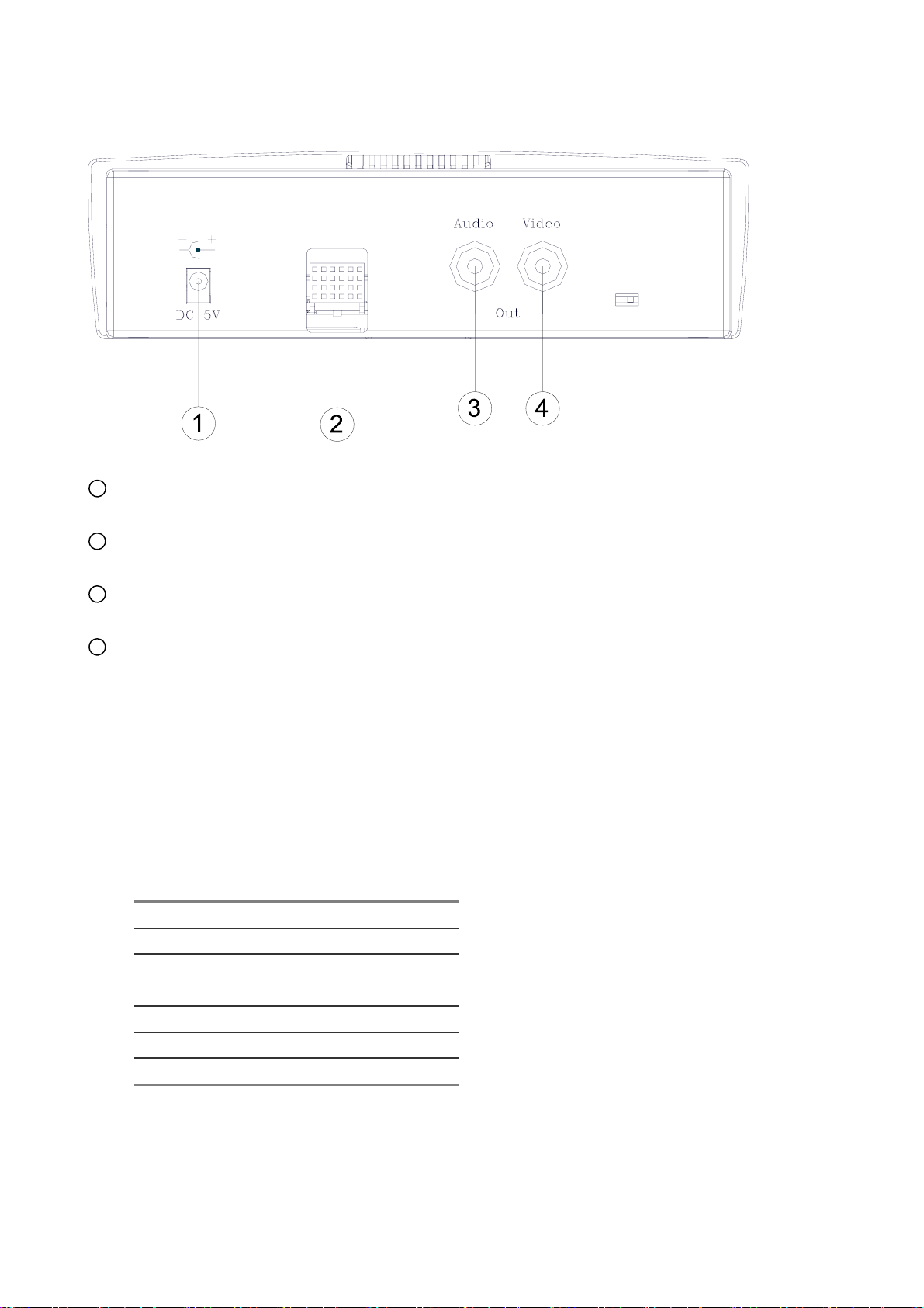
1.5.3 Inner Host Rear View
1
Plug Inlet:
The inlet connects to an external power supply. Connect to 5V DC UL Listed Class 2 Power Supply.
2
Hard Metric Connector (Male):
This connector links up with the outer casing.
3
Audio Connector:
Connect here to hear the audio's sound when you play the inner host case outside the outer case.
4
Video Connector:
Connect here to play the video when you play the inner host case outside the outer case.
1.5.4 GPS Connector
(PS/2 composition of male connector)
PIN NO.
1.
2.
3.
4.
5.
6.
PIN Assignment
+ 5V DC
Not Connected
RX
Ground
TX
Not Connected
10

1.5.5 Camera In Connector
(PS/2 composition of female connector)
PIN NO. PIN Assignment
1.
2.
3.
4.
5.
6.
Note: The maximum electric current provided for 4 mobile cameras is 1 ampere ( 1A ) in total.
Not Connected (Mirror)
Audio In
+ 12V DC
Video In
Ground
Ground
1.5.6 Power Delay Connection
This connector will avoid the vehicle device getting excess power.
11

1.5.7 Power Connector
1
GND: Ground contact.
2
Not used.
3
12 V: This pin is connected to the vehicle battery.
4
ACC: This pin is linked to the vehicle ignition key to start the
DVR.
Pin connections with the ignition key
In the above diagram, pin 1 is connected to the
vehicle battery minus, pin 3 to the battery plus,
and pin 4 to the vehicle ignition key.
Pin connections without the ignition key
I. Connect with the Battery
In the above diagram, pin 1 is connected to the
vehicle battery minus, and pins 3 and 4 are
connected together to the vehicle battery plus.
II. Connect with the Cigar-lighter Connector
Note: If the mobile vehicle battery is over 16.1 volts or under 10.4 volts, the DVR will not work.
In the above diagram, pin 1 is connected to the
Cigar-lighter Connector minus, and pins 3 and 4
are connected together to the Cigar-lighter
Connector plus.
12

1.6 I/O Port
This figure is seen from the rear view.
1. I/O IN1 (INPUT): This is an alarm input which can be programmed in the menu system to Normally
Open or Normally Closed.
2. I/O IN2 (INPUT): same as above.
3. I/O IN3 (INPUT): same as above.
4. I/O IN4 (INPUT): same as above.
5. GND: Ground Contact.
6. GND: Ground Contact.
7. I/O OUT1 (OUTPUT): This is an alarm output trigger. Connect this to external devices such as
buzzers or lights.
8. I/O OUT2 (OUTPUT): This is an alarm output trigger. Connect this to external devices such as
buzzers or lights.
13

1.7 I/O Connection
ALARM:
In the "MAIN MENU" page, click "ALARM" to enter the "ALARM" page. In this page, go to the "I/O
CONNECTION" item which has two options, "ALARM" and "VEHICLE SIGNAL". If you choose "ALARM", the
I/O port will change its meanings:
pins 1, 2 and 3 will become an alarm input which can connect with three different sensors and receive a
trigger; pin 4 can receive the "Reset" trigger; pins 5 and 6 are ground contacts; pin 7 can se nd out an alarm
output trigger from pins 1, 2 and 3, and connect to external devices like buzzers or lights; and pin 8 is N/A
(not applicable).
VEHICLE SIGNAL:
In the "MAIN MENU" page, click "ALARM" to enter the "ALARM" page. In this page, go to the "I/O
CONNECTION" which has two options, "ALARM" and "VEHICLE SIGNAL". If you choose "VEHICLE
SIGNAL", the I/O port will change its meanings:
pin 1 will connect with the leftside car signal light and receive the trigger signals; pin 2 will connect with the
rightside car signal light and receive the trigger signals; pin 3 is N/A (not applicable); pin 4 can connect with
the car stopping signal light to receive the brake triggering signals; pins 5 and 6 are ground contacts; pin 7
and 8 are N/A (not applicable).
14

1.8 Voltage Management
You can display the system - setting information after you press the "DISPLAY" button on the front panel. On
this screen you can see the battery voltage icons. Please consult the above diagram to know the battery
voltage status.
Between 10.4 volts and 16.1 volts, the battery is in the "Working" mode.
Between 11.3 volts and 15.2 volts, the battery is in the "Standard" mode.
Between 10.4 volts and 11.3 volts, the battery is in the "Low" mode.
Between 15.2 volts and 16.1 volts, the battery is in the "High" mode.
If the voltage is less than 10.4 volts, the battery is in the "Too low" mode", and the DVR will automatically
power off after 1 minute of beeping.
If the voltage is more than 16.1 volts, the battery is in the "Too high" mode, and the DVR will automatically
power off after 1 minute of beeping.
Note: 1. After the car motor is switched on ( ACC-On ) for 3 minutes, even if the voltage is too high or too low,
the DVR won't shut down, only beep.
2. When the car motor is switched off ( ACC-Off ), the DVR will power off, too, after 1 minute of beeping.
15

2. INSTALLATION
2. INSTALLATION
2.1 Basic Connection
Mobile Video Surveillance Solution
This is the mobile DVR, our video surveillance device for durable use in the vehicle. It's a
multipurpose, multi-source, multi-media device for monitoring your vehicle, pinpointing its
route and location, and recording and playing vital incidents related to it, in the interests of
vehicle security and welfare.
The mobile DVR provides advanced text insertion technology that is compatible with
mobile black boxes which record all the relevant details of driving. For example, all
information regarding the driving speed, engine RPM, wheel turning angles, driving time
periods, brakings, signal lights, and the GPS position can be retrieved from the black box
system. The data can be stored, recorded and transferred to a computer or to the mobile
DVR directly for data storage and retrieval to ensure a car fleet’s and/ or individual driver’s
quality performance.
The mobile DVR is compatible with the stand-alone GPS receiver, and it can also
configure and record a driver’s location (latitude and longitude) with video data. Besides, it
can playback video by our HDD viewer software, which can track a driven route using all
GIS/e-Map software.
16
 Loading...