

Page 1
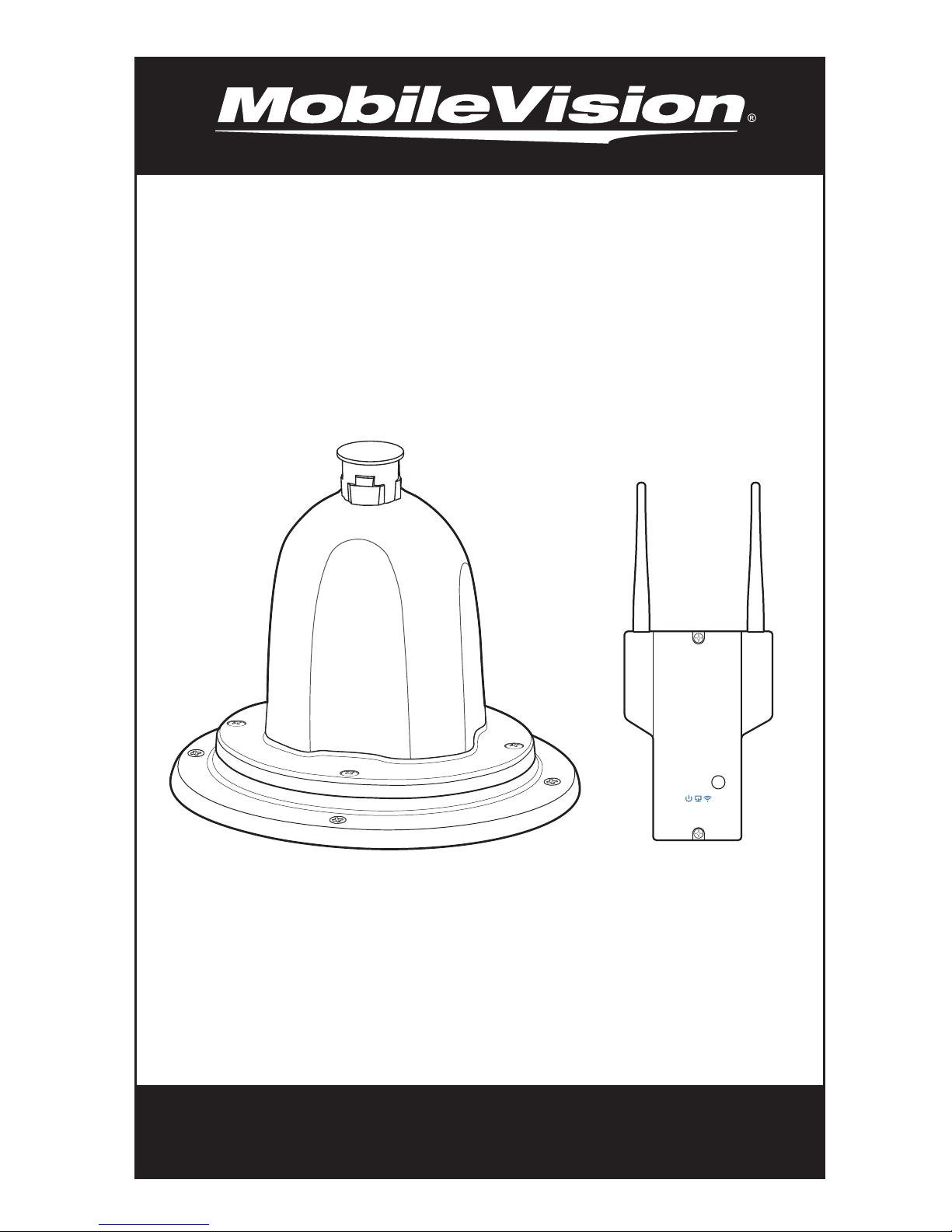
Wireless or Cabled WiFi System
Installation Manual
WiFi Extender
For Technical Assistance, please call (800) 638-3600,
MV2458 Router
Control Unit
Model: MV100
or visit www.magnadyne.com
Page 2

MV100 WiFi System Installation Manual
Thank you for purchasing the MobileVision MV100 wireless
WiFi extender kit. The MV100 is designed for easy installation with a
professional appearance in your RV. To install the MV100 you will need
a basic understanding of installing 12 volt devices in your RV. If you are
not comfortable with the installation process after reviewing the
installation manual we recommend you have the product professionally
installed.
Attach MV2400 Product Identification Label below.
2
Page 3

Installation Options
The MV100 is designed to provide 2 methods of installation to best
fit the unique needs of the RVs design and layout. Be sure to read
through the instructions and determine your desired method of
installation before you begin.
Option 1 - Wireless (12V wiring only) - no Ethernet cable required
The wireless option is designed to be used in installations where
routing an Ethernet cable from the inside to the outside of the RV is
difficult. The connection between the MV2400 Extender and the
MV2458 router is established wirelessly. (page 6)
Option 2 - Wired using Ethernet Cable
The wired by Ethernet installation method utilizes an Ethernet cable
and POE (power or Ethernet) to connect the MV2400 Extender and
MV2458 Router. The MV2400 Extender receives its power over the
Ethernet cable. (page 16)
Table of Contents
Parts and Tool List ........................................................
MV2458 Router Control Unit Wireless Installation........
MV2400 Extender Wireless Installation.........................
MV2458 Router Control Unit Ethernet Installation.......
MV2400 Extender Ethernet Installation.......................
Warranty Policy...........................................................
16
18
20
4
6
8
3
Page 4
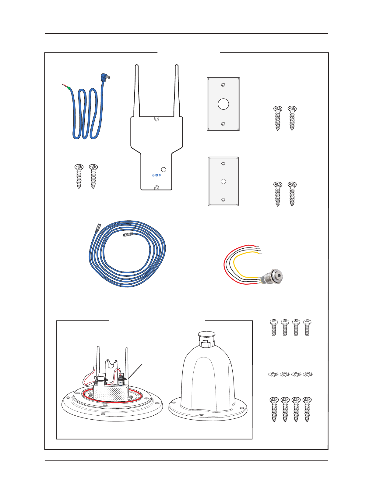
Parts and Tool List
Kit Includes
Blue Power Cord
MV2458 Router
Control Unit
MV2458 Router
Screws (2)
WET-15
Shielded Ethernet Cable
Control Unit
Cover Plate
Ceiling Plate
MV2400 Power Switch
Cover Plate Screws (2)
Ceiling Plate Screws (2)
MV2400 Extender Housing
Extender Housing Bottom Mount
4
MV2400
Extender
Top Mount
#10-24 UNC
Threaded Machine
Screws (4)
Lock Washers (4)
Self Tapping
Screws #8 (4)
Page 5
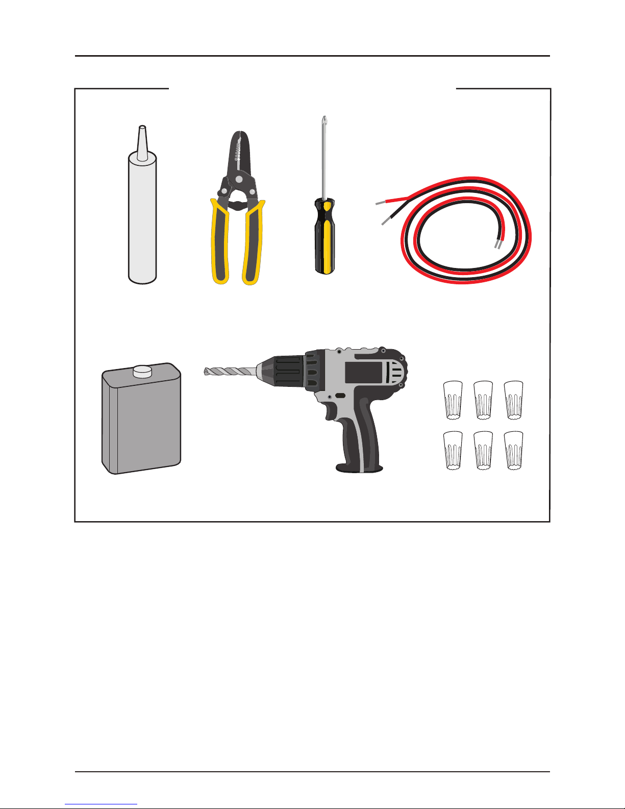
Roof Sealant
Recommended Tools and Supplies
+
-
Phillips
Wire Strippers
Screwdriver
20 or 18 Gauge Wire
Surface Cleaner
5
Drill
Connectors (6)
(i.e. Wire Nuts)
Page 6
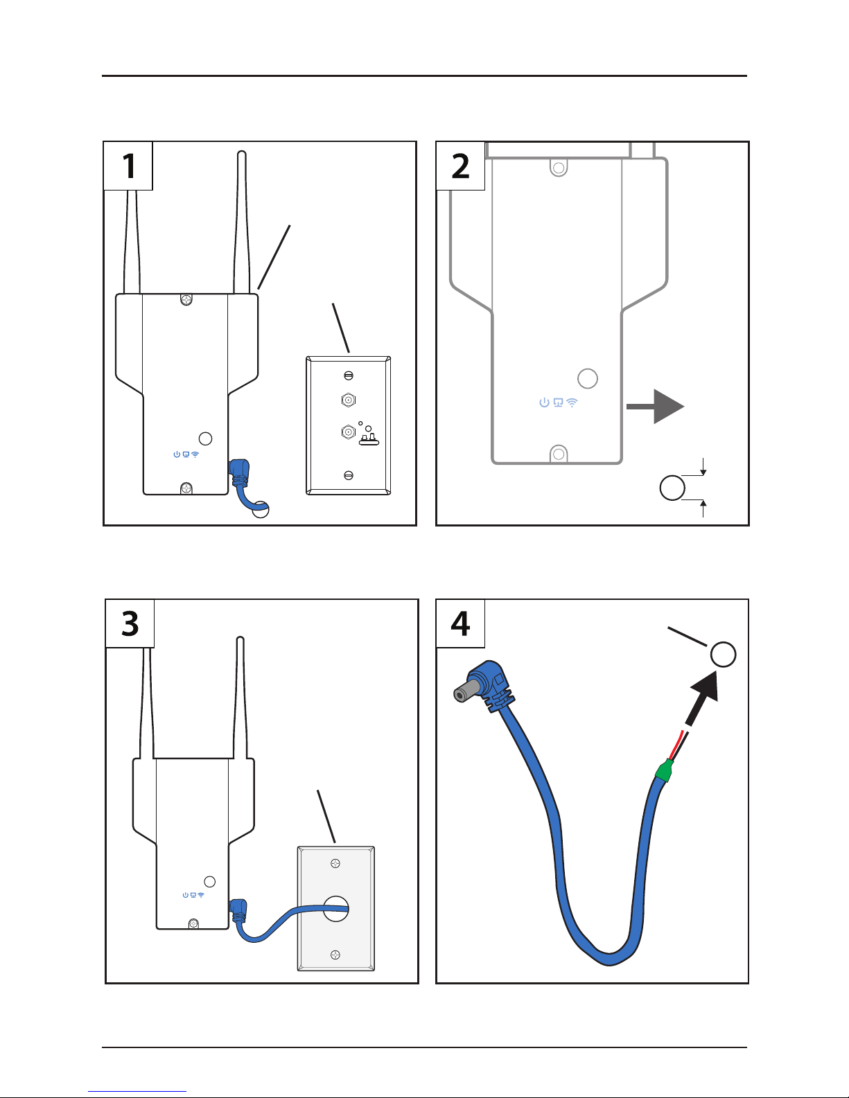
MV2458 Router Control Unit Wireless Installation
Disconnect the RV power source before beginning installation, and reconnect
power after installation is complete.
MV2458
Router
Control Unit
TV Distribution
Wall Plate
(to the Right)
Satellite
ON OFF
TV 1
ON = TV
OFF = Cable
Locate a 12V power source for the MV2458 Router
Control Unit (such as a TV Distribution Wall Plate) that
is near to where you plan to mount the MV2458 Router.
Alternative
Option
Cover Plate
1/4”
Drill a 1/4” hole in the wall to the Right of where the
MV2458 Router will be installed.
Drilled Hole
If you need to drill a larger hole, you can use the
provided Cover Plate to route the Blue Power Cord
through and cover the hole.
6
Insert end of Blue Power Cord into drilled hole and
route Blue Power Cord to power source.
Page 7

Blue
Power Cord
Ground
Back of TV antenna
distribution wall plate
MV2458
Router
Control Unit
12V(+)
Connectors
Black
Attach the Blue Power Cord’s red wire to a 12V(+)
power source and the black wire to a 12V(-) ground
and secure with connectors.
WARNING - Red Wire must connect to 12V(+) wire
from the vehicle, & Black Wire must be connected to
12V(-)wire from vehicle.
Red
Mount MV2458 Router Control Unit to wall near the
Blue Power Cord as pictured using MV2458 Router
Control Unit Screws.
Please Note
Roof Extender Only
MV2458 Bottom View
Plug the Blue Power Cord into MV2458 Router
Control Unit.
7
Can Cause Damage
to Your Computer
or Other Devise
MV2458 Router Control Unit Wire-
less Installation is Complete
Page 8

MV2400 Extender Wireless Installation
Hole Option A
(Rooftop)
Power
1
Source (i.e. fan)
Extender
2
Switch
Hole to
3
MV2400
Extender
(Inside RV)
DO NOT drill a hole into the roof UNTIL you have verified the exterior
mounting location of the MV2400 Extender Housing. Be sure to find
a location to mount the housing that is flat and away from large items
CAUTION
1 - Locate a 12V(+) power source on the RV Ceiling (such as exhaust fan or light input power) to power
the MV2400 Extender. This power source needs to be accessible to connect to the MV2400 power wires
as shown in Step 8.
2 - Choose a location near the power source to drill a hole in the RV Ceiling to install the Extender Switch.
This should be near or directly below where the MV2400 Extender Housing will be installed on the roof.
3 - In the determined location near the Extender Switch, drill a hole into the roof to later connect the
yellow and black wires from the Extender Switch to the MV2400 Extender.
like air conditioners that may cause interference.
When MV2400 Extender is not in use, a switch is needed to turn
off the MV2400 Extender so that the RV battery is not drained.
8
Page 9

Hole Option B
(Rooftop)
Power
1
Source (i.e. fan)
Extender
2
Switch
3
(Inside RV)
In this example the hole to the roof (for routing the power wires to the MV2400 Extender) is located
directly above the hole drilled in the ceiling that is used for installing the Extender Switch.
Hole to
MV2400
Extender
9
Page 10

MV2400 Extender Wireless Installation - Cont.
(Rooftop)
1/2”
(Back Side of
RV Ceiling)
(Inside RV)
After you have determined the location of the MV2400
Extender Housing on the roof, drill a 1/2” hole into the
RV ceiling to feed the 4 switch wires through.
(Rooftop)
(Back Side of
RV Ceiling)
(Inside RV)
Drill a 1/2” hole from the exterior roof where the
Extender Housing will be mounted over. This hole will
be used to route the power wires from the Extender
Switch to the MV2400 Extender in the housing.
(Rooftop)
(Back Side of
RV Ceiling)
(Inside RV)
If using one location for both holes drill one 1/2” hole
though the roof and the ceiling.
10
CAUTION - Before drilling from the
roof or inside, be sure that you
verified there are no obstacles in the
way on the inside or outside of the
RV such as ceiling lights, speakers,
air conditioners or wiring between the
interior ceiling and the exterior roof.
Page 11

Nut
Ceiling Plate
Extender Switch
1) Unscrew the nut from Extender Switch.
2) Route wires of Extender Switch through Ceiling Plate and Nut.
3) Attach the Extender Switch to the Ceiling Plate by screwing Nut back onto Extender Switch.
Do not mount the Ceiling Plate at this point.
Screw Nut
Tightly
Yellow and Black
Switch Wires
to MV2400 Extender
Red and Black
Switch Wires
to Power Source
Extender Switch
Ceiling Plate
1) Route the red and black Switch Wires to the Power Source to connect.
2) Route the yellow and black Switch Wires to the roof.
(Rooftop)
(Back Side of
RV Ceiling)
(Inside RV)
11
Page 12

MV2400 Extender Wireless Installation - Cont.
Connectors
(Rooftop)
12V(-) from RV
12V(+) from RV
(Back Side of
RV Ceiling)
RV Power
Source
(Inside RV)
Attach the red and black Switch Wires from the Extender Switch to the
selected 12V power source using Connectors.
Wires from
Extender Switch
(Rooftop)
(Back Side of
RV Ceiling)
Feed the yellow and black Switch Wires from Extender Switch through the
hole drilled in roof and center tube of Extender Housing Bottom Mount.
12
Page 13

Self
Tapping
Screws #8
Bottom
Mount
RV
Roof
1) Center the Extender Housing Bottom Mount over drilled hole.
2) Screw the Extender Housing Bottom Mount to roof with Self Tapping Screws (#8).
2nd Level
1st Level
Caulk the Extender Housing Bottom Mount on 1st Level (shown in orange area).
WARNING - Do not caulk on the 2nd Level (where the Top
Mount connects to the Extender Housing Bottom Mount).
Caulking Area
Represented in
Orange
13
Page 14

MV2400 Extender Wireless Installation - Cont.
Black to Black
1) Attach yellow 12V(+) wire from Extender Switch to red wire 12V(+) of MV2400 using a Connector.
2) Attach black 12V(-) wire from Extender Switch to black 12V(-) wire of MV2400 using a Connector.
#10-24 UNC
Threaded
Machine
Screws
WARNING - Make sure the O-ring
is in place & screws are tight.
Yellow to Red
Lock
Washers
1) Place Extender Housing Top onto Extender Housing Bottom Mount. Make sure wires fit securely inside, are
not pinched, and do not interfere with MV2400 antennas.
2) Secure the Extender Housing Top to the Extender Housing Bottom Mount using 4 Machine Screws
(#10-24 UNC Threaded) and 4 Lock Washers provided.
14
Page 15

Attach the Ceiling Plate to the ceiling with the Ceiling Plate Screws.
(Rooftop)
(Back Side of
RV Ceiling)
(Inside RV)
Extender
Switch
1) Reconnect RV power source for MV2458 Router Control Unit and MV2400 Extender.
2) Turn on the power to the MV2400 Extender using the Extender Switch.
3) Turn on the power to the MV2458 Router Control Unit using the Router’s front power switch.
15
Router’s
front
power
switch
Page 16

MV2458 Router Control Unit Ethernet Installation
MV2400
Note: You do not need a Switch
and power supply for the
MV2458
MV2400 Extender as it will be
powered by the Ethernet cable.
Choose a way to route an Ethernet cable from the MV2400 to the MV2458.
Back of TV antenna
Blue
Power Cord
12V(+)
Ground
distribution wall plate
Satellite
ON OFF
TV 1
ON = TV
OFF = Cable
Blue
WiFi Cable
Black
Attach the Blue Power Cord’s red wire to a 12V(+)
power source and the black wire to a 12V(-) ground
and secure with connectors.
WARNING - Red Wire must connect to 12V(+) wire
from the vehicle, & Black Wire must be connected to
12V(-)wire from vehicle.
16
Connectors
Red
1) Drill a 1” hole in the wall near where the router is
later planned to be installed.
2) Route Blue WiFi Cable into hole and up to roof
where the Roof Mount hole will be drilled.
3) Bring the connected Blue Power Cable through
the drilled hole.
Page 17

MV2458
Control Unit
1) Bring Blue Ethernet and Blue Power Cables
through center hole of new cover plate.
2) Screw new cover plate to wall using original
mounting holes.
Mount Router Control Unit to wall near the
new cover plate as pictured using included
screws.
Please Note
Roof Extender Only
MV2458 Bottom View
Can Cause Damage
to Your Computer
or Other Devise
Connect Blue Ethernet and Blue Power Cables to
MV2458 Control Unit as pictured.
17
MV2458 Router Control Unit Ether-
net Installation is Complete
Page 18

MV2400 Extender Ethernet Installation
(Rooftop)
(Back Side of
RV Ceiling)
(Inside RV)
Self
Tapping
Screws #8
Bottom
Mount
RV
Roof
Drill a 1/2” hole from the exterior roof where the Extender Housing will be
mounted over. This hole will be used to route the WET-15 Shielded Ethernet Cable
from the MV2458 Router Control Unit to the MV2400 Extender in the housing.
Caulking Area
2nd Level
Represented in
Orange
1st Level
1) Center the Extender Housing Bottom Mount over
drilled hole.
2) Screw the Extender Housing Bottom Mount to roof
with Self Tapping Screws (#8).
18
Caulk the Extender Housing Bottom Mount on 1st
Level (shown in orange area).
WARNING - Do not caulk on the 2nd Level (where the Top
Mount connects to the Extender Housing Bottom Mount).
Page 19

Remove power cable plugged into MV2400 Extender.
Plug Ethernet cable into MV2400 Ethernet port. Zip
Tie the Ethernet Cable to the mount as shown to
reduce rattling.
#10-24 UNC
Threaded
Machine
Screws
Lock
Washers
WARNING - Make sure the O-ring
is in place & screws are tight.
1) Place Extender Housing Top onto Extender Housing Bottom Mount. Make sure wires fit securely inside, are
not pinched, and do not interfere with MV2400 antennas.
2)Secure the Extender Housing Top to the Extender Housing Bottom Mount using 4 Machine Screws (#10-24
UNC Threaded) and 4 Lock Washers provided.
19
Page 20

Warranty Policy
ONE (1) YEAR LIMITED WARRANTY
Magnadyne Corporation or its authorized agents will within one year from the date of
sale to you, repair, replace or refund the retail sales price of said product or any part
thereof, at the option of the Magnadyne Corporation or its authorized agents, if said
product or part is found defective in materials or workmanship, when properly
connected and operating on the correct power requirements designated for the
specic product. This warranty and Magnadyne Corporation or its authorized agent’s
obligations hereunder do not apply where the product was; damaged while in the
possession of the consumer, subjected to unreasonable or unintended use, not
reasonably maintained, utilized in commercial or industrial operations, or serviced by
anyone other than Magnadyne Corporation or its authorized agents, or where the
warning seal on the product is broken or the power and/or plugs are detached from the
unit. Magnadyne Corporation or any of its authorized agents will not assume any labor
costs for the removal and re-installation of any product found to be defective, or the
cost of transportation to Magnadyne Corporation or its authorized agents. Such cost are
the sole responsibility of the purchaser.
This warranty does not cover the cabinet appearance items or accessories used in
connection with this product, or any damage to recording or recording tape, or any
damage to the products resulting from improper installation, alteration, accident,
misuse, abuse or acts of nature.
MAGNADYNE CORPORATION OR ITS AUTHORIZED AGENTS SHALL NOT BE LIABLE TO
ANYONE FOR CONSEQUENTIAL OR INCIDENTAL DAMAGES OR CLAIMS EXCEPT THOSE
ACCORDED BY LAW. NO EXPRESSED WARRANTY OR IMPLIED WARRANTY IS GIVEN
EXCEPT THOSE SET FORTH HEREIN. NO IMPLIED WARRANTY SHALL EXTEND BEYOND
ONE YEAR FROM THE DATE OF SALE.
This warranty extends only to the original purchaser of the product and is not
transferable. Some states do not allow limitations on how long an implied warranty
lasts, and some states do not allow the exclusion or limitation of incidental or
consequential damages, so the above limitations or exclusion may not apply to you.
This warranty gives you specic legal rights, and you may have other rights that vary
from state to state.
“NOTE: The manufacturer is not responsible for any radio or TV interference caused by
unauthorized modications to this equipment. Such modications could void the User’s
authority to operate the equipment.”
Defective merchandise should be returned to the original point of purchase or
secondly, to Magnadyne Corporation, 1111 W. Victoria Street, Compton CA 90220.
Return Authorization must be obtained before sending, or merchandise may be
refused.
20
Copyright © 2017 Magnadyne Corp.
MOBILEVISION-MV100-IS Rev. A
 Loading...