

MobileView 9100, MVC-9100-28-BK, MVC-9100-28-WI, MVC-9100-40-WI, MVC-9100-60-WI Quick Manual
...
MobileView 9100 Series High
Resolution Analog/IP Camera Quick
Guide
1072870 A September 2014
© 2014 United Technologies Corporation, Inc. MobileView is
part of UTC Building & Industrial Systems, a unit of United
Technologies Corporation. All rights reserved.
Content
Introduction 1
Product overview 1
Installation Environment 1
Package Contents 1
Cable Requirements 2
Camera Description 2
Setting up the Camera 2
Mounting the Camera 2
Accessing the Camera over the Internet 3
Overview of the Camera Web Browser 3
Network and Streaming Configuration 4
FCC Complicance 4
Contact information 4
Introduction
Installation Environment
When installing your product, consider these factors:
• Electrical: Install electrical wiring carefully. It should
be done by qualified service personnel. Always use
a proper PoE switch or a 12 VDC power supply to
power the camera. Do not overload the power cord
or adapter. PoE and 12 VDC power sources should
not be used together; choose only one.
• Ventilation: Ensure that the location planned for the
installation of the camera is well ventilated.
• Temperature: Do not operate the camera beyond
the specified temperature, humidity or power source
ratings. The operating temperature of the camera is
between -20°C to +60°C.
• Servicing: Do not attempt to repair this camera
yourself. Any attempt to dismantle this product,
except as required for normal installation, will
invalidate the warranty and may also result in injury.
Refer all servicing to qualified service personnel.
Product overview
This is the Quick Guide for MobileView camera models:
MVC-9100-28-BK (Minidome camera, 2.8mm,
Black)
MVC-9100-28-WI (Minidome camera, 2.8mm)
MVC-9100-40-WI (Minidome camera, 4.0mm)
MVC-9100-60-WI (Minidome camera, 6.0mm)
MVC-9100-80-BK (Minidome camera, 8.0mm
Black)
1 MobileView 9100 Series High Resolution Analog/IP Camera Quick Guide
• Cleaning: Do not touch the lens with fingers. If
cleaning is necessary, use a clean cloth with some
ethanol and wipe the camera gently.
Package Contents
Check the package and contents for visible damage. If
any components are damaged or missing, do not
attempt to use the unit; contact the supplier immediately.
If the unit is returned, it must be shipped back in its
original packaging.
Package contents:
Camera
Y Splitter cable (optionally used if 12VDC power is
supplied via Cat5)
Hex wrench
Quick Operation Guide
Drill Template
Molex connector/pins
Molex adapter cable (2-pin to 3-pin, optionally used
with 12VDC power if analog audio is not required)
Lens adjusting tool
Cable Requirements
Setting up the Camera
To quickly put the camera into operation:
1. Prepare the mounting surface.
2 Mount the camera using the appropriate fasteners.
See the following “Mounting the Camera” section.
3. Set up the camera’s network and streaming
parameters so that the camera can be controlled
over the network. See section “Accessing the
Camera over the Internet.” For further information,
please refer to the “MobileView 9000 & 9100 Series
Analog/IP Camera User Manual”.
For proper operation, adhere to the following cable and
power requirements for the cameras. All network cabling
must be installed according to applicable codes and
regulations.
Table 1 below lists the requirements for the cables that
c
onnect to the camera. Note that the camera has two
options to receive power; only one should be used at a
time.
Table 1: Recommended power cable requirements
PoE(802.3af):
12VDC:
Cat5, or better
18 AWG, or larger
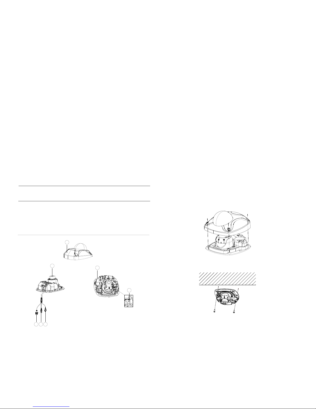
Camera Description
Figure 1: MVC-9100 Minidome Camera
1
2
7
4. Program the camera to suit its location. For further
information, please refer to the “MobileView 9000 &
9100 Series Analog/IP Camera User Manual”.
Mounting the Camera
To Mount the Minidome Camera:
1. Use the supplied template to mark out the mounting
area. Drill the screw holes on the surface.
2. Loosen the cover screws to remove the cover from
the camera.
3. Fix the mounting base to the ceiling with appropriate
screws.
3
5
4
1. Cover
2. Lens
3. Ethernet RJ45
4. BNC Cable
5. 12VDC/audio Molex connector
6. Reset button
7. Base
2 MobileView 9100 Series High Resolution Analog/IP Camera Quick Guide
6

4. Align the supplied adjusting tool to the small holes
on the camera.
To access the camera online:
1. In the Web browser, enter the camera’s IP address
(default is 192.168.1.70). The Login dialog box
appears.
Note: Ensure that the Active X controls are enabled.
5. Loosen the adjusting screw to adjust the pan, tilt and
rotation angle with the adjusting tool, then re-tighten
the adjusting screw.
6. Visually check to ensure that you did not
accidentally rotate the foam ring around the lens –
both of the small lens adjusting holes should still be
visible. Also check to ensure the rubber cap is still
present over the microphone.
MicrophoneFoam
2. Enter your user name and password.
User name: admin
Password: 1234
3. Click Login. The web browser window appears in
live view mode. See Figure 2.
Overview of the Camera Web
Browser
Figure 2: Camera Web browser interface
7. Re-install the cover using the cover screws.
Accessing the Camera over the
Internet
Use the camera web browser to access and configure
the camera over the internet (Microsoft Internet
Explorer). Only one camera is accessible from a single
web browser window.
Item Name Description
1. Live view Click to view live video.
2. Configuration Click to display the configuration
screen for setting up the camera.
3. Current user Displays current user logged on.
4. Logout Click to log out from the system. This
5. Start/stop live view Click to start/stop live view.
6. Capture Click to take a snapshot of the video.
7. Start/stop
recording
8. Digital Zoom Click to enable digital zoom.
can be done at any time.
The snapshot will be saved to the
default folder in JPEG or BMP format.
Click to record live video.
MobileView 9100 Series High Resolution Analog/IP Camera Quick Guide 3

Network and Streaming
Configuration
In the camera Web browser screen click the
Configuration button on the toolbar to display the
configuration screen. See Figure 3.
FCC Complicance
Complies with FCC Part 15; Class A.
Figure 3: Configuration screen
Refer to the “MobileView 9000 & 9100 Series Analog/IP
Camera User Manual” for detailed information on
configuring the cameras. See Table 2 for an overview of
the config
Table 2: Overview of the configuration parameters
Configuration folders Description
Local configuration Defines the protocol type, live view
System Displays device information including serial
Network Defines the network parameters required to
Video/Audio Defines recording parameters for each of
Image Defines the image parameters, OSD
Security Defines who can use the camera, their
Events Defines motion detection, tamper-detection,
Storage Defines snapshot configurations.
ion parameters.
urat
performance and local storage paths.
number and firmware version. Defines time
settings, maintenance and RS232
parameters.
access the camera over the internet.
the three streams.
settings, overlay text and privacy mask.
passwords and access privileges, and RTSP
authentication.
and exceptions.
Contact information
North America:
855-MOBVIEW (662-8439)
www.interlogix.com/mobileview/
4 MobileView 9100 Series High Resolution Analog/IP Camera Quick Guide
 Loading...