

Page 1
Specification
Frequency
433.92 MHz
Pressure Range
100~1500 kPa
Temperature Range
-40 ~125℃
Operating Humidity
Max. 95%
Operating Temperature
-40 ~105℃
Storage Temperature
-40 ~125℃
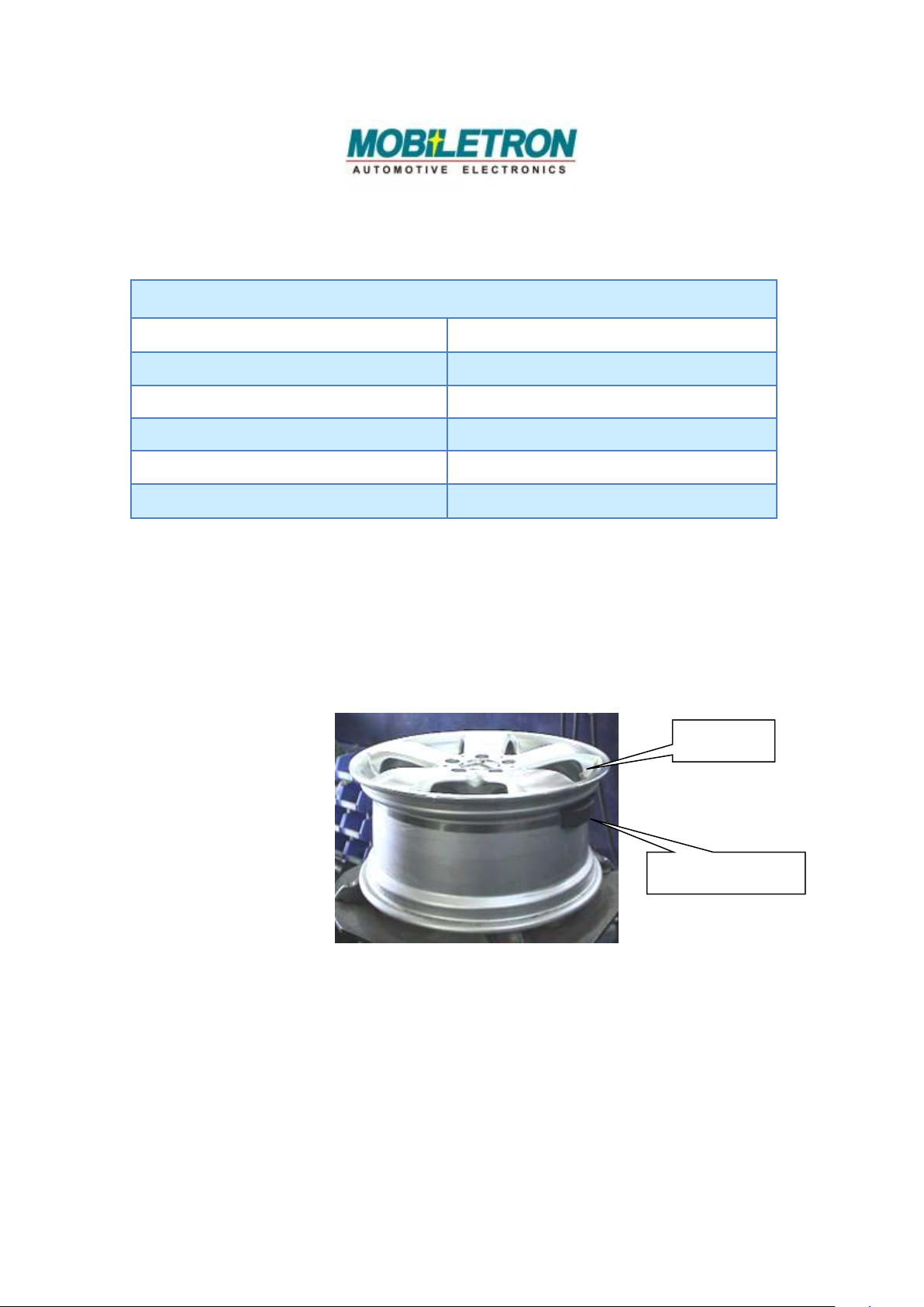
Transmitter
Valve
TPMS_TX
TX026 User's Manual
Mounting the Tire with Transmitter on Wheel Rim
1. Fasten Transmitter on the Wheel Rim
1st. Pass Clamping Strap through Transmitter。
2nd. Position the Transmitter in the lowest area of the
concave center well near the valve。
Note:It is recommended that the location of each transmitter be
recorded to avoid possible damage when tires need to be
removed。
3rd. Attach the Clamping Strap end to the clamp by
advancing the Worm Gear Clamp with a socket driver
or screwdriver ; tighten the Clamping Strap until
secured.。
Page 2
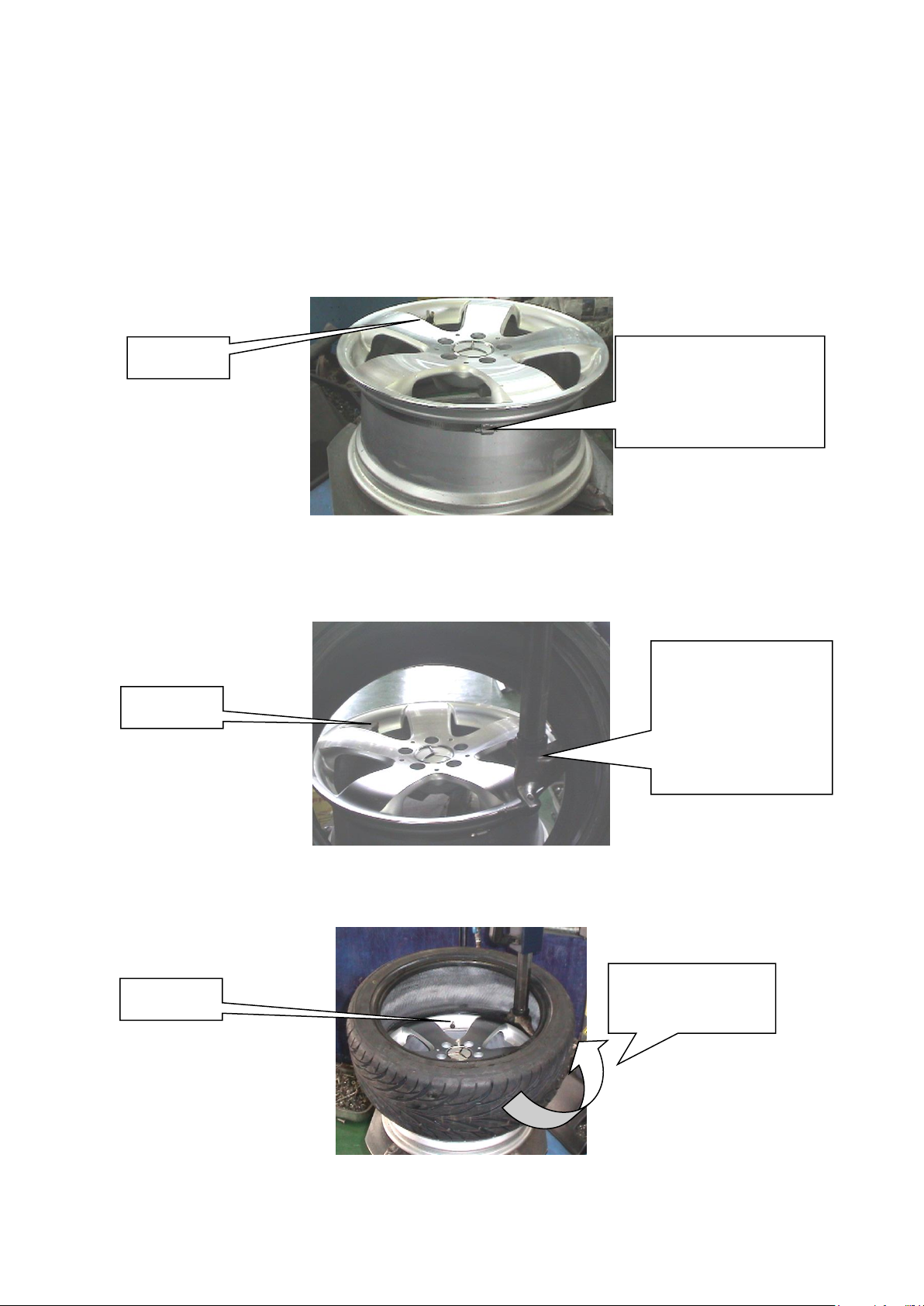
Note:Position Worm Gear Clamp opposite to Transmitter for
Position Worm Gear
Clamp Opposite to
Transmitter
Valve
Valve
Place Tire
Changing
Machine’s Lever to
the Opposite Side
of Valve
Turn in This
Direction Slowly
Valve
better tire rebalancing。
4th. Cut excess Clamping Strap off to approximately one
inch (25mm) from Worm Gear Clamp with a Cutter;
remove burrs from Clamping Strap end。
1. Assemble Tire
2. Assemble Tire
1st. Place tire under Transmitter as shown below。
2nd. Use auto-install machine to install the lower-side of tire
onto rim。
Page 3

3rd. Place the upper-side of tire onto rim。
Tire Changing
Machine’s Lever Has
to Come to a Stop
Before Valve to
Ensure It Won’t Touch
Nearby Transmitter
Valve
Turn in This
Direction Slowly
Valve
Tire Changing
Machine’s Lever
Place Tire Lever to
the Opposite Side of
Tire Changing Lever
(Contrasting to
Valve) to Protect
Nearby Transmitter
Notice:turn slowly by machine to force down the wall of tire。
4th. Install whole tire to the wheel。
4.1 Removing tire with the transmitter Inside
Caution::
The transmitter devices should be removed by a qualified technician。
The removal directions must be followed to ensure that the
transmitters are undamaged。
1. Remove Valve Cap and Deflate Air Completely
Screw valve cap out of valve and let air discharge completely;
remove balancing weight/s;press tire off the safety shoulder
inside and outside。
Page 4

Location of
Transmitter
Within Tire
Location of
Transmitter
Within Tire
Valve
Tire Changing
Machine’s Lever
Valve
Tire Changing
Machine’s Lever
Location of
Transmitter
Within Tire
Valve
Tire Changing
Machine’s Lever
Tire Lever
Caution: In order not to damage the transmitter,Tire Level should be placed in
the opposite side of valve。
2. Removing the tire from the rim
1st. Place tire onto the installation machine;rub soapy
water onto tire bead and rim lip。
2nd. Place the machine Tire Lever on the tire bead and lift
Page 5

tire bead with a manual Tire Lever over the installation
Turn in This
Direction Slowly
Manual Tire Lever
Transmitter
Turn in This
Direction
Slowly
Manual Tire Lever
Tire Changing
Machine’s Lever
Tire Changing
Machine’s Lever
Manual Tire Lever
Location of
Transmitter
Within Tire
head and pull tire away。
3rd. Utilize Manual Tire Lever,simultaneously with Tire
Changing Machine’s Lever,to pull the lower tire bead
away from upper side of wheel。
4th. Remove the Transmitter from the rim。
Page 6

FCC Notices
This device complies with Part 15 of the FCC Rules. Operation is subject to the following two
conditions: (1) this device may not cause harmful interference, and (2) this device must accept
any interference received, including interference that may cause undesired operation.
This equipment has been tested and found to comply with the limits for a Class B digital device,
pursuant to Part 15 of the FCC Rules. These limits are designed to provide reasonable
protection against harmful interference in a residential installation. This equipment generates,
uses and can radiate radio frequency energy and, if not installed and used in accordance with
the instructions, may cause harmful interference to radio communications. However, there is
no guarantee that interference will not occur in a particular installation. If this equipment does
cause harmful interference to radio or television reception, which can be determined by turning
the equipment off and on, the user is encouraged to try to correct the interference by one or
more of the following measures:
--Reorient or relocate the receiving antenna.
--Increase the separation between the equipment and receiver.
--Connect the equipment into an outlet on a circuit different from that to which the receiver is
connected.
--Consult the dealer or an experienced radio/TV technician for help.
CAUTION:
Any changes or modifications not expressly approved by the grantee of this device could void
the user's authority to operate the equipment.
RF exposure warning:
The equipment complies with FCC RF exposure limits set forth for an uncontrolled
environment.
The equipment must not be co-located or operating in conjunction with any other antenna or
transmitter.
This equipment should be installed and operated with minimum distance 20cm between the
radiator and your body. It could be removed.
 Loading...