

mobilerepeater MR Mini GSM 900, MR Mini GSM 1800, MRPowerMAX, MRPowerMAX XT, MR PRO GSM 900 Installation Manual
Page 1
Mobile Repeater Unit 1a Learoyd Rd, New Romney, Kent TN28 8XU,UK
Email: sales@mobilerepeater.co.uk Website: www.mobilerepeater.co.uk
Ph: 0808-234-4257 International: +001-204-452-0903
Mobile Phone Repeater Kit - Installation Guide
Models:
MR Mini GSM 900
MR Mini GSM 1800
MR PRO GSM 900
MR PRO GSM 1800
Page 2

Mobile Repeater Unit 1a Learoyd Rd, New Romney, Kent TN28 8XU,UK
Email: sales@mobilerepeater.co.uk Website: www.mobilerepeater.co.uk
Ph: 0808-234-4257 International: +001-204-452-0903
Sec 1: Installation Procedure
Sec 1-A: Pre-Installation consideration
Before installing the repeater kit you should check the availability of adequate
signal from the service provider outside the premises, which can be confirmed by
making calls from the mobile phone and observing the signal bars on the phone.
If there is adequate signal strength available outside the premises, you can
continue with installation of the kit. If you do not have sufficient signal to place a
call please contact us for an alternative solution.
Sec 1-B: Location of external signal antenna
The external white panel antenna captures the mobile signal from the provider’s
local mast and feeds the input to the repeater unit. The antenna location
therefore is important to overall system performance. Some factors that should
be considered are:
• Line of sight – if possible mount the panel antenna so that it’s face has
clear light of site to the closest mobile base station mast. If you are not
sure where the mast is or in which direction locate the spot outside with
the strongest signal and mount there.
• The external antenna should ideally be mounted on the rooftop in order to
clear as many obstacles as possible. In general, the higher the antenna is
mounted the stronger signal it will capture.
• The cable route from the antenna to the base unit should be free from
sharp bends and kings to avoid damage to the cable. Bends and kinks can
severely impact system performance by reducing the input signal to the
booster.
Page 3

Mobile Repeater Unit 1a Learoyd Rd, New Romney, Kent TN28 8XU,UK
Email: sales@mobilerepeater.co.uk Website: www.mobilerepeater.co.uk
Ph: 0808-234-4257 International: +001-204-452-0903
Sec 1-C: Location of the Mobile Repeater base unit
The following points should be considered in locating the base unit:
• Accessibility to AC power supply for the repeater base
• Flat surface for mounting the base unit
• Locate a cool, dry location away from heat generating appliances or other
equipment
• The repeater unit should be located centrally where coverage is needed.
Sec 2: Installation Procedure
The following points should be used as a guideline for installing your repeater
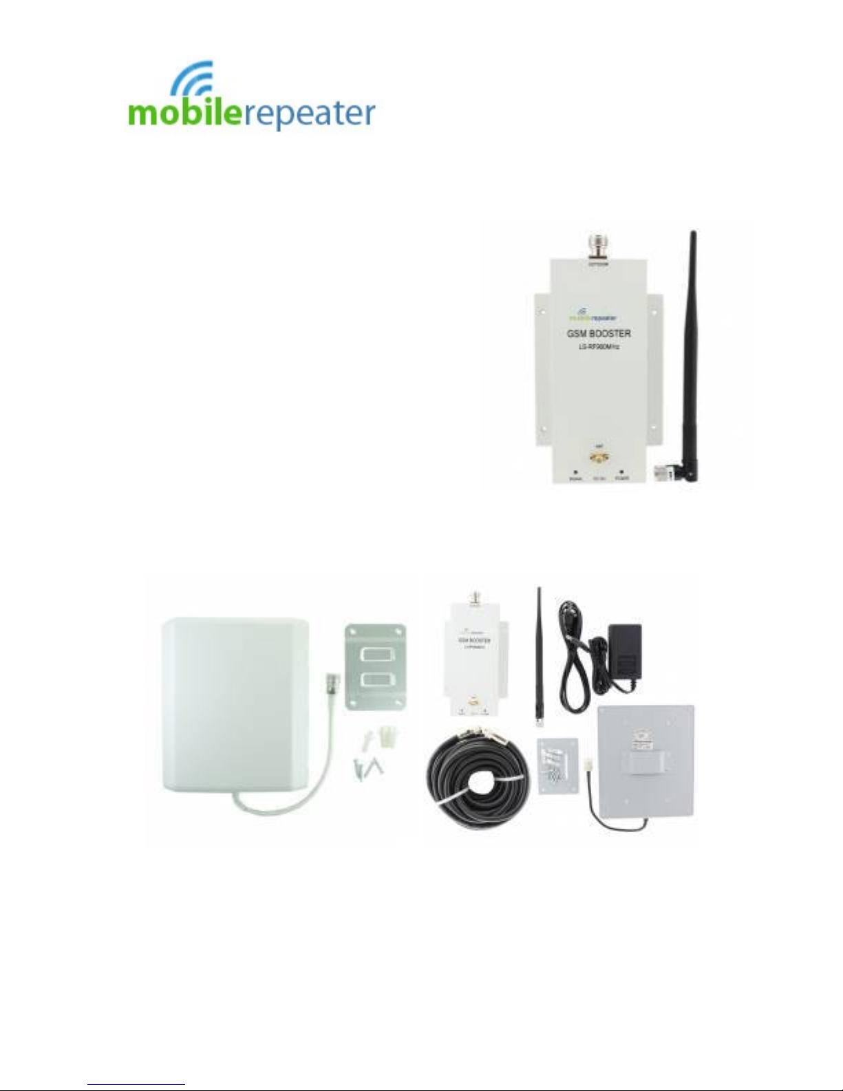
• Unpack the system and identify the external panel antenna, base unit
repeater, indoor omni-directional whip antenna, 10m coaxial cable and
AC/DC power pack.
• Mount the external signal antenna as per points discussed above in Sec
1-B.
• Determine cable route from external antenna to the location of the base
unit discussed in Sec 1-C.
• Provide a firm connection of the coaxial cable with the outdoor antenna
through the connector fixed at the cable end and connect the other side of
the cable to the port on the booster base unit labeled ‘Outdoor’. When
routing cable ensure that the cable is supported and does not sag.
• Connect the indoor whip aerial to the port labeled ‘Indoor’ on the booster
base unit.
Page 4

Mobile Repeater Unit 1a Learoyd Rd, New Romney, Kent TN28 8XU,UK
Email: sales@mobilerepeater.co.uk Website: www.mobilerepeater.co.uk
Ph: 0808-234-4257 International: +001-204-452-0903
Sec 3: Commissioning
• Plug in the AC/DC Power Adapter power cord to AC mains and other side
DC plug shall be inserted in DC socket on the repeater base unit.
• When power is supplied the red indicator light labeled “Power” should
glow.
• If there is a sufficient signal level at the location of the outdoor panel
antenna, the light labeled “Signal” should glow green. If this light remains
off it means that either:
o There is an insufficient signal level at the external antenna. If this
happens you should attempt to re-mount or re-orient the external
antenna go achieve a higher signal level. The best location can be
found my monitoring the ‘bars’ level on your phone.
o There may be interference between the outdoor panel antenna and
the indoor whip antenna attached to the booster if the two items are
located too close to each other. This feedback creates system
oscillation, feedback and reduces the signal input signal level to the
base unit. You should try and maximize the separation both
vertically and horizontally between the antennas. Note it is
important to have a physical barrier between the outside antenna
and indoor whip antenna (i.e. roof, wall etc.) which helps isolate the
two.
Page 5

Mobile Repeater Unit 1a Learoyd Rd, New Romney, Kent TN28 8XU,UK
Email: sales@mobilerepeater.co.uk Website: www.mobilerepeater.co.uk
Ph: 0808-234-4257 International: +001-204-452-0903
In regards to the isolation between antennas the following may be considered:
• The optimal location for the outdoor antenna should be high above the
rooftop and exterior to the building.
• Do not mount the base unit repeater near a window or near the external
aerial
• Mount the outdoor antenna as high as physically possible to the exterior of
the building for maximum vertical separation between antennas and
pointing away from the building towards the mobile mast site.
• Install the antennas taking advantage of any existing building structure
such as brick walls, metal roofs or multiple wall structures for providing
additional attenuation to the signals directly reaching from one antenna to
another antenna.
Thank you for choosing Mobile Repeater. For customer support or sales
enquiries please contact our location below.
MobileRepeter.co.uk
C/O Integer Group Ltd
The Distribution Centre
Learoyd road
New Romney,Kent
TN28 8XU
Toll Free: 08082 344257
Email: sales@mobilerepeater.co.uk
 Loading...