

Page 1
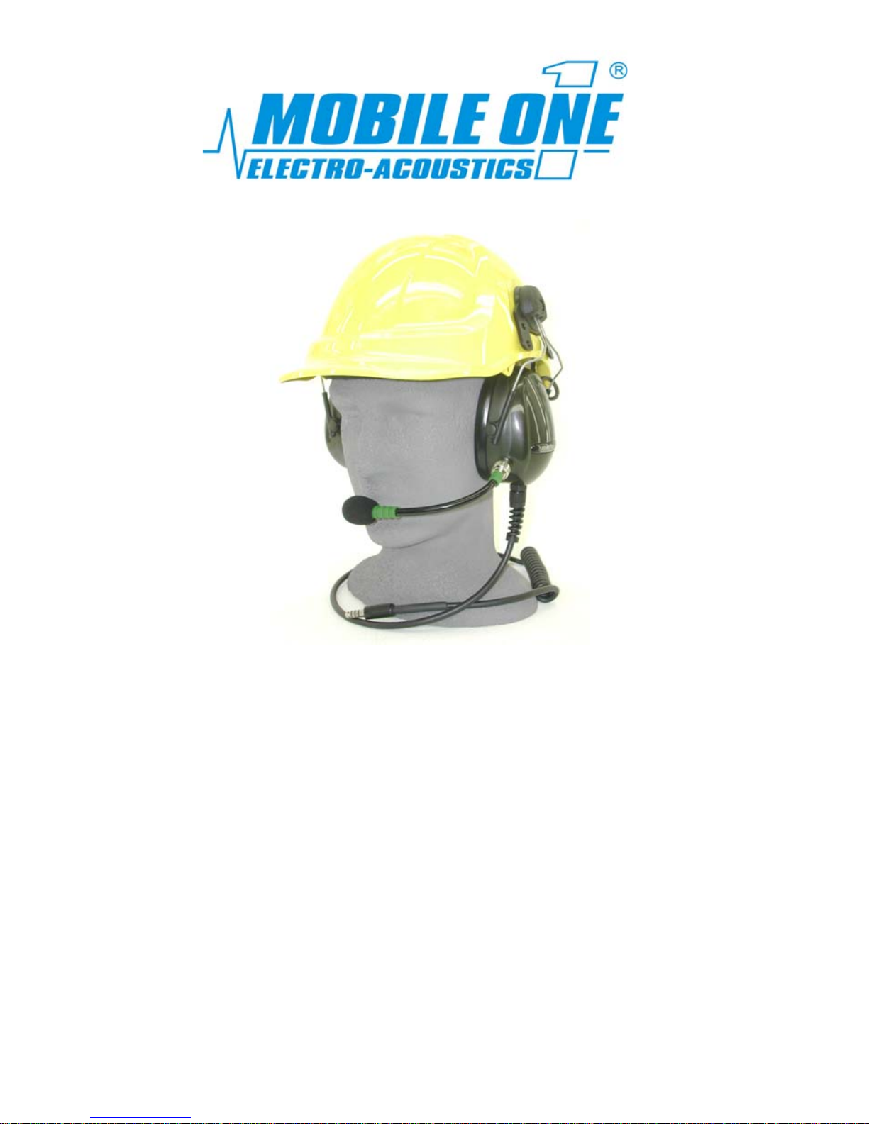
HEADSET INSTRUCTIONS
AND
USER GUIDE
HSP-5 & 7 SERIES
t
Thank you for choosing a quality communica ions Headset
from Mobile One Australia. This Headset has been designed
and developed to maximise comfort, to provide superior
electronic communications and to ensure excellent hearing
protection within environments of high ambient noise.
Page 2

2
INDEX
CERTIFICATION DATA 2
WARNINGS 2
FITTING INSTRUCTIONS 3 - 8
CARE & MAINTENANCE 8 - 9
PARTS REPLACEMENT 9 - 10
NOISE EXPOSURES 11
WARRANTY 12
CONTACT DETAILS 12
CERTIFICATION DATA
Mobile One headsets are approved to comply with AS1270 -2002, Acoustics Hearing Protectors. NOTE: The headsets must be selected, used and
maintained according to AS 1269.
These instructions must be followed if the headset is expected to perform
as indicated by the SLC80 rating in the chart below:
MODEL
No.
SLC80
RATING
CLAMP
FORCE
MASS
FREQUENCY
Hz
125 250 500 1000 2000 4000 8000
HSP-5
28
11
400
MEAN
STD. DEVTN.
MEAN – STD. DEV.
15.7
4.7
11.0
19.5
3.2
16.3
27.6
3.7
23.9
30.6
3.9
26.7
35.0
3.7
31.3
38.3
3.6
34.7
46.3
4.7
41.6
HSP-7
28
11
376
MEAN
STD. DEVTN.
MEAN – STD. DEV.
15.4
4.4
11.0
19.5
2.7
16.8
26.3
2.7
23.6
30.3
3.8
26.5
35.3
2.8
32.5
37.9
4.4
33.5
40.2
4.5
35.7
According to the Class rating system: The HSP-5 Headset is a Class 5
The HSP-7 Headset is a Class 5
WARNINGS
This headset will only provide the hearing protection as indicated by the SLC80 rating
when it is maintained in good working or der and fitted correctly. Other factors affecting
the noise attenuation characteristics of the headset are items which affect the seal
between the Ear Cushion and the head e.g. thick framed glasses, protective clothing
such as balaclavas, thick beards, etc.
It is vitally important that you give consideration to the sound output produced by the
earphones in the headset itself. You must ensure that the volume setting of the radio, or
other connected device, is adjusted to a safe listening level as there are no output
limiting devices included within the electronic circuitr y of the headset.
For correct care of this Headset, you must refer to the care and maintenance
Instructions on page 8.
Page 3
FITTING INSTRUCTIONS
The purpose of this Headset is to:
1. Protect your hearing
2. Provide electronic communications
Correct fitment of the Headset to your head is vital for maximum
hearing protection and to optimise communications ability.
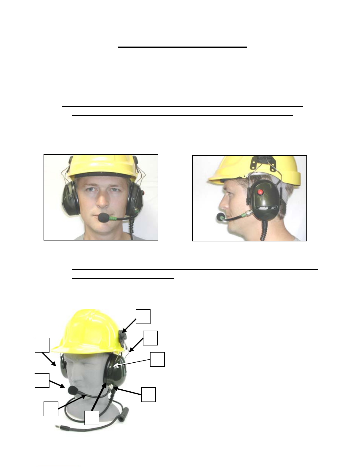
A CORRECTLY FITTED HEADSET
Figure A Figure B
NB: The Headset Ear Cups must be fitted over your ears covering and
enclosing them completely
PARTS OF A HEADSET
1. Hardhat Adaptor Plate
3
2. Ear Cup Arms
3. Plastic Slide
4. Ear Cushion
5. Ear Cup
6. Microphone (Mic.) attachment
socket
7. Mic. Boom
8. Mic. Head
Figure C
1
2
3
5
8
7
6
4
Page 4
STEP BY STEP USER GUIDE
NOTE: The Headset is intended to be worn with the microphone
and cable on the wearer’s left hand side.
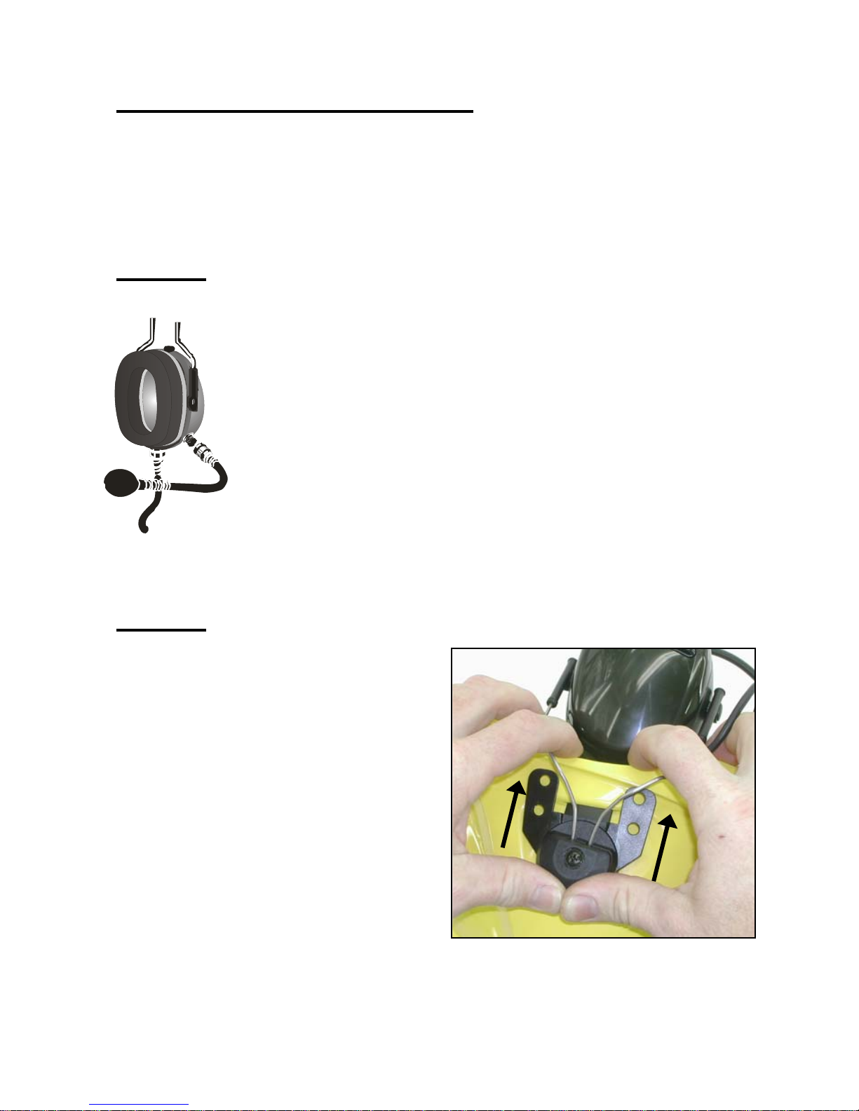
STEP 1 Fitting the Mic. Boom
Fit th d on
the
Rot
Cu
e Microphone Boom assembly to the mounting socket locate
Left Side Ear Cup (cable side).
ate the collar clockwise whilst screwing onto the socket on the Ear
p. Firmly finger-tighten only.
Partly bend the boom to where you estimate your mouth will be,
ensuring the Yellow Dot is facing towards the mouth.
Figure 1.0
STEP 2 Fitting the Headset onto the Hardhat (Typical)
Insert the Hardhat Adaptor Plate for each
of The two Ear Cups into the slot provided
of each side of the Hardhat. This can be
easily done by using your fore finger and
index finger as an anchor and firmly
pushing in with your thumb until the
Adaptor locks into place. Check that they
are correctly locked in by trying to pull
them out again. The adaptors should
remain firmly in place. Ensure that Ear
Cup with Mic. is fitted to the left side of
hardhat.
Figure 2.0
4
Page 5
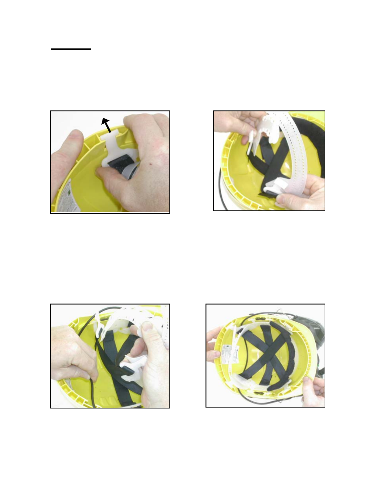
STEP 3 Placing Inter-Cup Cable inside the Hardhat
a) With your thumb as an anchor point, use your fore finger and inde x finger
to push out and remove the two rear clips that support the harness within
the Hardhat. See figures 3.1 & 3.2.
Figure 3.1 Figure 3.2
b) Place Inter-Cup Cable inside Hardhat as shown in figure 3.3. Ensure the
cable is an even length at both sides, see item (b). Replac e the rear two
clips of the harness into their mounting points as shown in figure 3.4 by
reversing process a) above. NB. This cable is intentionally long to cater for
different mounting alternatives
5
Figure 3.3 Figure 3.4
Page 6
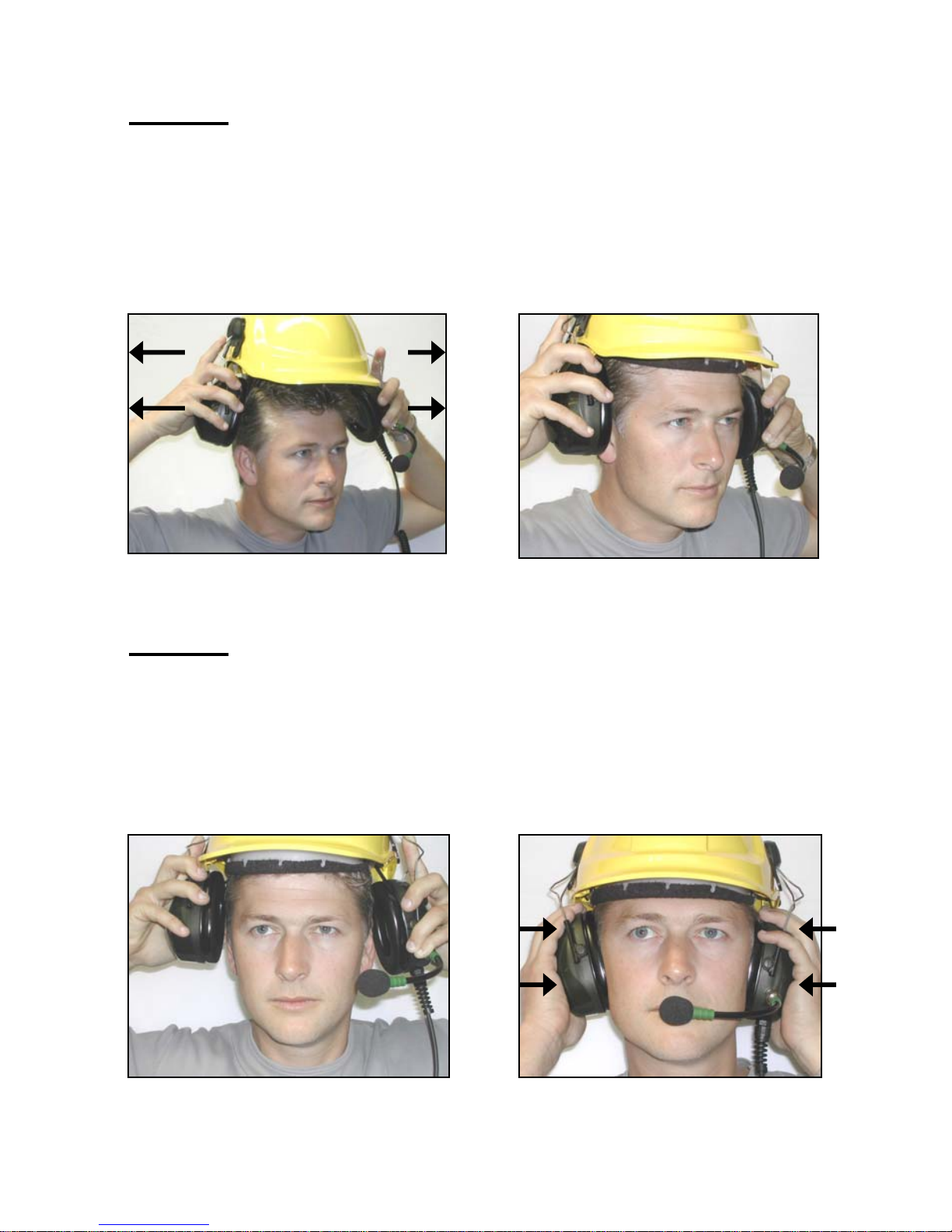
STEP 4 Putting on Hardhat and Headset
The Ear Cups can be ‘clicked’ into two positions when mounted onto a Hardhat:
1. Disengaged – Cups positioned outward away from head (figure 4.1 & 4.2).
2. Engaged – Cups positioned inwards against the head (figure 5.2 bottom right)
To put on the Hardhat with Headset, first click both Ear Cups outward to the Disengaged
position (figure 4.1). Then simply place the Hardhat on your head with the Mic. on the left
side. See Figure 4.2. (N.B. Also check hardhat manufacturer instructions for fitting)
6
Figure 4.1 Figure 4.2
STEP 5 Engaging Ear Cups
a) To engage, place one hand on each of the Ear Cups and, together, simply
push firmly inwards towards the head. The Ear Cups will both click into place
against your head.
b)
Continue to push Ear Cups firmly against head and hold for 2 to 3 seconds.
This expels excess air from the Ear Cushions making them more comfortable
and helping to provide better hearing protection. See figure 5.1 and 5.2.
Figure 5.1 Figure 5.2
Page 7
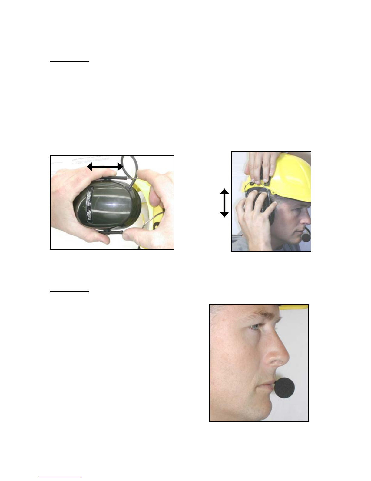
STEP 6 Adjusting Ear Cups for comfort
a) Figure 6.1 below illustrates how the black Adjusting Slides can be moved up or
down on the Headband. This allows you to adjust the position of the Ear Cup to
provide better comfort and a more efficient seal on the head to keep out noise.
b) Utilising the up / down adjusting slides, with one hand on the Hardhat (as shown
in Figure 6.2), move the Ear Cups up or down so that they completely cover your
ears and fit comfortably. Try to make similar adjustments for each Ear Cup so that
they sit evenly on both sides. Repeat procedure in Part b) of Step 5 previo us page,
of pushing and holding Ear Cups to improve comfort and hearing protection.
Figure 6.1 Figure 6.2
STEP 7 Adjusting the Mic. For maximum clarity
7
(7a) ADJUSTING MIC. DISTANCE
Microphone must be positioned
as close to the lips as is comfortable.
This provides better voice clarity
See Figure 7.1.
Maximum Distance
From lips = 5 mm
Figure 7.1
Page 8
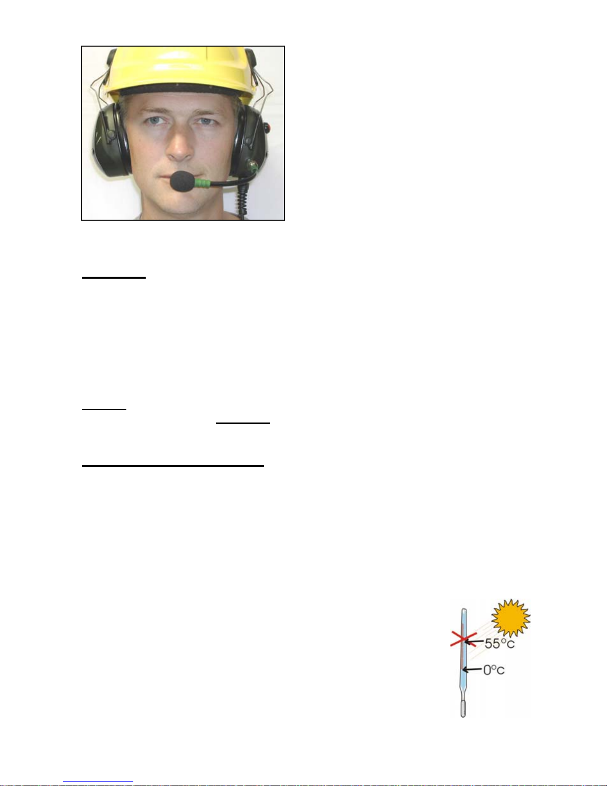
(7b) ADJUSTING MIC. POSITION
Adjust windsock (Microphone) to be
directly in the centre of the mouth
opening. Ensure that the Yellow Dot
is facing toward your mouth.
See figure 7.2
Figure 7.2
STEP 8 Checking electronic operation
Check Earphones (speakers)
You should hear sound from your radio i n both Ear Cups. If this is not the
case, check the connection to the communications device or that the
device is operating properly.
Check Microphone
Check that the speech you are attempting to transmit is reaching the
intended person clearly.
Caution: Do not set the volume level of the radio, or other connected device, too
high! See paragraph 2 of
Warnings on page 2
CARE & MAINTENANCE
We recommend that your headset be cleaned regularly, by wiping with a damp
sponge containing mild soap and water. Pay sp ecial attention to the Ear Cushions
to ensure removal of perspiration and skin oils which can reduce the service life of
the Cushions. These areas of the Headset that come into contact with the wearer’s
skin should also be regularly disinfected using isopropyl alcohol wipes.
When cleaning DO NOT allo w water to enter the Ear Cup as semblies or an y part of
the Microphone Assembly
. UNDER NO CIRCUMSTANCES SHOULD YOU
IMMERSE THE HEADSET IN WATER.
IMPORTANT: This Headset should not be stored in direct
sunlight or temperatures above 55 degrees C. as disto rtion of
the Ear Cushions may occur.
8
Page 9

9
To maintain the noise attenuation properties of the Heads et, the Ear Cushions (see
Figure 8.0, item 4) should be replaced every six months and the inner foam and
spacer assembly (see Figure 8.0 , item 3) every twelve months. More frequent
replacement of these items may be required if the Headset is being used under
extreme conditions. Inspect the headset regularly for signs of damage or wear.
PARTS REPLACEMENT (See items 1 – 4 pictured in Figure 8.0)
To remove and replace MIC. BOOM (item 1) see the “F itting Instructions - Step 1”
and simply reverse the process by unscrewing, counter clockwise, the knurled nu t
at the base of the MIC. BOOM.
The EAR CUSHIONS (item 4) are removed by placing one or t wo fingers inside the
Ear Cup and under the Cushion’s rigid plastic plate. Pull the Ear Cushion a way from
the cup. The new Cushions just clip back into place under the lip around the
circumference of the Ear Cup opening. Ensure the Ear Cushion plate has seated
and clipped-in properly before use.
The INNER FOAM ASSEMBLY (item 3) also supports the earphone and care
should be taken not to damage the wiring. With the Ear Cushions removed,
carefully take out the foam wafer and pull apart the two bottom layers where the
wires enter. Carefully remove the Earphone. Place the Earphone into the n e w foam,
remove paper cover and press both layers together. Install foam back in cup and
replace Ear Cushion.
The WIND SOCK (item 2) is the black foam cover on the Mic. Head at the end of
the Mic. Boom. To remove, simply pull the Wind S ock off the end of the Mic. Boom
and gently push the replacement Wind Sock over the Mic. Head again.
Page 10
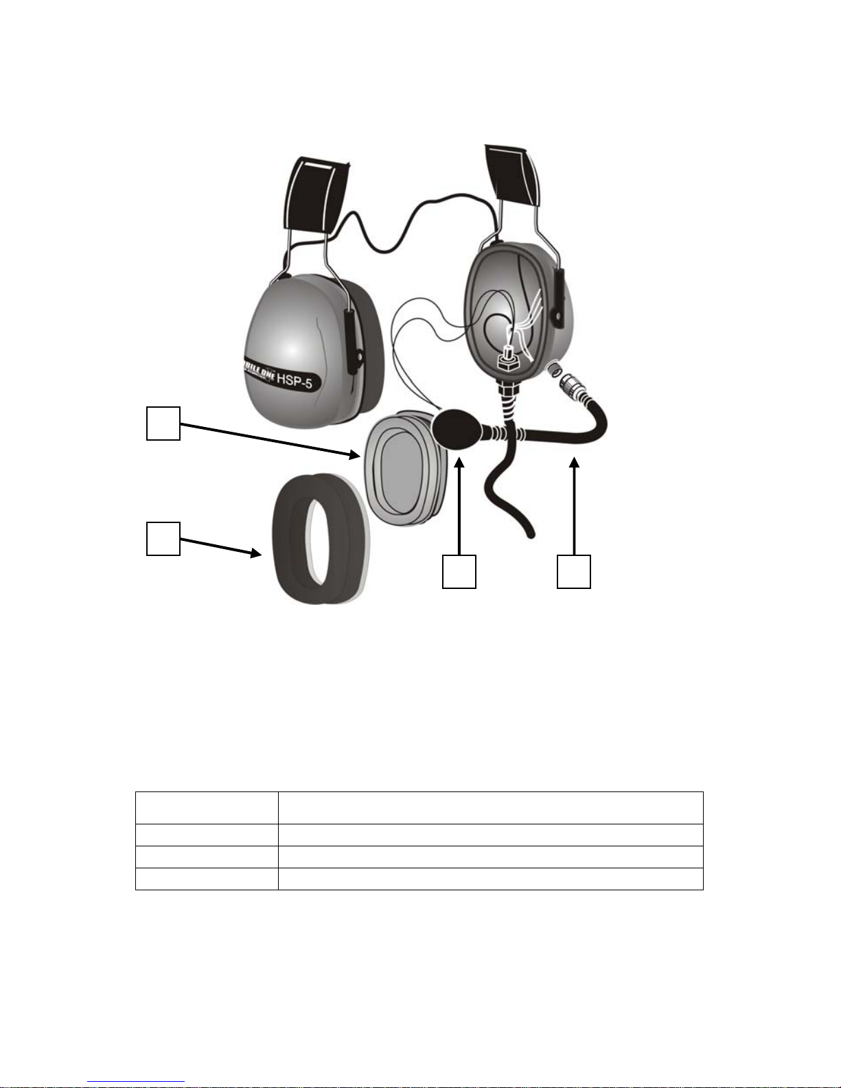
HEADSET PARTS – EXPLODED VIEW
4
3
2 1
Figure 9.0
REPLACEMENT PARTS LIST
Order Code Description
HSP-FCK
Hygiene Kit (includes items 3 & 4)
MB102
Microphone Boom (includes items 1 & 2)
WSS2
Replacement Wind Sock for Mic. Head (item 2)
10
Page 11
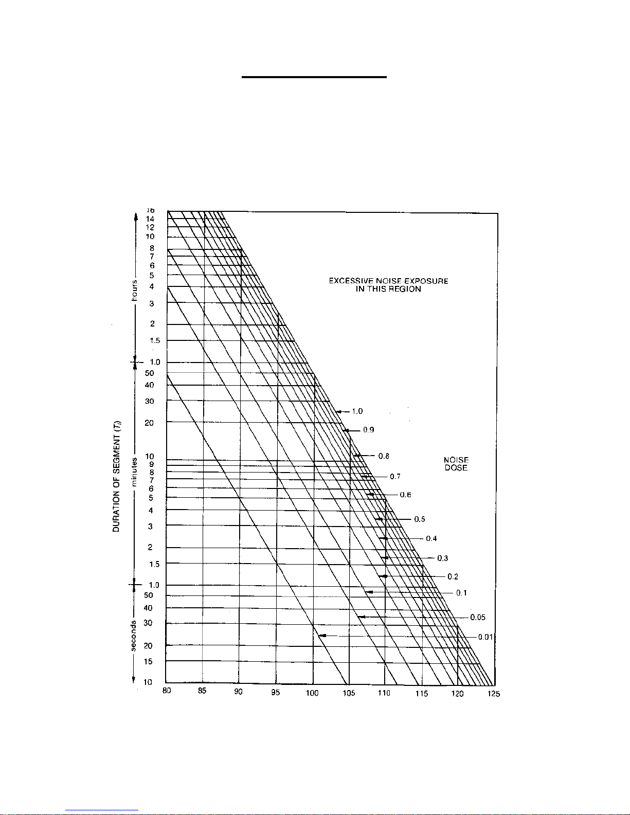
NOISE EXPOSURES
There is considerable medical research data now available which clearly demonstrates a
link between the loss of hearing in humans as a result of exposure to noise. The factors
which contribute to this loss of hearing are many and complex, and as the Headset user
you should discuss your requirements with suitably qualified professionals to ensure that
the headset you have selected is suitable for the type (frequencies) of noise & level of
noise you may encounter as well as the period of exposure. The chart below should be
read in conjunction with AS/NZ standard 1269.
Noise Exposure Chart
Noise Level - Continuous (L
Aeq , T, i
), dB(A)
11
Page 12

12
“NO WORRIES”
AUSTRALIAN PRODUCT WARRANTY
Any MOBILE ONE product that fails due to manufacturing defects will be repaired
or replaced as follows:
General Aviation & Helicopter headsets-
Three (3) full years from date of purchase.
Intercoms, Headsets other than above & Accessories-
One (1) full year from date of purchase.
NOTE: This warranty excludes Wind Socks, Ear Cushions & Foam Assemblies.
Should you need to contact us at the factory, our details are:
Mobile One Australia Pty Limited
Electro-Acoustic Engineering Division
Camden Airport, Camden NSW.
AUSTRALIA
Phone 02 4655 6677
Fax 02 4655 6600
INTERNATIONAL
Phone +61 2 4655 6677
Fax +61 2 4655 6600
www.mobileone.com.au
Mobile one is proudly an Australian owned company. Our Electronic
Hearing Protection and Communication products are designed,
developed and manufactured in Australia.
Copyright: Mobile One Australia Pty Ltd. Version 5, Apr 2008
 Loading...