

Page 1
User Guide (en)
Date: 03/2021
Revision: v.1.4
Page 2

Copyright and disclaimer
All rights reserved. No parts of this document may be reproduced in any form without the
express written permission of Mobile Industrial Robots A/S (MiR). MiR makes no warranties,
expressed or implied, in respect of this document or its contents. In addition, the contents of
the document are subject to change without prior notice. Every precaution has been taken in
the preparation of this document. Nevertheless, MiR assumes no responsibility for errors or
omissions or any damages resulting from the use of the information contained.
Copyright © 2020-2021 by Mobile Industrial Robots A/S.
Contact the manufacturer:
Mobile Industrial Robots A/S
Emil Neckelmanns Vej 15F
DK-5220 Odense SØ
www.mobile-industrial-robots.com
Phone: +45 20 377 577
Email: support@mir-robots.com
CVR: 35251235
MiR250 Shelf Carrier User Guide (en) 03/2021 - v.1.4 ©Copyright 2021: Mobile IndustrialRobots A/S. 2
Page 3

Table of contents
1. About this document 8
1.1 Where to find more information 8
1.2 Version history 9
2. Product presentation 10
2.1 Main features of MiR250 Shelf Carrier 11
2.2 External parts 13
2.3 Internal parts 21
2.4 How MiR Shelf Carrier 250 works 30
3. Warranty 31
4. Safety 32
4.1 Safety message types 32
4.2 General safety precautions 33
4.3 Intended use 38
4.4 Users 39
4.5 Foreseeable misuse 40
4.6 Warning label 41
4.7 Residual risks 41
5. Accessing the internal parts 43
5.1 Front compartment 44
5.2 Rear compartment 45
5.3 Side compartments 46
5.4 MiR Shelf Carrier 250 47
6. Getting started 48
MiR250 Shelf Carrier User Guide (en) 03/2021 - v.1.4 ©Copyright 2021: Mobile IndustrialRobots A/S. 3
Page 4

6.1 In the box 48
6.2 Unpacking MiR250 Shelf Carrier 50
6.3 Connecting the battery 53
6.4 Powering up the robot 55
6.5 Connecting to the robot interface 58
6.6 Driving the robot in Manual mode 59
6.7 Moving the robot by hand 62
6.8 Checking the hardware status 64
6.9 Mounting the nameplate 65
6.10 Enable the MiR250 Shelf Carrier feature 67
6.11 Testing the top module 69
6.12 Shutting down the robot 71
7. Battery and charging 73
7.1 Charging the robot 73
7.2 Disconnecting the battery 74
7.3 Enabling fast swap 75
7.4 Swapping out the lithium-ion battery 77
7.5 Battery storage 79
7.6 Battery disposal 80
8. IT security 82
8.1 Managing users and passwords 82
8.2 Software security patches 82
9. Navigation and control system 84
9.1 System overview 84
MiR250 Shelf Carrier User Guide (en) 03/2021 - v.1.4 ©Copyright 2021: Mobile IndustrialRobots A/S. 4
Page 5

9.2 User input 86
9.3 Global planner 86
9.4 Local planner 88
9.5 Obstacle detection 89
9.6 Localization 94
9.7 Motor controller and motors 97
9.8 Brakes 97
10. Safety system 99
10.1 System overview 99
10.2 Personnel detection 104
10.3 Overspeed avoidance 108
10.4 Stability 109
10.5 Emergency stop buttons 109
10.6 MiR Shelf Carrier 250 safety functions 110
10.7 Safety stop 112
10.8 Light indicators and speakers 113
11. Commissioning 117
11.1 Analysis of the work environment 117
11.2 Risk assessment 119
11.3 Shelf specifications 120
11.4 Creating and configuring maps 124
11.5 Markers 135
11.6 Positions 138
11.7 Creating missions 139
MiR250 Shelf Carrier User Guide (en) 03/2021 - v.1.4 ©Copyright 2021: Mobile IndustrialRobots A/S. 5
Page 6

11.8 Creating a footprint 142
11.9 Using operating hazard zones 145
11.10 Making a brake test 150
11.11 Creating user groups and users 151
11.12 Creating dashboards 154
11.13 Updating MiR250 Shelf Carrier software 156
11.14 Creating backups 157
11.15 System settings 157
12. Usage 166
12.1 Creating markers 166
12.2 Creating positions 172
12.3 Creating a marker type 174
12.4 Creating the mission Prompt user 177
12.5 Creating the mission Try/Catch 182
12.6 Creating the mission Variable docking 188
12.7 Creating the mission 80 cm doorway 196
12.8 Creating the mission Pick up and place shelf 203
12.9 Creating the mission Place shelf at VL-marker 208
12.10 Testing a mission 213
13. Unmounting the top module 215
14. Maintenance 220
14.1 Regular weekly checks and maintenance tasks 220
14.2 Regular checks and replacements 222
14.3 Battery maintenance 224
MiR250 Shelf Carrier User Guide (en) 03/2021 - v.1.4 ©Copyright 2021: Mobile IndustrialRobots A/S. 6
Page 7

15. Packing for transportation 226
15.1 Original packaging 226
15.2 Packing the robot for transportation 227
15.3 Battery 227
16. Disposal of robot 228
17. Payload distribution 229
17.1 Side view 230
17.2 Front view 232
17.3 Top view 234
18. Interface specifications 236
18.1 Left side interfaces 236
18.2 Right side interfaces 238
19. Error handling 243
19.1 Software errors 243
19.2 Hardware errors 244
MiR250 Shelf Carrier User Guide (en) 03/2021 - v.1.4 ©Copyright 2021: Mobile IndustrialRobots A/S. 7
Page 8
1. About this document
1. About this document
This user guide explains how to set up and start operating your MiR250 Shelf Carrier robot
and provides examples of simple missions you can expand to your purposes. This guide also
contains information regarding the external and internal components of MiR250 Shelf
Carrier along with instructions for proper maintenance of the robot. You will also find
information regarding safety and specifications needed to commission a safe MiR250 Shelf
Carrier robot application.
NOTICE
Save this manual. It contains important safety and operating instructions.
1.1 Where to find more information
At the MiR website, you can find the following resources under the Manuals tab on each
product page:
• Quick starts describe how you start operating MiR robots quickly. It comes in print in the
box with the robots. Quick starts are available in multiple languages.
• User guides provide all the information you need to operate and maintain MiR robots and
how to set up and use top modules and accessories, such as charging stations, hooks, shelf
lifts, and pallet lifts. User guides are available in multiple languages.
• Commissioning guides describe how to commission your robot safely and prepare it to
operate in the workplace.
• Operating guides describe how to set up and use MiR accessories or supported functions
that are mainly hardware-based, such as charging stations and shelf functions.
• Getting started guides describe how to set up MiR accessories that are mainly software-
based, such as MiR Fleet.
• Reference guides contain descriptions of all the elements of the robot interface and MiR
Fleet interface. Reference guides are available in multiple languages.
• Best practice guides specify how much space MiR robots need to execute common
maneuvers.
• REST API references for MiR robots, MiR hooks, and MiR Fleet. HTTP requests can be
used to control robots, hooks, and MiR Fleet.
• MiR network and WiFi guide specifies the performance requirements of your network
and how you must configure it for MiR robots and MiR Fleet to operate successfully.
MiR250 Shelf Carrier User Guide (en) 03/2021 - v.1.4 ©Copyright 2021: Mobile IndustrialRobots A/S. 8
Page 9
1. About this document
1.2 Version history
This table shows current and previous versions of this document.
MiR250 Shelf Carrier
Revision Release date Description HW
1.0 2020-06-26 First edition 1.0
1.1 2020-07-01 General improvements throughout the
document.
1.2 2020-07-08 Update section: Operating hazard zones
General improvements throughout the
document.
1.3 2020-11-30 Added sections: Warranty, Markers, and
Positions.
Updated section: Battery storage with Power
save mode and Deep sleep mode.
General improvements throughout the
document.
1.4 2021-03-31 Added sections: Enabling fast swap and
Swapping out the lithium-ion battery.
General improvements throughout the
document.
1.0
1.0
1.0
1.0
MiR250 Shelf Carrier User Guide (en) 03/2021 - v.1.4 ©Copyright 2021: Mobile IndustrialRobots A/S. 9
Page 10
2. Product presentation
2. Product presentation
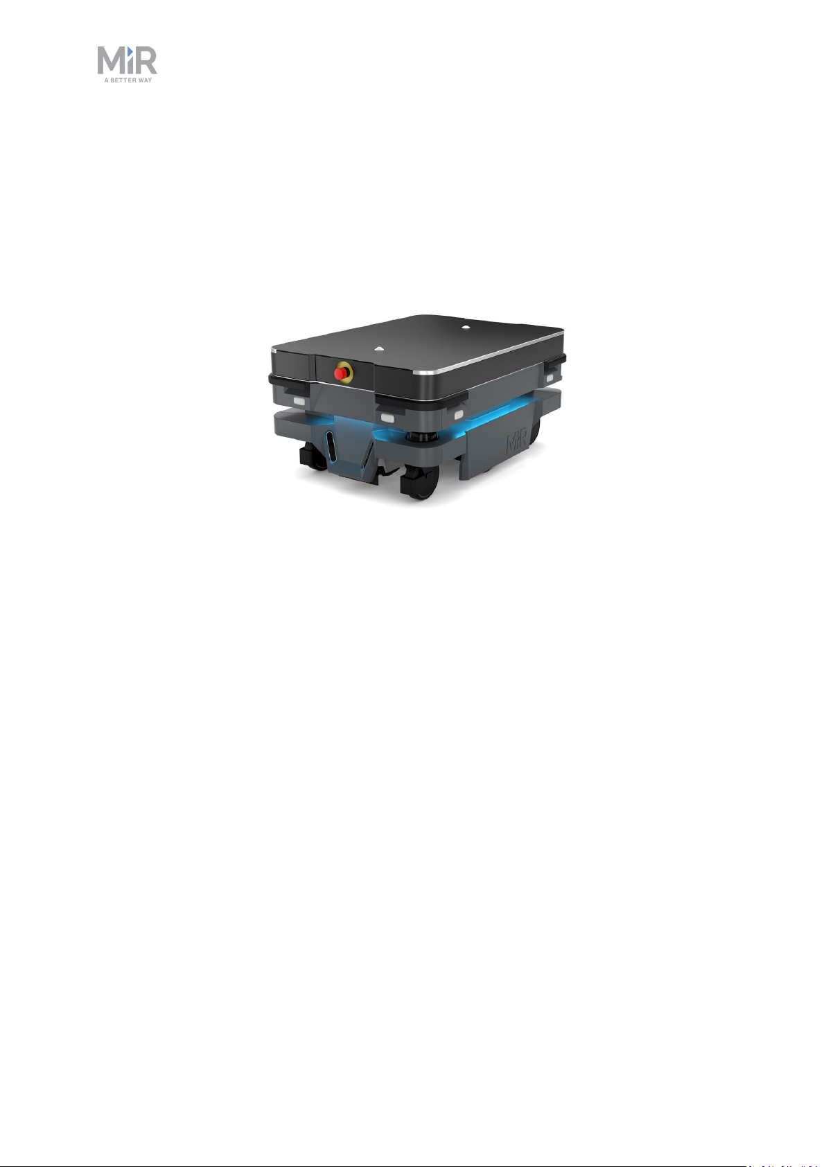
MiR250 Shelf Carrier is an autonomous mobile robot with a top module mounted to it. It is
designed to transport wheeled shelves indoors within production facilities, warehouses, and
other industrial locations where access to the public is restricted.
Users operate MiR250 Shelf Carrier via a web-based user interface, which is accessed
through a browser on a PC, smartphone, or tablet. Each robot has its own network—see
Connecting to the robot interface on page58. The robot can be set up to run a fixed route,
be called on demand, or perform more complex missions.
The robot interface of MiR250 Shelf Carrier can be accessed via Google Chrome, Google
Chromium, Apple Safari, Mozilla Firefox, and Microsoft Edge browsers.
The robot uses a map of its work area to navigate and can move to any position on the
map—see Navigation and control system on page84. The map can be created or imported
the first time the robot is used. While operating, the robot avoids obstacles that are not
mapped, like people and furniture.
MiR250 Shelf Carrier is available both in an ESD approved version, which is black, and a nonESD approved version, which is gray.
MiR250 Shelf Carrier transports shelves that are designed according to the specifications in
Shelf specifications on page120. To ensure that the robot has enough traction to transport a
total payload of up to 300 kg, a traction kit is installed within the robot.
MiR250 Shelf Carrier User Guide (en) 03/2021 - v.1.4 ©Copyright 2021: Mobile IndustrialRobots A/S. 10
Page 11

2. Product presentation
The total payload includes both the weight of the shelf and the load on the
shelf.
Specifications for MiR250 Shelf Carrier are available on the MiR website.
2.1 Main features of MiR250 Shelf Carrier
The main features of MiR250 Shelf Carrier are:
• Driving in a populated workspace
The robot is designed to operate among people and maneuvers safely and efficiently in
highly dynamic environments.
• Overall route planning and local adjustments
The robot navigates autonomously to find the most efficient paths to its destinations. The
robot adjusts the path when it encounters obstacles that are not on the map, like
personnel and vehicles.
• Efficient transportation of shelves
The robot is designed to automate transportation of loaded shelves with a weight of up to
300 kg.
• Sound and light signals
The robot continuously signals with light and sounds, indicating where it will drive and its
current status, for example, waiting for a mission, driving to a destination, or destination
reached.
• User-friendly and flexible
The web-based user interface, accessed from a PC, tablet, or smartphone, gives easy
access to operation and monitoring of the robot and can be programmed without any
prior experience. Different user group levels and tailored dashboards can be set up to suit
different users.
• Alert for 'lost'
If the robot enters a situation where it is unable to find a path to its destination, it stops,
turns on the yellow-purple running error light, and a custom defined Try/Catch action
may be used to alert personnel or take other actions—see Creating the mission Try/Catch
on page182.
MiR250 Shelf Carrier User Guide (en) 03/2021 - v.1.4 ©Copyright 2021: Mobile IndustrialRobots A/S. 11
Page 12

2. Product presentation
• Automatic deceleration for objects
The built-in sensors ensure that the robot is slowed down when obstacles are detected in
front of it.
• Internal map
The robot can either use a floor plan from a CAD drawing, or a map can be created by
manually driving the robot around the entire site in which the robot is going to operate.
When the robot is mapping, the robot’s sensors detect walls, doors, furniture, and other
obstacles, and the robot then creates a map based on these input. After you've finished
mapping, you can add positions and other features in the map editor—see Creating and
configuring maps on page124.
MiR250 Shelf Carrier User Guide (en) 03/2021 - v.1.4 ©Copyright 2021: Mobile IndustrialRobots A/S. 12
Page 13
2. Product presentation
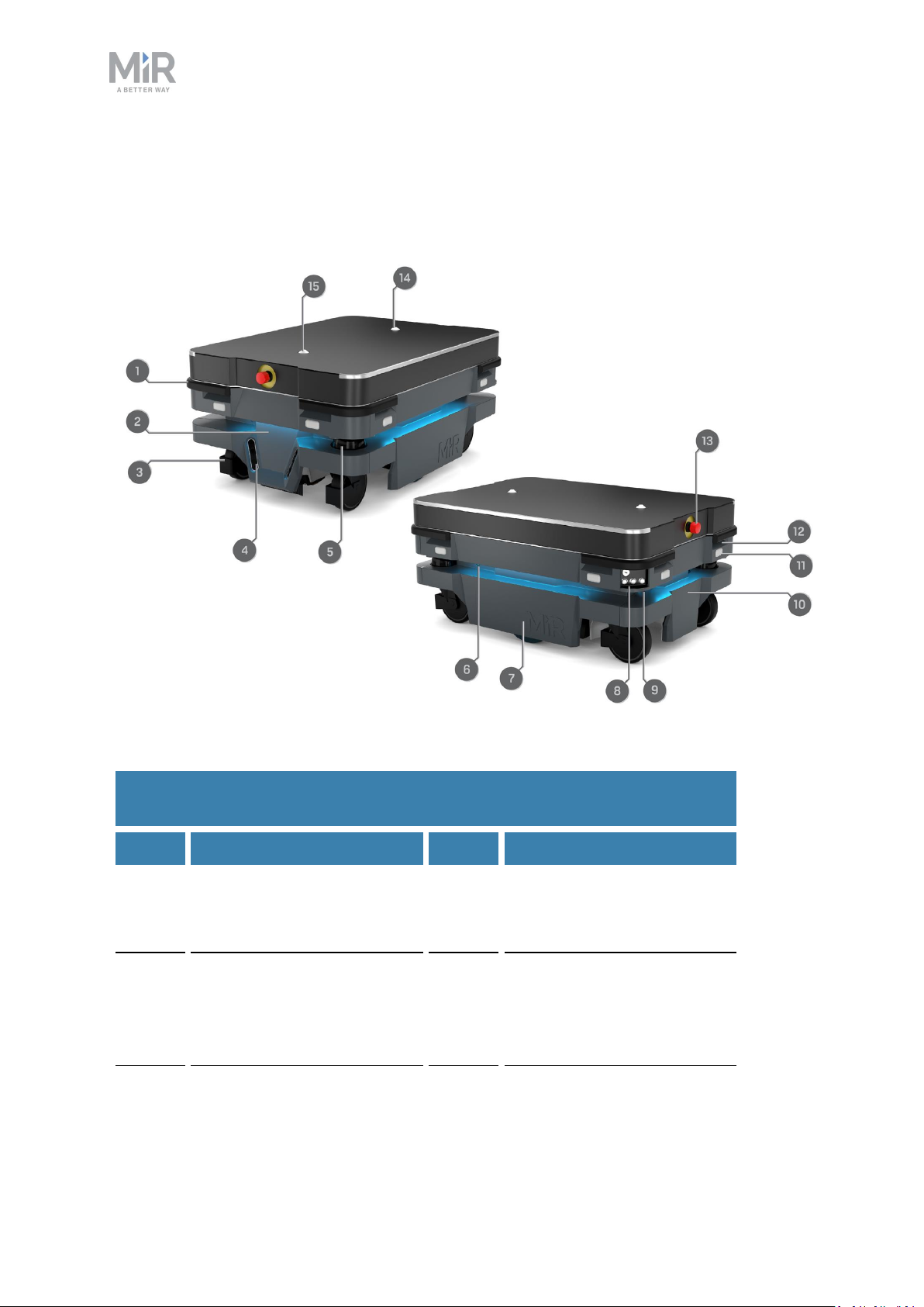
2.2 External parts
This section presents the parts of MiR250 Shelf Carrier that are visible on the outside.
Figure 2.1. MiR250 Shelf Carrier external parts.
Table 2.1.
Identification of the external parts in Figure 2.1
Pos. Description Pos. Description
1 Corner bumper: four pcs,
one on each corner
3 Swivel wheel with foot
guard: four pcs, one in each
corner
2 Front cover: opens to front
compartment—see Internal
parts on page21
4 3D depth camera: two pcs,
both in the front—see
Obstacle detection on
page89
MiR250 Shelf Carrier User Guide (en) 03/2021 - v.1.4 ©Copyright 2021: Mobile IndustrialRobots A/S. 13
Page 14
Pos. Description Pos. Description
2. Product presentation
5 Nanoscan3 safety laser
scanner: two pcs, in
opposite corners—see
Obstacle detection on
page89
7 Side cover: opens to side
compartment—see Internal
parts on page21
9 Manual brake release
switch—see Control panel
on page16
11 Signal light: eight pcs, two
on each corner—see Light
indicators and speakers on
page113
6 Status light: on all four sides
of the robot—see Light
indicators and speakers on
page113
8 Control panel—see Control
panel on page16
10 Rear cover: opens to rear
compartment—see Internal
parts on page21
12 Proximity sensor: eight pcs,
two in each corner behind
corner covers—see
Obstacle detection on
page89
13 Emergency stop button 14 Rear carrier pin
15 Front carrier pin
Identification label
MiR250 Shelf Carrier is delivered with identification labels mounted to each product. The
identification labels identify the product, the product serial number, and the hardware
version of the product.
MiR250 Shelf Carrier User Guide (en) 03/2021 - v.1.4 ©Copyright 2021: Mobile IndustrialRobots A/S. 14
Page 15
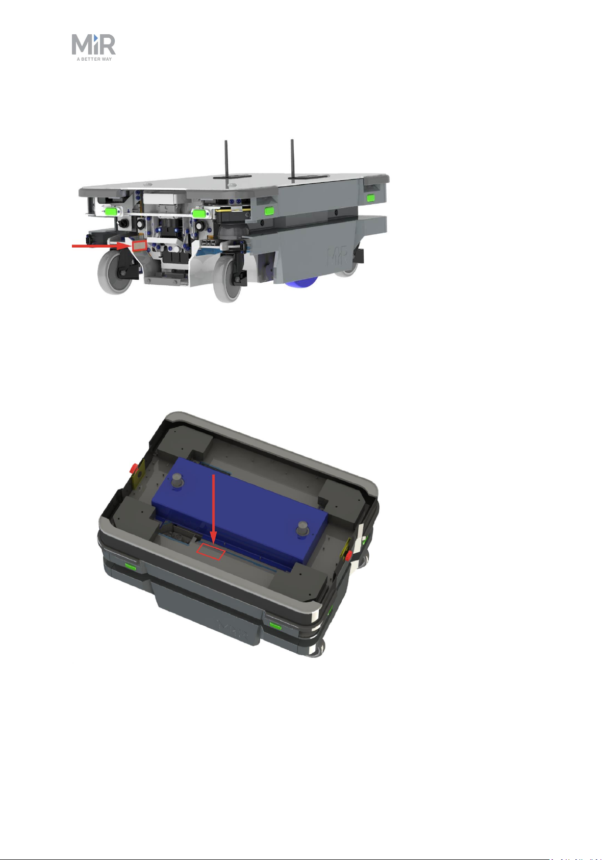
2. Product presentation
The identification label of MiR250 is located on the rear cover next to the battery.
Figure 2.2. Placement of the MiR250 identification label.
The identification label of MiR Shelf Carrier 250 is located on the left side of the shelf
carrier beneath its cover.
Figure 2.3. Placement of the MiR Shelf Carrier 250 identification label.
MiR250 Shelf Carrier User Guide (en) 03/2021 - v.1.4 ©Copyright 2021: Mobile IndustrialRobots A/S. 15
Page 16
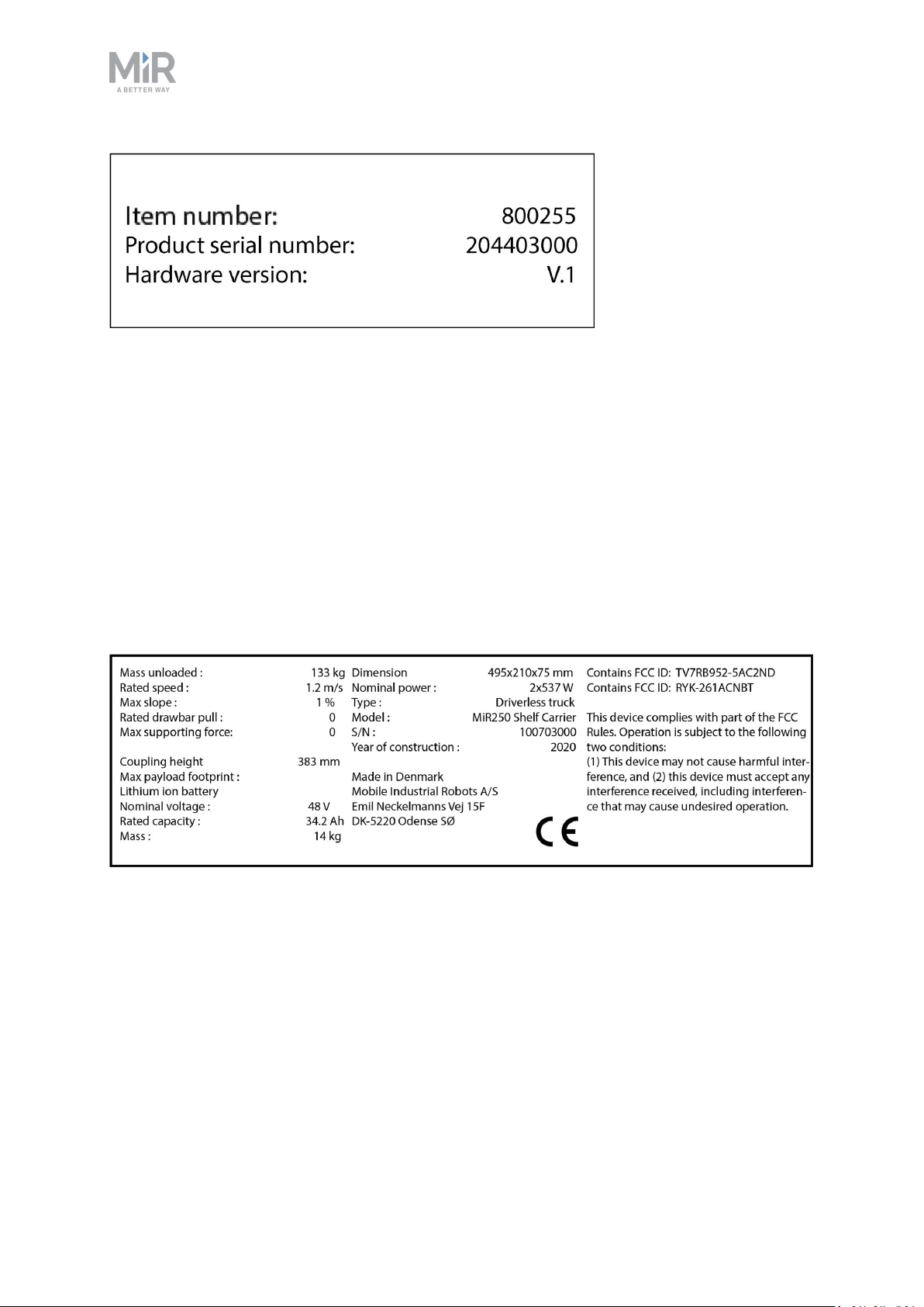
2. Product presentation
Figure 2.4. Example of a MiR Shelf Carrier 250 identification label.
Nameplate
Every MiR application is delivered with a nameplate that must be mounted to the robot. The
nameplate of MiR250 Shelf Carrier identifies the application model and serial number and
includes the CE mark, the technical specifications, and the address of Mobile Industrial
Robots. The nameplate identifies the complete MiR application, for example, a robot with a
top module.
It is the responsibility of the commissioner to mount the nameplate on the application—see
Mounting the nameplate on page65.
Figure 2.5. Example of a MiR250 Shelf Carrier nameplate.
Control panel
MiR250 Shelf Carrier has a control panel in the rear-left corner of the robot.
MiR250 Shelf Carrier User Guide (en) 03/2021 - v.1.4 ©Copyright 2021: Mobile IndustrialRobots A/S. 16
Page 17
The control panel buttons
2. Product presentation
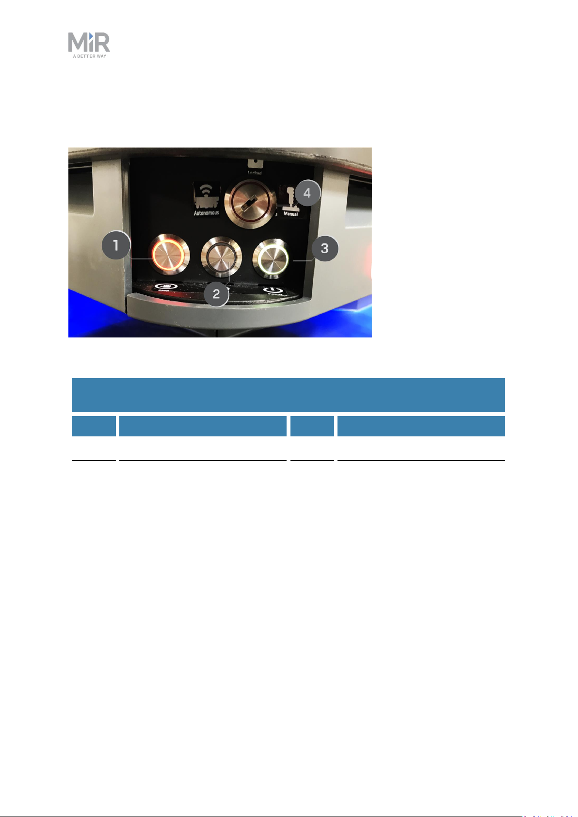
Figure 2.6. The MiR250 Shelf Carrier control panel.
Table 2.2.
Identification of items on the control panel in Figure 2.6
Pos. Description Pos. Description
1 Manual stop button 2 Resume button
3 Power button 4 Operating mode key
Manual stop
Pressing this button stops the robot. After pressing this button, you must press the Resume
button to let the robot continue operating.
Color indication:
• Red: It is possible to engage the Manual stop.
MiR250 Shelf Carrier User Guide (en) 03/2021 - v.1.4 ©Copyright 2021: Mobile IndustrialRobots A/S. 17
Page 18
2. Product presentation
Resume
Pressing this button:
• Clears the Emergency stop state.
• Lets the robot continue operating after the Manual stop button was pressed or after the
operating mode changes.
• Lets the robot start operating after powering up.
Color indication:
• Blinking blue: The robot is waiting for a user action (clear the Emergency stop state,
acknowledge the change of operating mode).
Power
Pressing this button for three seconds turns the robot on or shuts it off.
Color indication:
• Blue: The robot is off.
• Blinking green: The robot is starting up.
• Green: Normal operation.
• Blinking red: The battery level is too low to start without additional charging, or the robot
is shutting down.
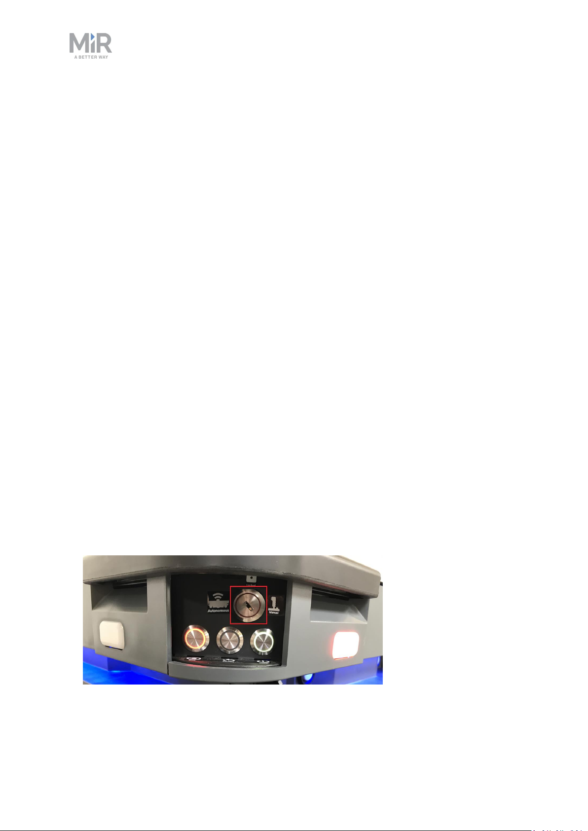
The Operating mode key
The Operating mode key lets you switch between operating modes.
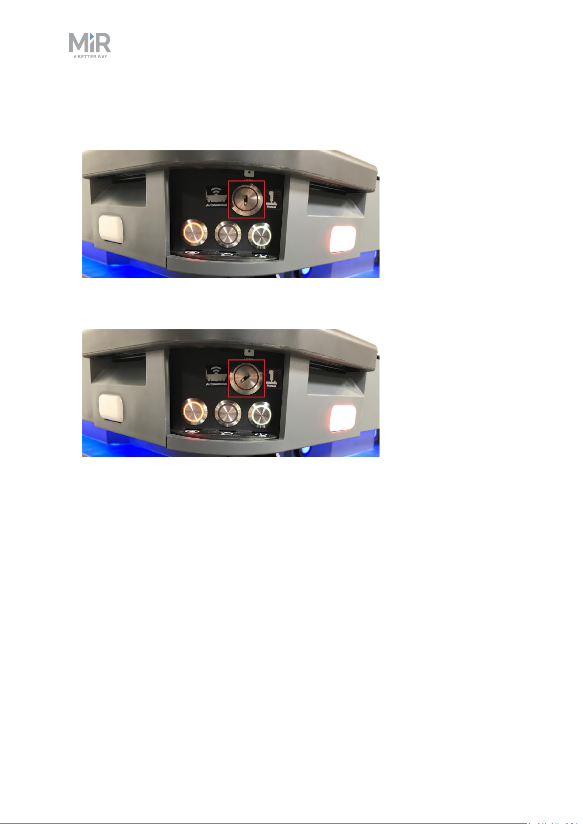
• Left position: Autonomous mode
Puts the robot in Autonomous mode.
MiR250 Shelf Carrier User Guide (en) 03/2021 - v.1.4 ©Copyright 2021: Mobile IndustrialRobots A/S. 18
Page 19
2. Product presentation
• Middle position: Locked
Locks the robot. The robot blocks the wheels; you cannot start a mission or drive the robot
manually.
• Right position: Manual mode
Puts the robot in Manual mode.
For more information on operating modes, see Operating modes on the next page.
Manual brake release switch
The Manual brake release switch is located below the control panel and releases the
mechanical brakes on MiR250 Shelf Carrier. You release the robot's mechanical brakes by
turning the Manual brake release switch clockwise.
MiR250 Shelf Carrier User Guide (en) 03/2021 - v.1.4 ©Copyright 2021: Mobile IndustrialRobots A/S. 19
Page 20
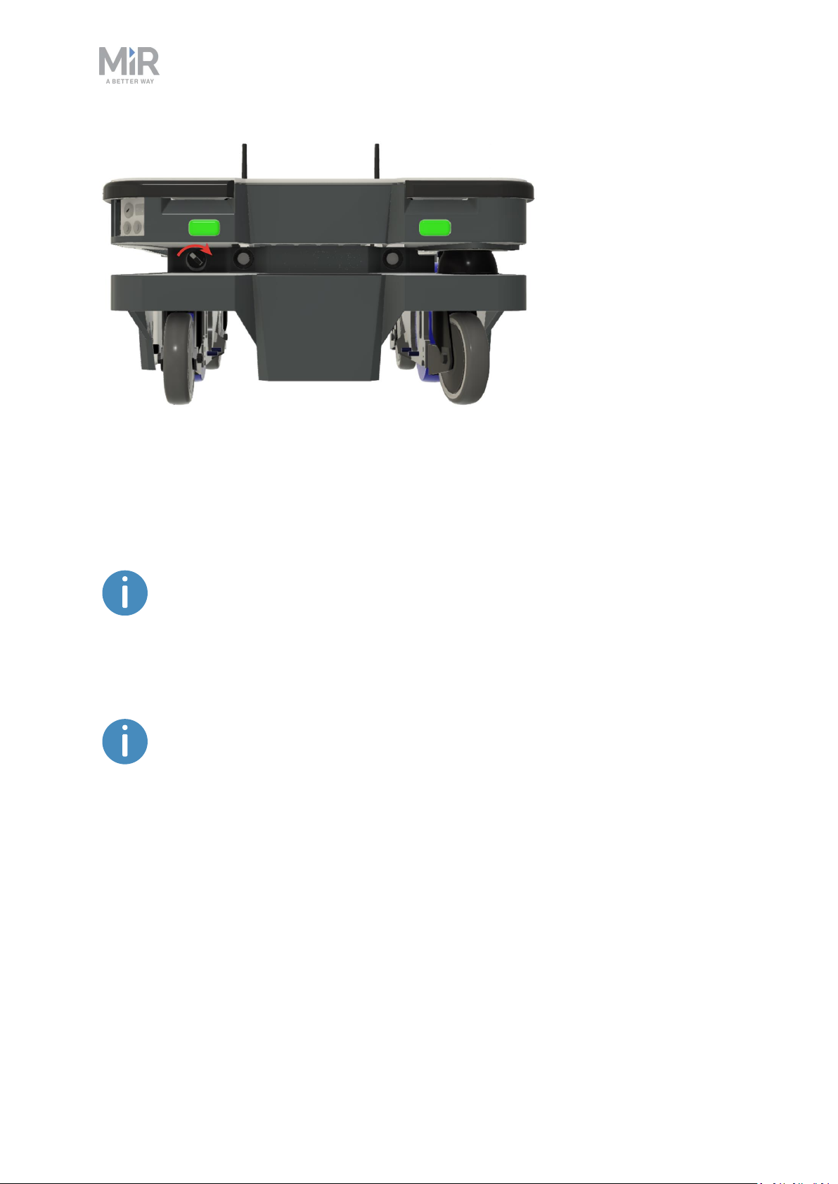
Figure 2.7. The manual brake release switch is located below the control panel.
2. Product presentation
The mechanical brakes require electrical power to be released, so if the robot is without
power, the mechanical brakes cannot be released. You can see if the robot is powered, by
checking if the Power button on the control panel lights up.
If MiR250 Shelf Carrier shuts down due to low battery percentage, there is still
enough power to release the brakes for approximately a week after.
When driving in Autonomous mode, the robot engages and releases the mechanical brakes
automatically.
The robot cannot operate while the mechanical brakes are released manually.
Operating modes
MiR250 Shelf Carrier has two operating modes: Manual mode and Autonomous mode.
Manual mode
In this mode, you can drive the robot manually using the joystick in the robot interface. Only
one person can control the robot manually at a time. To ensure that nobody else takes
control of the robot, the robot issues a token to the device on which you activate the Manual
MiR250 Shelf Carrier User Guide (en) 03/2021 - v.1.4 ©Copyright 2021: Mobile IndustrialRobots A/S. 20
Page 21
2. Product presentation
mode.
For information about activating this mode, see Driving the robot in Manual mode on
page59.
Autonomous mode
In this mode, the robot executes the programmed missions. After switching the key to this
mode, you can remove the key, and the robot will continue driving autonomously. In
Autonomous mode, the joystick is disabled in the robot interface.
2.3 Internal parts
Most internal parts of MiR250 Shelf Carrier are accessed through covers that open to
different compartments:
• Front compartment
• Rear compartment
• Side compartments
• Top compartments
To access the compartments correctly, see Accessing the internal parts on page43.
WARNING
Removing covers from the robot exposes parts connected to the power supply,
risking damage to the robot from a short circuit and electrical shock to
personnel.
• Before removing any covers, turn off the robot, and disconnect the
battery—see Disconnecting the battery on page74.
Front compartment
The front compartment holds several electronic components, such as the robot computer
and the motor controller carrier board.
MiR250 Shelf Carrier User Guide (en) 03/2021 - v.1.4 ©Copyright 2021: Mobile IndustrialRobots A/S. 21
Page 22
2. Product presentation
To open the front compartment, see Accessing the internal parts on page43.
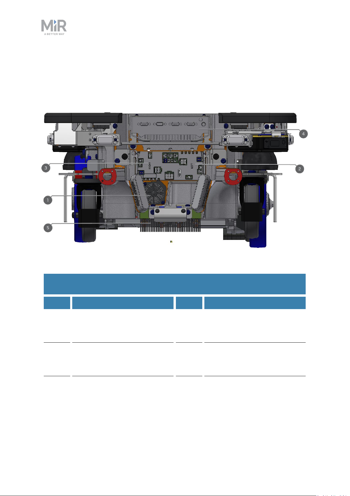
Front compartment components
The front compartment components are listed in Table 2.3.
Figure 2.8. Internal parts of the front compartment.
Table 2.3.
Identification of internal parts in Figure 2.8
Pos. Description Pos. Description
1 Loudspeaker 2 Carrier board with motor
controller controlling the leftside drivetrain
3 Carrier board with motor
4 Robot computer
controller controlling the rightside drivetrain
5 Charging pads under robot and
broom for keeping dirt away
from the charging pads
MiR250 Shelf Carrier User Guide (en) 03/2021 - v.1.4 ©Copyright 2021: Mobile IndustrialRobots A/S. 22
Page 23

2. Product presentation
Rear compartment
The rear compartment holds the robot’s battery, Battery disconnect lever, power board, and
safety PLC. The battery and Battery disconnect lever can be accessed without the use of
tools. The other components in the rear compartment are only accessible via use of tools.
To open the rear compartment, see Accessing the internal parts on page43.
NOTICE
The unique nameplate of your robot is to be mounted on the rear
compartment cover—see Mounting the nameplate on page65. Make sure you
do not swap the cover with covers from other robots.
MiR250 Shelf Carrier User Guide (en) 03/2021 - v.1.4 ©Copyright 2021: Mobile IndustrialRobots A/S. 23
Page 24
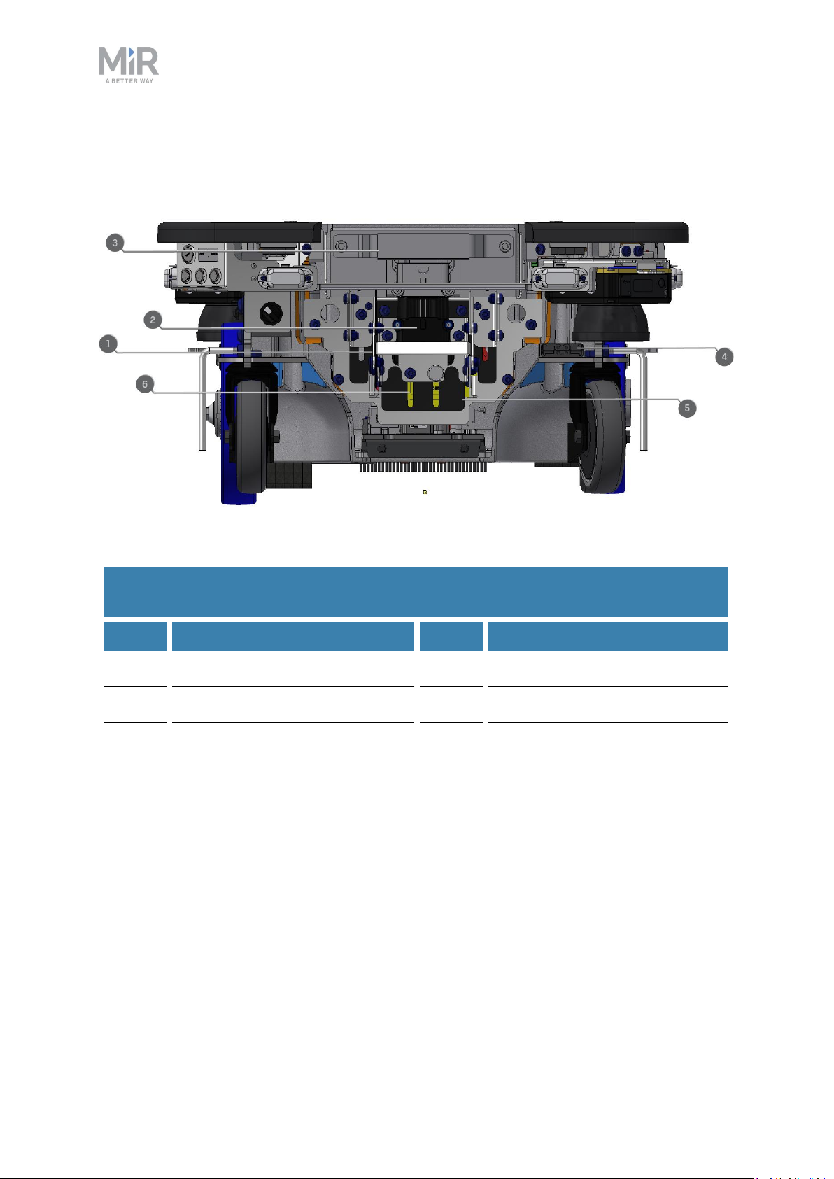
Rear compartment components
The rear compartment components are listed in Table 2.4.
2. Product presentation
Figure 2.9. Internal parts of the rear compartment.
Table 2.4.
Identification of internal parts in Figure 2.9
Pos. Description Pos. Description
1 Battery disconnect lever 2 Battery connector
3 Battery 4 Cable charging interface
5 Power board for motor
controller, robot computer, and
safety PLC
6 Safety PLC
Side compartments
The side compartments contain the bogies and drive wheels.
To access a side compartment, see Accessing the internal parts on page43.
Side compartment components
The left side compartment components are listed in Table 2.5
MiR250 Shelf Carrier User Guide (en) 03/2021 - v.1.4 ©Copyright 2021: Mobile IndustrialRobots A/S. 24
Page 25
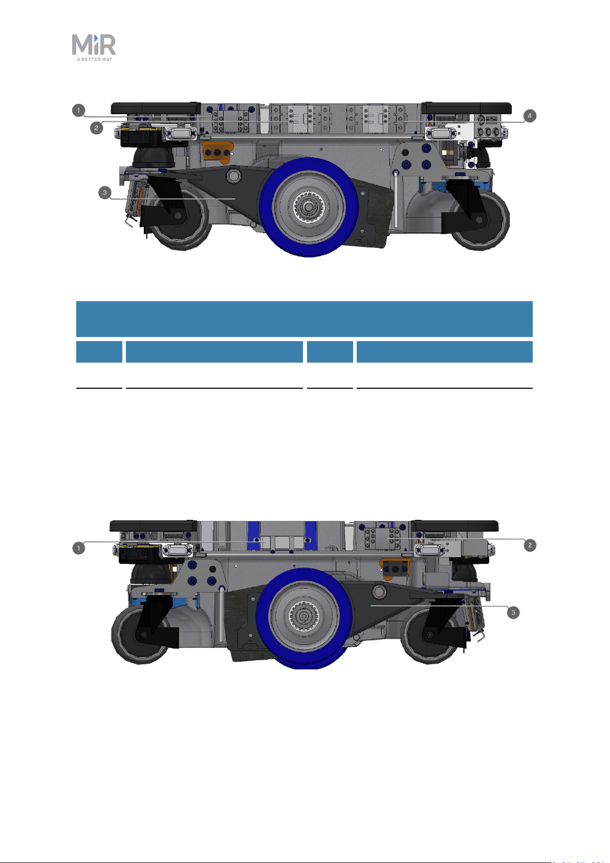
Figure 2.10. Internal parts of the left side compartment.
Table 2.5.
Identification of internal parts in Figure 2.10
2. Product presentation
Pos. Description Pos. Description
1 Safe Stop 1 (SS1) contactor 2 Safe Torque Off (STO) contactor
3 Bogie and drivetrain consisting
4 Safe Torque Off (STO) contactor
of motor, gearbox, encoder,
brake, drive wheel, and
assembly parts
The right side compartment components are listed in Table 2.6
Figure 2.11. Internal parts of the right side compartment.
MiR250 Shelf Carrier User Guide (en) 03/2021 - v.1.4 ©Copyright 2021: Mobile IndustrialRobots A/S. 25
Page 26

2. Product presentation
Table 2.6.
Identification of internal parts in Figure 2.11
Pos. Description Pos. Description
1 Router 2 Safe Stop 1 (SS1) contactor
3 Bogie and drivetrain consisting
of motor, gearbox, encoder,
brake, drive wheel, and
assembly parts
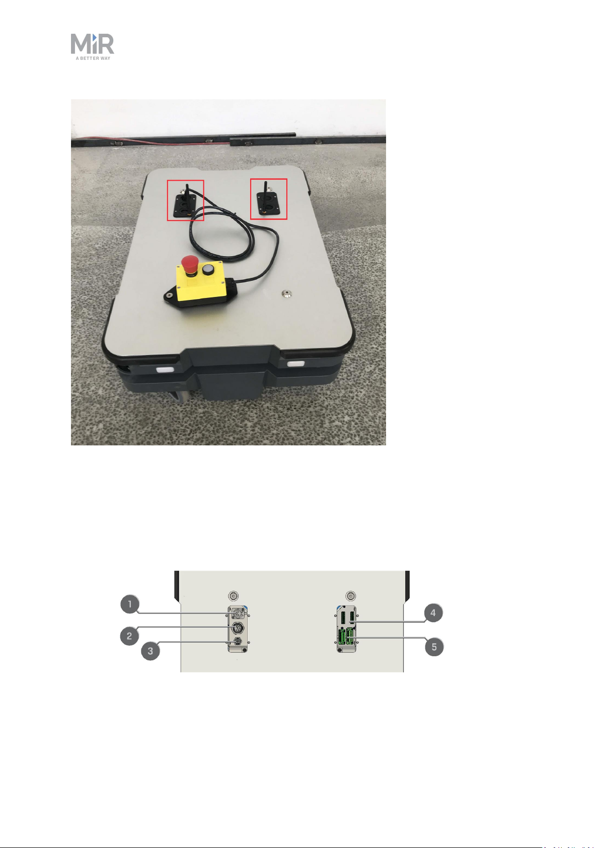
Top compartments
The two top compartments contain electrical interfaces that can be connected to top
modules.
The top compartments are only accessible after the top module has been
removed—see Unmounting the top module on page215.
MiR250 Shelf Carrier User Guide (en) 03/2021 - v.1.4 ©Copyright 2021: Mobile IndustrialRobots A/S. 26
Page 27
2. Product presentation
Figure 2.12. The top compartments on the robot.
Top compartment components
The top compartments interfaces are listed in Table 2.7. For detailed information on
electrical interfaces, see Interface specifications on page236.
Figure 2.13. Interfaces in the top compartments.
MiR250 Shelf Carrier User Guide (en) 03/2021 - v.1.4 ©Copyright 2021: Mobile IndustrialRobots A/S. 27
Page 28

2. Product presentation
Table 2.7.
Identification of interfaces in Figure 2.13
Pos. Description Pos. Description
1 Emergency stop 2 Auxiliary power connector
3 Ethernet 4 General purpose I/Os
5 Auxiliary safety functions I/Os
MiR Shelf Carrier 250
Within the shelf carrier top module there is an actuator and a lifting device to raise and
lower the pins, sensor switches, and safety contactors.
To access the internal parts of MiR Shelf Carrier 250, see Accessing the internal parts on
page43.
MiR Shelf Carrier 250 components
The components of MiR Shelf Carrier 250 are listed in Table 2.8.
MiR250 Shelf Carrier User Guide (en) 03/2021 - v.1.4 ©Copyright 2021: Mobile IndustrialRobots A/S. 28
Page 29

2. Product presentation
Figure 2.14. Internal parts in MiR Shelf Carrier 250.
Table 2.8.
Identification of internal parts in Figure 2.14
Pos. Description Pos. Description
1 Front Emergency stop button 2 Carrier pins
3 Position switches 4 GPIOconnectors
5 Auxiliary safety IO connectors 6 Safety contactors K1 and K2
7 Rear Emergency stop button 8 Lifting mechanism and actuator
9 Emergency stop connector
MiR250 Shelf Carrier User Guide (en) 03/2021 - v.1.4 ©Copyright 2021: Mobile IndustrialRobots A/S. 29
Page 30

2. Product presentation
2.4 How MiR Shelf Carrier 250 works
When MiR250 Shelf Carrier docks to a shelf, the carrier pins can be raised to pick up a shelf
and lowered to place a shelf at a shelf position.
MiR250 Shelf Carrier uses I/O modules in the safety PLC to control the carrier pins.The
robot uses two inputs and two outputs to communicate with MiR Shelf Carrier 250.
The outputs are used to control the position of MiR Shelf Carrier 250, and the inputs are
used to signal the current position of the MiR Shelf Carrier 250—see Testing the top module
on page69.
To see the menu options for the I/O modules under Setup >IO modules, you must enable
them first—see Enable the MiR250 Shelf Carrier feature on page67.
Table 2.9.
Descriptions of how the robot's internal outputs control the shelf carrier
Output Function
2 Lowers the carrier pins when active.
3 Raises the carrier pins when active.
Table 2.10.
Descriptions of what the robot's internal inputs signal regarding the status of the shelf
carrier
Input Function
2 Is active when the carrier pins are down.
3 Is active when the carrier pins are up.
MiR250 Shelf Carrier User Guide (en) 03/2021 - v.1.4 ©Copyright 2021: Mobile IndustrialRobots A/S. 30
Page 31

3. Warranty
Mobile Industrial Robots offers a standard warranty on all products.
Contact your distributor to see the terms and extend of product coverage.
NOTICE
Mobile Industrial Robots disclaims any and all liability if MiR250 Shelf Carrier
or its accessories are damaged, changed, or modified in any way. Mobile
Industrial Robots cannot be held responsible for any damages caused to
MiR250 Shelf Carrier, accessories, or any other equipment due to
programming errors or malfunctioning of MiR250 Shelf Carrier.
3. Warranty
MiR250 Shelf Carrier User Guide (en) 03/2021 - v.1.4 ©Copyright 2021: Mobile IndustrialRobots A/S. 31
Page 32

4. Safety
4. Safety
Read the information in this section before powering up and operating MiR250 Shelf Carrier.
Pay particular attention to the safety instructions and warnings.
NOTICE
Mobile Industrial Robots disclaims any and all liability if MiR250 Shelf Carrier
or its accessories are damaged, changed, or modified in any way. Mobile
Industrial Robots cannot be held responsible for any damages caused to
MiR250 Shelf Carrier, accessories, or any other equipment due to
programming errors or malfunctioning of MiR250 Shelf Carrier.
4.1 Safety message types
This document uses the following safety message types.
WARNING
Indicates a potentially hazardous situation that could result in death or serious
injury. Carefully read the message that follows to prevent death or serious
injury.
CAUTION
Indicates a potentially hazardous situation that could result in minor or
moderate injury. Alerts against unsafe practices. Carefully read the message
that follows to prevent minor or moderate injury.
NOTICE
Indicates important information, including situations that can result in damage
to equipment or property.
MiR250 Shelf Carrier User Guide (en) 03/2021 - v.1.4 ©Copyright 2021: Mobile IndustrialRobots A/S. 32
Page 33

4.2 General safety precautions
This section contains general safety precautions.
WARNING
If the robot is not running the correct software and is therefore not functioning
properly, the robot may collide with personnel or equipment causing injury or
damage.
• Ensure that the robot is always running the correct software.
WARNING
4. Safety
When the robot is in an operating hazard zone, there is a risk of injury to any
personnel within the zone.
• Ensure that all personnel are instructed to stay clear of operating hazard
zones when the robot is in or approaching the zone.
WARNING
The robot may drive over the feet of personnel, causing injury.
• All personnel must be informed of the side Protective fields of the robot and
be instructed to wear safety shoes near an operating robot—see Personnel
detection on page104.
WARNING
The robot may drive into a ladder, scaffold, or similar equipment that has a
person standing on it. Personnel risk fall injuries and equipment may be
damaged.
• Don't place ladders, scaffolds, or similar equipment in the robot's work
environment.
MiR250 Shelf Carrier User Guide (en) 03/2021 - v.1.4 ©Copyright 2021: Mobile IndustrialRobots A/S. 33
Page 34

WARNING
The robot may drive down staircases or holes in the floor and cause serious
injury to personnel and damage to the robot and to equipment.
• Mark descending staircases and holes as Forbidden zones on maps.
• Keep the maps up to date.
• Inform personnel that the robot cannot detect descending staircases and
holes in the floor in time to stop.
WARNING
Contact with live electrical parts can cause electric shock.
4. Safety
• Do not touch any internal components of the robot while it is powered.
WARNING
Using a charging device different from the one supplied by the manufacturer
can cause a fire and thereby burn injuries to nearby personnel and damage to
the robot and equipment.
• Only use an original MiR charger.
WARNING
Attempting to charge batteries outside the robot can lead to electrical shock
or burns.
• Never charge the batteries outside the robot.
MiR250 Shelf Carrier User Guide (en) 03/2021 - v.1.4 ©Copyright 2021: Mobile IndustrialRobots A/S. 34
Page 35
4. Safety
WARNING
Lithium battery packs may get hot, explode, or ignite and cause serious injury
if they are misused electrically or mechanically.
Observe the following precautions when handling and using lithium-ion
batteries:
• Do not short-circuit, recharge, or connect with false polarity.
• Do not expose to temperatures beyond the specified temperature range or
incinerate the battery.
• Do not crush, puncture, or disassemble the battery. The battery contains
safety and protection devices, which, if damaged, may cause the battery to
generate heat, explode, or ignite.
• Do not allow the battery to get wet.
• In the event the battery leaks and the fluid gets into one’s eye, do not rub
the eye. Rinse well with water, and immediately seek medical care. If left
untreated, the battery fluid could cause damage to the eye.
• Use only an original MiR charger (cable charger or charging station) and
always follow the instructions from the battery manufacturer.
• Do not touch damaged batteries with bare hands. Only personnel using
suitable Personal Protection Equipment (PPE) and tools should handle
damaged batteries.
• Isolate the battery and keep clear if the following conditions are observed:
• The battery exhibits abnormally high temperatures.
• The battery emits abnormal odors.
• The battery changes colors.
• The battery case is deformed or otherwise differs from the normal
electrical or mechanical condition.
• Modifications or manipulations of the battery may lead to considerable
safety risks and are therefore prohibited.
• Do not use the battery for anything other than MiR250 Shelf Carrier.
MiR250 Shelf Carrier User Guide (en) 03/2021 - v.1.4 ©Copyright 2021: Mobile IndustrialRobots A/S. 35
Page 36

4. Safety
WARNING
Load falling or robot overturning if the load on the robot is not positioned or
fastened correctly can cause fall injuries to nearby personnel or damage to
equipment.
• Ensure that the load is positioned according to the specifications and is
fastened correctly—see Payload distribution on page229.
WARNING
Personnel standing next to the robot when it is docking to a shelf risk being
injured by an impact.
• Ensure that docking positions are clearly marked as operating hazard zones
with visible tape or similar marking and that all personnel are instructed
not to stand in the hazard zone when the robot is docking.
WARNING
The robot risks damage and mechanical failure if it is used to transport pallets
or anything other than safely commissioned shelves. Nearby equipment and
personnel risk damage or injury if payloads fall from the robot.
• Only use the robot to transport safely commissioned shelves—see Shelf
specifications on page120.
WARNING
Personnel standing in the blind spot of the robot when it is pivoting with a shelf
risk being struck and injured.
• Ensure that all nearby personnel are instructed not to stand close to the
robot when it is pivoting.
• Inform personnel that the signal lights indicate when the robot is intending
to turn or pivot—see Light indicators and speakers on page113.
MiR250 Shelf Carrier User Guide (en) 03/2021 - v.1.4 ©Copyright 2021: Mobile IndustrialRobots A/S. 36
Page 37

WARNING
Ifa load is positioned incorrectly on a shelf, the load may fall off. Nearby
personnel or equipment risk injury or damage.
• Ensure that each load is positioned correctly on the shelf.It is the
responsibility of the commissioner to determine correct and safe methods
of loading shelves.
• Conduct a brake test while the robot is transporting a fully loaded shelf—
see Making a brake test on page150.
WARNING
If the robot attempts to dock to a shelf and the carrier pins are raised or the
robot is misplaced, the robot may push the shelf. The shelf may collide with
personnel or equipment, resulting in injury or damage.
4. Safety
• Ensure that docking positions are clearly marked as operating hazard zones
with visible tape or similar marking, and that all personnel are instructed
not to stand close to the robot when it is docking.
WARNING
If the robot does not attach to the shelf correctly due to pins being offset from
their correct positions, the shelf can detach at any time. Uncertain control of
the shelf may result in the shelf or its load colliding with personnel or
equipment resulting in injury or damage.
• Ensure the shelf is designed according to specifications—see Shelf
specifications on page120.The laser scanners will then be able to detect if
the shelf is incorrectly positioned and will enter Protective stop before
operating with the shelf.
MiR250 Shelf Carrier User Guide (en) 03/2021 - v.1.4 ©Copyright 2021: Mobile IndustrialRobots A/S. 37
Page 38
4. Safety
WARNING
If the robot drives on a slope and looses grip of the attached shelf, the shelf or
its load may collide with personnel or equipment causing injury or damage.
• Do not operate MiR250 Shelf Carrier on slopes.
WARNING
If the robot transports a shelf with a load that extends the footprint of the
robot, the load may collide with personnel or equipment causing injury or
damage.
• Do not load the shelves with loads that exceed the robot's footprint.
CAUTION
Robot malfunctions can cause an electrical fire, causing damage and injury to
equipment and personnel.
• Personnel operating near the robot must be informed on how to use an ABC
fire extinguisher to put out an electrical fire should the robot malfunction
and catch on fire.
CAUTION
Risk of trapping or injury to personnel if robots malfunction or if personnel
enter operating hazard zones.
• Personnel operating near the robot must be informed on how to engage the
robot's Emergency stop function in emergency situations.
4.3 Intended use
MiR250 Shelf Carrier is intended to be commissioned and used in indoor industrial
environments where access for the public is restricted. For details about the environmental
conditions in which MiR250 Shelf Carrier should operate, see specifications for MiR250 Shelf
MiR250 Shelf Carrier User Guide (en) 03/2021 - v.1.4 ©Copyright 2021: Mobile IndustrialRobots A/S. 38
Page 39

4. Safety
Carrier on the MiR website.
MiR250 Shelf Carrier is intended to be commissioned according to the guidelines in
Commissioning on page117. This is a prerequisite for safe usage of MiR250 Shelf Carrier.
MiR250 Shelf Carrier is equipped with safety-related features that are purposely designed
for collaborative operation where the robot operates without a safety enclosure or together
with people.
MiR250 Shelf Carrier is designed for and all risks are considered when it is used to transport
shelves that fulfill the specification and design requirement described in Shelf specifications
on page120.
MiR250 Shelf Carrier is a completed MiR application that consists of a MiR250 with a
mounted MiR Shelf Carrier 250. The application is CE marked as long as it is not modified or
altered. However, a CE marked application does not guarantee a CE marked setup. It is the
responsibility of the commissioner to commission MiR250 Shelf Carrier safely.
NOTICE
A safe machine does not guarantee a safe system. Follow the guidelines in
Commissioning on page117 to ensure a safe system.
4.4 Users
MiR250 Shelf Carrier is only intended to be used by personnel that have received training in
their required tasks.
There are three types of intended users for MiR250 Shelf Carrier: commissioners, operators,
and direct users.
Commissioners
Commissioners have thorough knowledge of all aspects of commissioning, safety, use, and
maintenance of MiR250 Shelf Carrier and have the following main tasks:
• Commissioning of the product. This includes creating maps and restricting the user
interface for other users and making brake tests with a full payload.
• Conducting the risk assessment.
MiR250 Shelf Carrier User Guide (en) 03/2021 - v.1.4 ©Copyright 2021: Mobile IndustrialRobots A/S. 39
Page 40

4. Safety
• Determining the payload limit, weight distribution, safe fastening methods, safe loading
and unloading of loads on MiR250 Shelf Carrier, and ergonomic loading and unloading
methods if relevant.
• Ensuring the safety of nearby personnel when the robot is accelerating, braking, and
maneuvering.
• Marking operating hazard zones.
Operators
Operators have thorough knowledge of MiR250 Shelf Carrier and of the safety precautions
presented in this user guide. Operators have the following main tasks:
• Servicing and maintaining MiR250 Shelf Carrier.
• Creating and changing missions and map features in the robot interface.
Direct users
Direct users are familiar with the safety precautions in this user guide and have the
following main tasks:
• Assigning missions to MiR250 Shelf Carrier.
• Fastening loads to MiR250 Shelf Carrier securely.
• Loading and unloading from a paused robot.
All other persons in the vicinity of MiR250 Shelf Carrier are considered indirect users and
must know how to act when they are close to the robot. For example, they must be aware
that visibly marked operating hazard zones must be respected.
4.5 Foreseeable misuse
Any use of MiR250 Shelf Carrier deviating from the intended use is deemed as misuse. This
includes, but is not limited to:
• Using the robot to transport people
• Using the robot on steep surface grades, such as ramps
• Making changes to the SICK configuration
• Driving the robot on cross slopes
• Exceeding the total payload
• Positioning or fastening loads incorrectly according to the specifications—see Payload
distribution on page229
MiR250 Shelf Carrier User Guide (en) 03/2021 - v.1.4 ©Copyright 2021: Mobile IndustrialRobots A/S. 40
Page 41

4. Safety
• Using Emergency stop buttons for anything other than emergency stops
• Driving the robot with anything other than safely commissioned shelves
• Using the robot in medical and life critical applications
• Operating the robot outside the permissible operating parameters and environmental
specifications
• Using the robot in potentially explosive environments
• Using the robot outdoors
• Using the robot in hygiene zones
4.6 Warning label
MiR250 Shelf Carrier is supplied with a warning label that specifies that it is strictly
prohibited to ride on the robot.
The label must be placed on the robot or top module so that it is clearly visible.
Figure 4.1. The warning label must be placed on the robot or top module.
4.7 Residual risks
Mobile Industrial Robots has identified the following potential hazards that commissioners
must inform personnel about and take all precautions to avoid when working with MiR250
Shelf Carrier:
• You risk being run over, drawn in, trapped, or struck if you stand in the path of the robot
or walk towards the robot or its intended path while it is in motion.
• You risk being run over, drawn in, trapped, or struck if you stand in the path of the robot
or walk towards it while it is driving in reverse. The robot only drives in reverse when
undocking from a marker, such as a charging station or load transfer station.
• You risk being crushed or trapped if you touch the robot while it is in motion.
MiR250 Shelf Carrier User Guide (en) 03/2021 - v.1.4 ©Copyright 2021: Mobile IndustrialRobots A/S. 41
Page 42

4. Safety
• You risk being run over, drawn in, trapped, or struck if you stand in the path of the robot
or walk towards it while it is docking to a shelf.
• You risk being crushed or trapped between the robot and a shelf while the carrier is
picking up a shelf.
• You risk being crushed or trapped if the robot places a load outside a designated drop-off
area due to faulty localization.
• You risk losing control of the robot if it is accessed by unauthorized users. Consider
increasing the IT security of your product—see IT security on page82.
NOTICE
Other significant hazards may be present in a specific robot installation and
must be identified during commissioning.
MiR250 Shelf Carrier User Guide (en) 03/2021 - v.1.4 ©Copyright 2021: Mobile IndustrialRobots A/S. 42
Page 43

5. Accessing the internal parts
5. Accessing the internal parts
Most internal parts of MiR250 Shelf Carrier are accessed through covers that open to
different compartments:
• Front compartment
• Rear compartment
• Side compartments
• Top compartments
For more information on how to remove the covers on MiR250, see the video
How to remove and attach the covers on MiR250 on MiR Academy at the MiR
website. Contact your distributor for access to MiR Academy.
WARNING
Removing covers from the robot exposes parts connected to the power supply,
risking damage to the robot from a short circuit and electrical shock to
personnel.
• Before removing any covers, turn off the robot, and disconnect the
battery—see Disconnecting the battery on page74.
MiR250 Shelf Carrier User Guide (en) 03/2021 - v.1.4 ©Copyright 2021: Mobile IndustrialRobots A/S. 43
Page 44
5. Accessing the internal parts
5.1 Front compartment
To open the front compartment, follow these steps:
1. Unscrew the two screws holding the front cover with a T30 Torx screwdriver.
2. Pull the front cover off of the robot.
MiR250 Shelf Carrier User Guide (en) 03/2021 - v.1.4 ©Copyright 2021: Mobile IndustrialRobots A/S. 44
Page 45

5. Accessing the internal parts
5.2 Rear compartment
To open the rear compartment, follow these steps:
1. Push the two white buttons at the same time.
2. Loosen the cover by first loosening the bottom corners one at the time, then the two top
corners. Pull down and then out on each top corner.
MiR250 Shelf Carrier User Guide (en) 03/2021 - v.1.4 ©Copyright 2021: Mobile IndustrialRobots A/S. 45
Page 46

3. Pull off the cover.
5. Accessing the internal parts
5.3 Side compartments
The front and rear covers have to be removed before you can remove the side
covers.
To open a side compartment, follow these steps:
1. Turn the two screws counterclockwise with a T30 Torx screwdriver.
MiR250 Shelf Carrier User Guide (en) 03/2021 - v.1.4 ©Copyright 2021: Mobile IndustrialRobots A/S. 46
Page 47

2. Pull the cover off.
5.4 MiR Shelf Carrier 250
5. Accessing the internal parts
To access the internal parts of MiR Shelf Carrier 250, remove the top plate of the shelf
carrier by unscrewing all 14 screws from the top plate and lifting off the plate.
MiR250 Shelf Carrier User Guide (en) 03/2021 - v.1.4 ©Copyright 2021: Mobile IndustrialRobots A/S. 47
Page 48

6. Getting started
This section describes how to get started with MiR250 Shelf Carrier.
NOTICE
To be able to use MiR250 Shelf Carrier, your robot must be running software
version 2.9.0 or higher.
NOTICE
Read Safety on page32 before powering up MiR250 Shelf Carrier.
6. Getting started
In some images in this section, the robot is shown without a MiR Shelf Carrier
250 top module.
6.1 In the box
This section describes the contents of the MiR250 Shelf Carrier box.
MiR250 Shelf Carrier User Guide (en) 03/2021 - v.1.4 ©Copyright 2021: Mobile IndustrialRobots A/S. 48
Page 49

6. Getting started
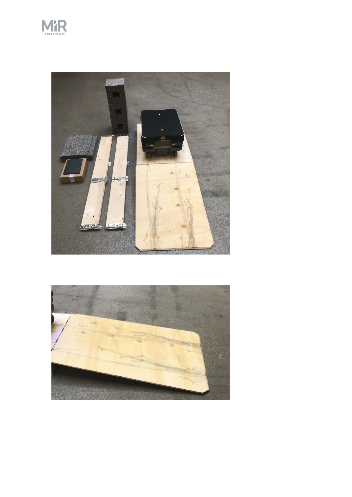
Figure 6.1. The box containing the robot and accessories.
The box contains:
• The MiR250 Shelf Carrier robot
• A MiR250 Shelf Carrier document folder containing a USB flash drive and the following
printed documents:
• MiR250 Shelf Carrier Quick Start
• The CE Declaration of Conformity for your robot
• The CE Declaration of Conformity for your application
• Getting the robot online
• Passwords
• The unique nameplate for your application
• The USB flash drive in the document folder has the following content:
• MiR250 Shelf Carrier User Guide
• MiR250 Shelf Carrier Quick Start
• MiR Network and WiFi Guide
• MiR Robot Reference Guide
• MiR Robot REST API Reference
• Getting the robot online
MiR250 Shelf Carrier User Guide (en) 03/2021 - v.1.4 ©Copyright 2021: Mobile IndustrialRobots A/S. 49
Page 50

6. Getting started
6.2 Unpacking MiR250 Shelf Carrier
This section describes how to unpack the robot.
Keep the original packaging for future transportation of MiR250 Shelf Carrier.
To unpack the robot, follow these steps:
1. Place the box with the robot so that there is at least three meters of free space at the
front or the back of the box. This is necessary as the robot drives out of the box on a
ramp.
2. Cut the protective straps surrounding the box.
MiR250 Shelf Carrier User Guide (en) 03/2021 - v.1.4 ©Copyright 2021: Mobile IndustrialRobots A/S. 50
Page 51

3. Remove the lid from the box.
6. Getting started
4. Take the folder with the printed documents and the USB flash drive out of the box.
MiR250 Shelf Carrier User Guide (en) 03/2021 - v.1.4 ©Copyright 2021: Mobile IndustrialRobots A/S. 51
Page 52
5. Remove the walls of the box and the protective foam blocks.
6. Getting started
6. Place the lid of the box so that you can use it as a ramp. Align the lid so that it is flush
with the base of the box.
MiR250 Shelf Carrier User Guide (en) 03/2021 - v.1.4 ©Copyright 2021: Mobile IndustrialRobots A/S. 52
Page 53

6. Getting started
6.3 Connecting the battery
To connect the battery to the robot, you need to open the rear compartment—see Accessing
the internal parts on page43.
To connect the battery to the robot, follow these steps:
1. Turn the battery lever lock clockwise to unlock the battery lever.
2. Pull up the lever to connect the battery connector to the battery. Then turn the battery
lever lock counterclockwise to secure the battery lever.
MiR250 Shelf Carrier User Guide (en) 03/2021 - v.1.4 ©Copyright 2021: Mobile IndustrialRobots A/S. 53
Page 54

6. Getting started
3. Reattach the rear cover by tilting it slightly so that the bottom point forward and insert it
into the two attachment sockets. Press the two white buttons while attaching the cover to
the robot.
4. Click the cover in place one corner at the time.
MiR250 Shelf Carrier User Guide (en) 03/2021 - v.1.4 ©Copyright 2021: Mobile IndustrialRobots A/S. 54
Page 55

6.4 Powering up the robot
To power up the robot, follow these steps:
6. Getting started
MiR250 Shelf Carrier User Guide (en) 03/2021 - v.1.4 ©Copyright 2021: Mobile IndustrialRobots A/S. 55
Page 56

6. Getting started
1. Press the Power button for three seconds to turn on the robot.
The status lights waver yellow, and the robot starts the software initialization process.
MiR250 Shelf Carrier User Guide (en) 03/2021 - v.1.4 ©Copyright 2021: Mobile IndustrialRobots A/S. 56
Page 57

When the initialization process ends, the robot goes into Protective stop.
6. Getting started
2. Press the Resume button to clear the Protective stop. The robot is now ready for
operation.
MiR250 Shelf Carrier User Guide (en) 03/2021 - v.1.4 ©Copyright 2021: Mobile IndustrialRobots A/S. 57
Page 58

6. Getting started
6.5 Connecting to the robot interface
When the robot is turned on, it enables the connection to its WiFi access point. The name of
the access point appears in the list of available connections on your PC, tablet, or phone.
NOTICE
The original username and password for the robot’s web interface are in the
document Getting the robot online.
The unique password for the WiFi access point is in the Passwords document.
Both documents are in the box with the product.
To connect to the robot interface, follow these steps:
1. Using your PC, tablet, or phone, connect to the WiFi access point of the robot using the
unique password for the WiFi access point. The access point name has the following
format: MiR_20XXXXXXX.
The access point name is derived from the robot application's model serial
number.
MiR250 Shelf Carrier User Guide (en) 03/2021 - v.1.4 ©Copyright 2021: Mobile IndustrialRobots A/S. 58
Page 59

2. In a browser, go to the address mir.com and sign in.
6. Getting started
3. Switch to Manual mode, and drive the robot down the ramp—see Driving the robot in
Manual mode below.
6.6 Driving the robot in Manual mode
CAUTION
When driving the robot in Manual mode, it is possible to mute the Protective
fields and drive the robot into Forbidden zones and Unpreferred zones on the
map. This means that the robot will only stop when it is very close to an
obstacle and will not respond to zones on the map. This can result in injury to
personnel or damage to equipment if the robot is not driven carefully.
• Drive carefully to avoid collisions with any personnel or objects when
driving the robot in Manual mode.
• Avoid driving the robot manually without a clear visual of the robot.
MiR250 Shelf Carrier User Guide (en) 03/2021 - v.1.4 ©Copyright 2021: Mobile IndustrialRobots A/S. 59
Page 60

6. Getting started
To drive the robot in Manual mode, follow these steps:
1. On the robot, turn the Operating mode key to Manual mode (turn it to the right).
2. In the robot interface, select the joystick icon. The joystick control appears.
MiR250 Shelf Carrier User Guide (en) 03/2021 - v.1.4 ©Copyright 2021: Mobile IndustrialRobots A/S. 60
Page 61

3. Select Manual control. The Resume button on the robot starts blinking.
6. Getting started
4. On the robot, press the Resume button. The status lights turn blue, indicating that the
robot is in Manual mode.
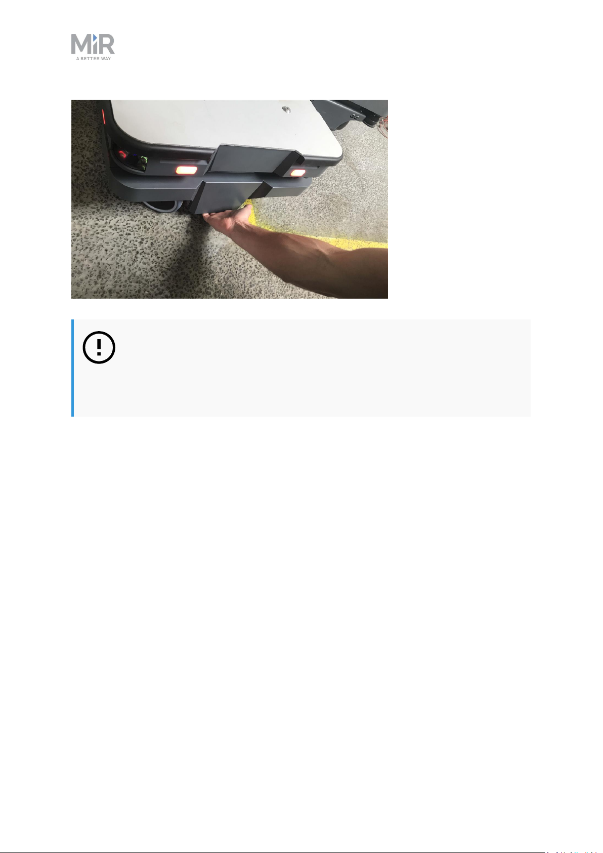
5. Drive the robot off the ramp using the joystick.
Place your foot in front of the ramp while the robot drives on it to keep the
ramp from slipping.
MiR250 Shelf Carrier User Guide (en) 03/2021 - v.1.4 ©Copyright 2021: Mobile IndustrialRobots A/S. 61
Page 62

6. Getting started
6.7 Moving the robot by hand
You should generally avoid moving the robot by hand, but if, for example, the robot gets
stuck near an obstacle and cannot be moved by manual control, it is possible to do so.
Before moving the robot by hand, make sure the mechanical brakes are released.
To release the brakes, the robot must be turned on—see Connecting the
battery on page53. When the robot shuts down due to low battery, there is
still enough power to use the manual brake release for a week or more.
MiR250 Shelf Carrier User Guide (en) 03/2021 - v.1.4 ©Copyright 2021: Mobile IndustrialRobots A/S. 62
Page 63

6. Getting started
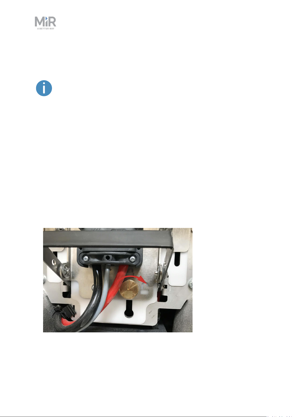
Release the brakes by turning the Manual brake release switch located below the control
panel clockwise.
Figure 6.2. The Manual brake release switch is located below the control panel.
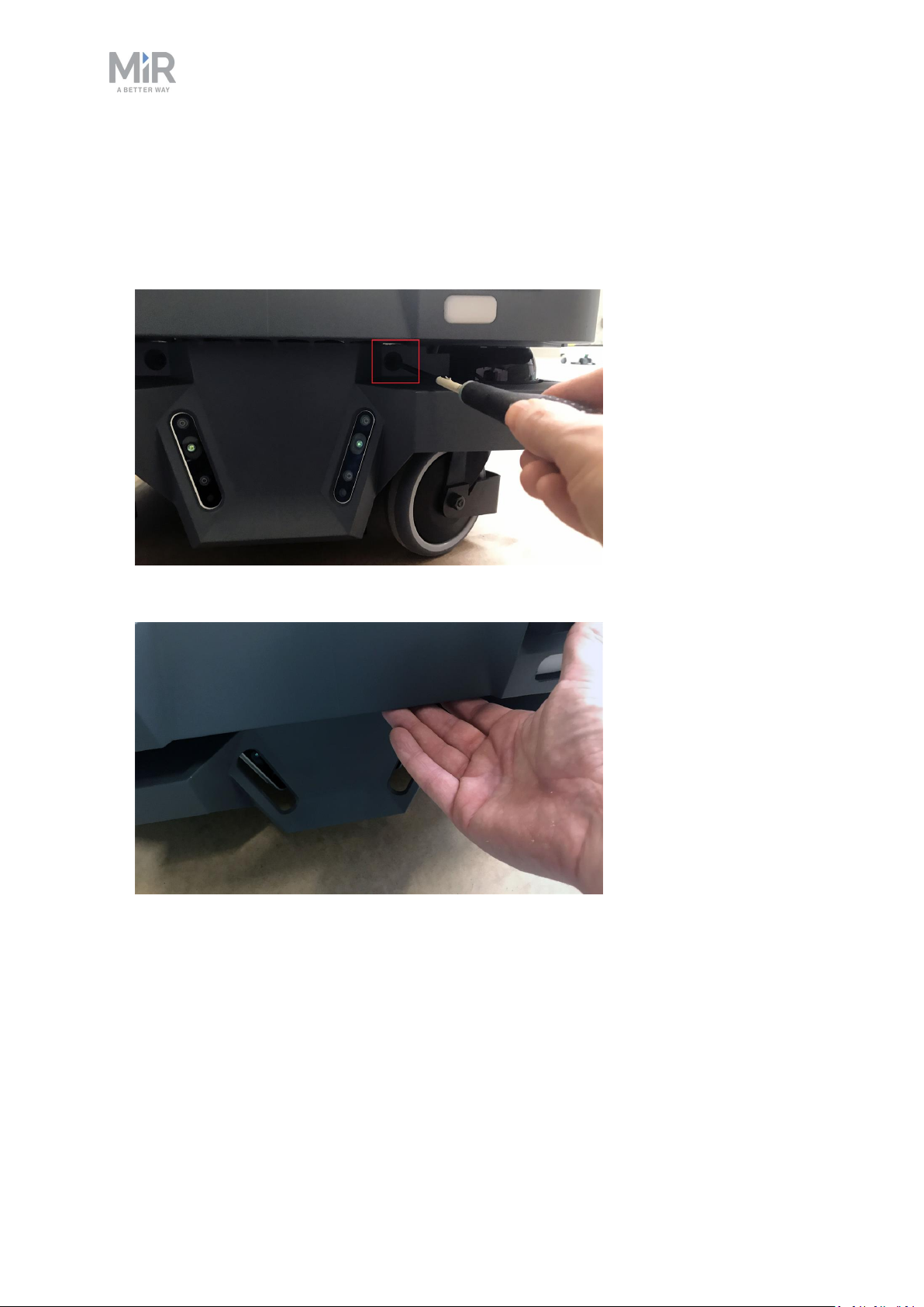
To move the robot by hand, either push or pull it.
When pushing or pulling the robot, grip the MiR Shelf Carrier 250 top module.
You can also pull the robot using the designated pull handles beneath the front and rear
covers.
MiR250 Shelf Carrier User Guide (en) 03/2021 - v.1.4 ©Copyright 2021: Mobile IndustrialRobots A/S. 63
Page 64
6. Getting started
NOTICE
When handling the robot, do not push or pull the robot sideways, and do not
use the covers for pushing or pulling. Only use the designated pull handles or
the top module.
6.8 Checking the hardware status
To check that all hardware components work as intended, follow these steps:
1. Sign in to the robot interface—see Connecting to the robot interface on page58.
2. Go to Monitoring > Hardware health.
MiR250 Shelf Carrier User Guide (en) 03/2021 - v.1.4 ©Copyright 2021: Mobile IndustrialRobots A/S. 64
Page 65
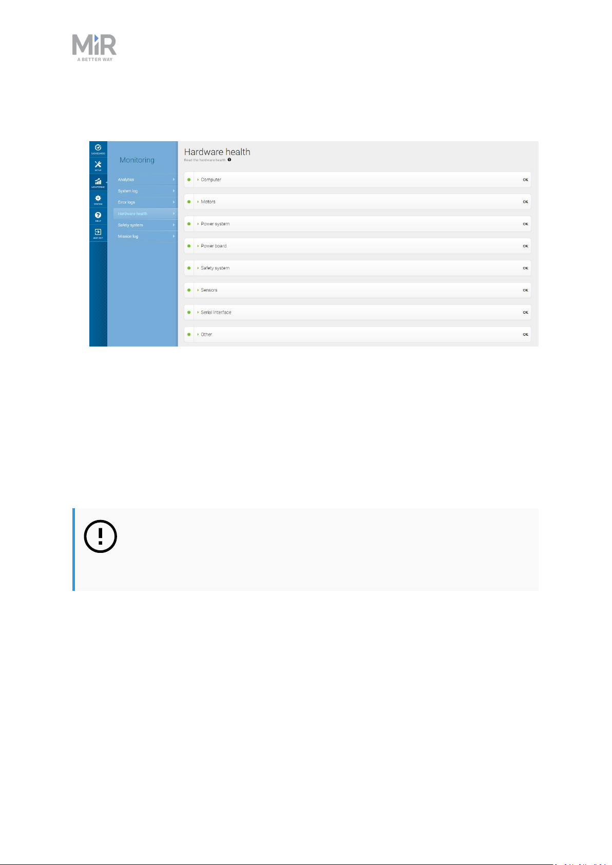
6. Getting started
3. Check that all elements on the page have the OK status and that they have green dots on
the left.
For more information, see Hardware health in MiR Robot Reference Guide on the MiR
website.
6.9 Mounting the nameplate
Before using MiR250 Shelf Carrier, you must mount its unique nameplate to it. The
nameplate contains information specific to your MiR application—see Nameplate on
page16.
NOTICE
The nameplate must be mounted as described in the following steps. If
mounted incorrectly, the CEmark is invalid.
MiR250 Shelf Carrier User Guide (en) 03/2021 - v.1.4 ©Copyright 2021: Mobile IndustrialRobots A/S. 65
Page 66

To mount the nameplate correctly, follow these steps:
1. Locate the rear cover—see External parts on page13.
2. Clean the area marked in the image below with a degreasing agent.
6. Getting started
3. Mount the nameplate on the cleaned area.
MiR250 Shelf Carrier User Guide (en) 03/2021 - v.1.4 ©Copyright 2021: Mobile IndustrialRobots A/S. 66
Page 67

6. Getting started
6.10 Enable the MiR250 Shelf Carrier feature
To access the MiR250 Shelf Carrier settings and mission menus, the MiR250 Shelf Carrier
features must be enabled.To check that they are enabled, follow these steps:
1. Sign in to the robot interface, and go to System > Settings > Features.
MiR250 Shelf Carrier User Guide (en) 03/2021 - v.1.4 ©Copyright 2021: Mobile IndustrialRobots A/S. 67
Page 68

2. Under ShelfPallet Lift and Shelf, select True.
6. Getting started
3. Under I/O modules, select True. The MiR Shelf Carrier 250 top module communicates
with the robot through I/O modules, so they must be activated for the shelf carrier to
work.
MiR250 Shelf Carrier User Guide (en) 03/2021 - v.1.4 ©Copyright 2021: Mobile IndustrialRobots A/S. 68
Page 69

6. Getting started
6.11 Testing the top module
To test that the top module of MiR250 Shelf Carrier is configured and connected correctly,
follow these steps:
1. Sign in to the robot interface, and go to Setup > I/O modules.
MiR250 Shelf Carrier User Guide (en) 03/2021 - v.1.4 ©Copyright 2021: Mobile IndustrialRobots A/S. 69
Page 70

6. Getting started
2. Under MiR internal I/Os, complete the following sequence, and verify that the robot
executes the expected action:
a. Under Outputs, select 3. Verify that the carrier pins rise up.
b. Once the pins are raised, verify that 3 under Inputs is green.
c. Under Outputs, select 2. Verify that the carrier pins lower into the robot.
MiR250 Shelf Carrier User Guide (en) 03/2021 - v.1.4 ©Copyright 2021: Mobile IndustrialRobots A/S. 70
Page 71

6. Getting started
d. Once the pins are lowered, verify that 2 under Inputs is green.
If the lift was raised and lowered as expected and the correct input feedback was received,
MiR Shelf Carrier 250 is correctly installed.
If MiR Shelf Carrier 250 did not operate correctly, verify that you have enabled the feature
as described in Enable the MiR250 Shelf Carrier feature on page67. If MiR Shelf Carrier 250
continues to fail, contact your distributor.
6.12 Shutting down the robot
To shut down MiR250 Shelf Carrier, follow these steps:
1. Ensure that the robot is not moving or executing an action.
2. Press the Power button for three seconds.
MiR250 Shelf Carrier User Guide (en) 03/2021 - v.1.4 ©Copyright 2021: Mobile IndustrialRobots A/S. 71
Page 72

6. Getting started
3. The robot starts the shutdown process. The status lights waver yellow, and the Power
button blinks red.
4. When the robot finishes the shutdown process, the status and the signal lights go off, and
the Power button turns blue.
When you shut down the robot for transportation, service, or repair, the battery must be
disconnected—see Disconnecting the battery on page74.
MiR250 Shelf Carrier User Guide (en) 03/2021 - v.1.4 ©Copyright 2021: Mobile IndustrialRobots A/S. 72
Page 73

7. Battery and charging
7. Battery and charging
The robot is powered by a fast swap lithium-ion battery that can be charged inside the robot
with a MiR cable charger or a MiR Charge48V charging station.
7.1 Charging the robot
This section describes how to charge MiR250 Shelf Carrier using a MiR cable charger.
A MiR cable charger is not part of the MiR250 Shelf Carrier standard delivery.
Contact your distributor for more information.
The robot is delivered 40-60% charged.
The rear compartment holds the robot’s battery. To access the rear compartment, see
Accessing the internal parts on page43.
To charge MiR250 Shelf Carrier using the cable charger, connect the cable charger to the
charging interface on the robot in the bottom-right corner.
Use only an original MiR cable charger.
MiR250 Shelf Carrier User Guide (en) 03/2021 - v.1.4 ©Copyright 2021: Mobile IndustrialRobots A/S. 73
Page 74
7. Battery and charging
If the robot has been inactive for more than a week or if its battery
percentage has been below 5% for more than four hours, the battery goes into
Power save mode, which disables the power to the robot—see Battery storage
on page79.
To disable Power save mode, disconnect the battery connector for 30 seconds
and then reconnect it and wait 30 seconds before turning on the robot, or
connect a MiR cable charger to the robot.
For information about the charging time, see specifications on the MiR website.
7.2 Disconnecting the battery
Whenever the robot is to be transported, undergo maintenance, or stored for long periods of
time, you should always disconnect the battery.
The rear compartment holds the robot’s battery. To access the rear compartment, see
Accessing the internal parts on page43.
To disconnect the battery, follow these steps:
1. Turn the battery lock clockwise to release it.
MiR250 Shelf Carrier User Guide (en) 03/2021 - v.1.4 ©Copyright 2021: Mobile IndustrialRobots A/S. 74
Page 75

2. Press down on the battery lever to disconnect the battery.
3. Turn the battery lock counterclockwise to lock it.
7. Battery and charging
7.3 Enabling fast swap
If you wish to enable the fast swap-option on the robot, you must modify the battery
disconnect assembly.
The levers holding the battery in place are fastened with screws from the
factory to ensure that the battery stays disconnected during transportation.
The rear compartment holds the robot’s battery. To access the rear compartment, see
Accessing the internal parts on page43.
MiR250 Shelf Carrier User Guide (en) 03/2021 - v.1.4 ©Copyright 2021: Mobile IndustrialRobots A/S. 75
Page 76

7. Battery and charging
To enable the fast swap-option on the robot, follow these steps:
1. Disconnect the battery—see Disconnecting the battery on page74.
2. Unscrew the screw shown in the image below with a T20 Torx screwdriver. Do this on
both sides of the lever.
3. Unscrew the screw shown in the image below with a 10 mm Hex screwdriver. Do this on
both sides of the lever.
MiR250 Shelf Carrier User Guide (en) 03/2021 - v.1.4 ©Copyright 2021: Mobile IndustrialRobots A/S. 76
Page 77
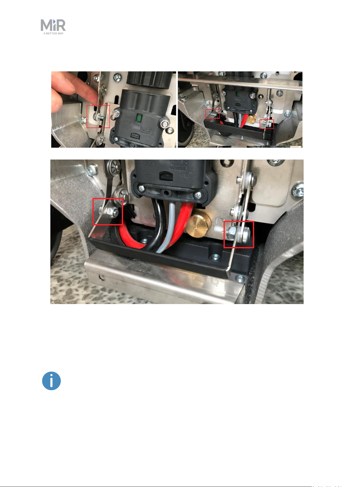
4. Fasten the two levers to the lever controlling the connector.
7. Battery and charging
7.4 Swapping out the lithium-ion battery
MiR250 Shelf Carrier is supplied with a removable lithium-ion battery. The battery can be
charged inside the robot with a MiR cable charger.
The robot is delivered with one lithium-ion battery. Contact your distributor if
you need more batteries.
MiR250 Shelf Carrier User Guide (en) 03/2021 - v.1.4 ©Copyright 2021: Mobile IndustrialRobots A/S. 77
Page 78

7. Battery and charging
To be able to remove the battery, you must first enable the fast swap-option in your robot—
see Enabling fast swap on page75.
The rear compartment holds the robot’s battery. To access the rear compartment, see
Accessing the internal parts on page43.
To swap out the battery, follow these steps:
1. Disconnect the battery—see Disconnecting the battery.
2. Pull out the battery.
You can now replace the battery.
3. Do these steps in reverse when putting in the battery.
MiR250 Shelf Carrier User Guide (en) 03/2021 - v.1.4 ©Copyright 2021: Mobile IndustrialRobots A/S. 78
Page 79

7. Battery and charging
7.5 Battery storage
The battery should be stored in an area at room temperature with a non-condensing relative
air humidity—see specifications on the MiR website. Temperatures and humidity below or
above the specifications will shorten the service life of the battery.
The battery should not be exposed to nor submerged in any liquid as this may damage the
battery.
Charge the battery before storage to preserve the service life of the battery.
NOTICE
If you store the battery for a longer period of time when it is almost depleted,
you may not be able to get it running again. Contact your distributor if this
occurs.
To preserve the battery, disconnect the battery from the robot before storing the robot.
Power save mode
If the battery is not used for a period of time, it enters Power save mode. When the battery
is in Power save mode, it will not power the robot until the battery is activated again.
To activate the battery after it has been in Power save mode, disconnect it from the robot
for 30 seconds, reconnect it to the robot, wait 30 seconds, and then turn on the robot. If the
robot cannot turn on, contact your distributor.
The amount of time it takes for the battery to enter Power save mode depends on the state
of charge of the battery. The best state to store the battery at is when it is 80% charged.
Table 7.1 provides best practice values for storage time and the time it takes for the battery
to enter Power save mode depending on the battery percentage.
Table 7.1.
Time taken for the battery to enter Power save mode and maximum storage time at
various battery percentages
Battery state of charge Power save mode timeout Maximum storage time
100% 1 week 18 months
MiR250 Shelf Carrier User Guide (en) 03/2021 - v.1.4 ©Copyright 2021: Mobile IndustrialRobots A/S. 79
Page 80

7. Battery and charging
Battery state of charge Power save mode timeout Maximum storage time
75% 1 week 15 months
50% 1 week 12 months
25% 1 week 6 months
5% 4 hours 2 months
0% 4 hours 1 month
The battery percentage displayed in the robot interface is based on when the
robot will shut down due to low voltage. When the interface displays 0%
battery percentage, the actual state of charge is around 5%
Deep sleep
When the battery is completely depleted, the battery enters Deep sleep mode. It can be
stored for six weeks in this state before the battery shuts down completely, and the battery
cells may begin to take damage.
When you connect the battery to a charger, it should be brought out of Deep sleep mode,
but if not, apply the same method as when it goes into Power save mode.
7.6 Battery disposal
Return unserviceable batteries to relevant facilities in accordance with local statutory
regulations.
A crossed-out wheeled bin indicates that the product needs to be disposed separately and
not as municipal waste—see Figure 7.1.
You are legally obliged to return used batteries and rechargeable batteries. Disposing used
batteries in the household waste is prohibited. Batteries containing hazardous substances are
marked with the crossed-out wheeled bin. The symbol indicates that it is forbidden to
dispose the product via the domestic refuse. The chemical symbols for the respective
hazardous substances are Cd= Cadmium, Hg = Mercury, Pb = Lead.
MiR250 Shelf Carrier User Guide (en) 03/2021 - v.1.4 ©Copyright 2021: Mobile IndustrialRobots A/S. 80
Page 81

Figure 7.1. Battery disposal symbols.
7. Battery and charging
MiR250 Shelf Carrier User Guide (en) 03/2021 - v.1.4 ©Copyright 2021: Mobile IndustrialRobots A/S. 81
Page 82

8. IT security
8. IT security
ITsecurity is a set of precautions you can take to prevent unauthorized personnel from
accessing MiR250 Shelf Carrier. This section describes the main IT-security related risks and
how to minimize them when commissioning MiR250 Shelf Carrier.
MiR250 Shelf Carrier communicates all data over the network that it is connected to. It is
the responsibility of the commissioner to ensure that it is connected to a secure network.
MiR recommends conducting an IT-security risk assessment before commissioning the robot.
Contact your distributor for a list of FAQs about IT security.
8.1 Managing users and passwords
Managing your users and passwords is the main way you can control access to MiR250 Shelf
Carrier.
There are three default users with predefined passwords for you to start using. These are
described in the MiR Robot Reference Guide along with instructions to create new users,
user groups, and passwords. MiR advises you to:
• Change the default password for all predefined users if you choose to continue to use
them. Make sure to choose a strong password since MiR250 Shelf Carrier does not
enforce any password rules nor expire the password.
• Create new user groups if more levels of access are necessary.
• Create dedicated user accounts under the relevant user group for each person accessing
MiR250 Shelf Carrier, and ensure that the users change the password on their first signin. It is not recommended to have several users share the same account.
• Only enable users with a minimum level of access to use a pin code to sign in. Users with
a higher level of access are recommended to use a strong password to sign in instead.
8.2 Software security patches
To improve the security of MiR250 Shelf Carrier, MiR supplies security patches to the
operating system in new MiR software update files. When you install a security patch, it
takes approximately 10-15 minutes longer to update a MiR product.
MiR250 Shelf Carrier User Guide (en) 03/2021 - v.1.4 ©Copyright 2021: Mobile IndustrialRobots A/S. 82
Page 83

8. IT security
Understanding MiR software versions
MiR uses the Major.Minor.Patch.Hot fix format to version software. For example, 2.8.1.1
means that the software is based on the second major release, the eighth minor release of
the major version, the first patch release of the minor version, and, in this example, a single
hot fix is included too.
• Major releases include the most significant changes that affect the entire robot software.
• Minor releases often include new features and smaller changes that only affect parts of
the software.
• Patch releases focus on fixing small issues in the software and introducing quality
improvements.
• Hot fix releases are only created when a patch release has introduced a critical issue that
needs to be fixed immediately.
Security patch policy
MiR applies the following policy when supplying security patches:
• New security patches are distributed per every minor release.
• All patch releases under a minor release include the previous security patches also. In
other words, if you chose not to install the first software version in a minor release, such
as version 2.9.0, the security patches will still be installed when you update to 2.9.1 or
higher.
MiR250 Shelf Carrier User Guide (en) 03/2021 - v.1.4 ©Copyright 2021: Mobile IndustrialRobots A/S. 83
Page 84

9. Navigation and control system
9. Navigation and control system
The navigation and control system is responsible for driving the robot to a goal position
while avoiding obstacles. This section describes the processes and components involved in
the robot's navigation and control system.
9.1 System overview
The purpose of the navigation and control system is to guide the robot from one position on
a map to another position. The user provides the map and chooses the goal position the
robot must move to. The diagram in Figure 9.1 describes the processes in the navigation and
control system.
The main processes involved in the navigation system are:
• Global planner
The navigation process starts with the global planner determining the best path for the
robot to get from its current position to the goal position. It plans the route to avoid walls
and structures on the map.
• Local planner
While the robot is following the path made by the global planner, the local planner
continuously guides the robot around detected obstacles that are not included on the
map.
• Obstacle detection
The safety laser scanners, 3D cameras, and proximity sensors are used to detect obstacles
in the work environment. These are used to prevent the robot from colliding with
obstacles.
• Localization
This process determines the robot's current position on the map based on input from the
motor encoders, inertial measurement unit(IMU), and safety laser scanners.
• Motor controller and motors
The motor controller determines how much power each motor must receive to drive the
robot along the intended path safely. Once the robot reaches the goal position, the brakes
are engaged to stop the robot.
Each part of the process is described in greater detail in the following sections.
MiR250 Shelf Carrier User Guide (en) 03/2021 - v.1.4 ©Copyright 2021: Mobile IndustrialRobots A/S. 84
Page 85

9. Navigation and control system
Figure 9.1. Flow chart of the navigation and control system. The user provides the necessary input for the robot
to generate a path to the goal position. The robot executes the steps in the navigation loop until it reaches the
goal position and stops by engaging the brakes.
MiR250 Shelf Carrier User Guide (en) 03/2021 - v.1.4 ©Copyright 2021: Mobile IndustrialRobots A/S. 85
Page 86

9. Navigation and control system
9.2 User input
To enable the robot to navigate autonomously, you must provide the following:
• A map of the area, either from a .png file or created with the robot using the mapping
function—see Creating and configuring maps on page124.
• A goal destination on that map—see Markers on page135.
• The current position of the robot on the map. This usually only needs to be provided when
a new map is activated.
Figure 9.2. On the map, the current position of the robot is identified by the robot icon , and the goal
destination in this example is the robot position . The robot computer now determines a path from the
current position to the goal position.
Once the robot computer has a map with the robot's current position and a goal destination,
it begins planning a route between the two positions on the map using the global planner.
9.3 Global planner
The global planner is an algorithm in the robot computer that generates a path to the goal
position.This path is known as the global path.
MiR250 Shelf Carrier User Guide (en) 03/2021 - v.1.4 ©Copyright 2021: Mobile IndustrialRobots A/S. 86
Page 87

9. Navigation and control system
Figure 9.3. The global path is shown with the blue dotted line that leads from the start to the goal position.
The global path is created only at the start of a move action or if the robot has failed to
reach the goal position and needs to create a new path. The generated path only avoids the
obstacles the robot detected when the path was made and the obstacles marked on the map.
The global path can be seen in the robot interface as a dotted line from the robot's start
position to the goal position.
Figure 9.4. The dotted line from the start position of the robot to the goal position is the global path generated
by the robot computer.
MiR250 Shelf Carrier User Guide (en) 03/2021 - v.1.4 ©Copyright 2021: Mobile IndustrialRobots A/S. 87
Page 88

9. Navigation and control system
9.4 Local planner
The local planner is used continuously while the robot is driving to guide it around obstacles
while still following the global path.
Figure 9.5. The global path is indicated with the dotted blue line and is visible on the map. The local path is
indicated with the blue arrow, showing the robot driving around a dynamic obstacle.
Whereas the global planner creates a single path from start to finish, the local planner
continues to create new paths that adapt to the current position of the robot and the
obstacles around it. The local planner only processes the area that is immediately
surrounding the robot, using input from the robot sensors to avoid obstacles.
The local path is not displayed in the robot interface. The arrows in the images
here are visual aids used in this guide only.
MiR250 Shelf Carrier User Guide (en) 03/2021 - v.1.4 ©Copyright 2021: Mobile IndustrialRobots A/S. 88
Page 89

9. Navigation and control system
Figure 9.6. The local planner usually follows the global planner, but as soon as an obstacle gets in the way, the
local planner determines which immediate path will get the robot around the obstacle. In this case, it will likely
choose the path indicated with a green arrow.
Once the local path is determined, the robot computer derives the desired rotational
velocity of each drive wheel to make the robot follow the local path and sends the desired
velocities for each motor to the motor controllers—see Motor controller and motors on
page97.
9.5 Obstacle detection
The robot detects obstacles continuously while driving. This enables the robot to use the
local planner to drive around obstacles and to determine the robot's current position on the
map.
Three sensor types are responsible for detecting obstacles:
• The safety laser scanners
• The 3D cameras
• The proximity sensors
MiR250 Shelf Carrier User Guide (en) 03/2021 - v.1.4 ©Copyright 2021: Mobile IndustrialRobots A/S. 89
Page 90
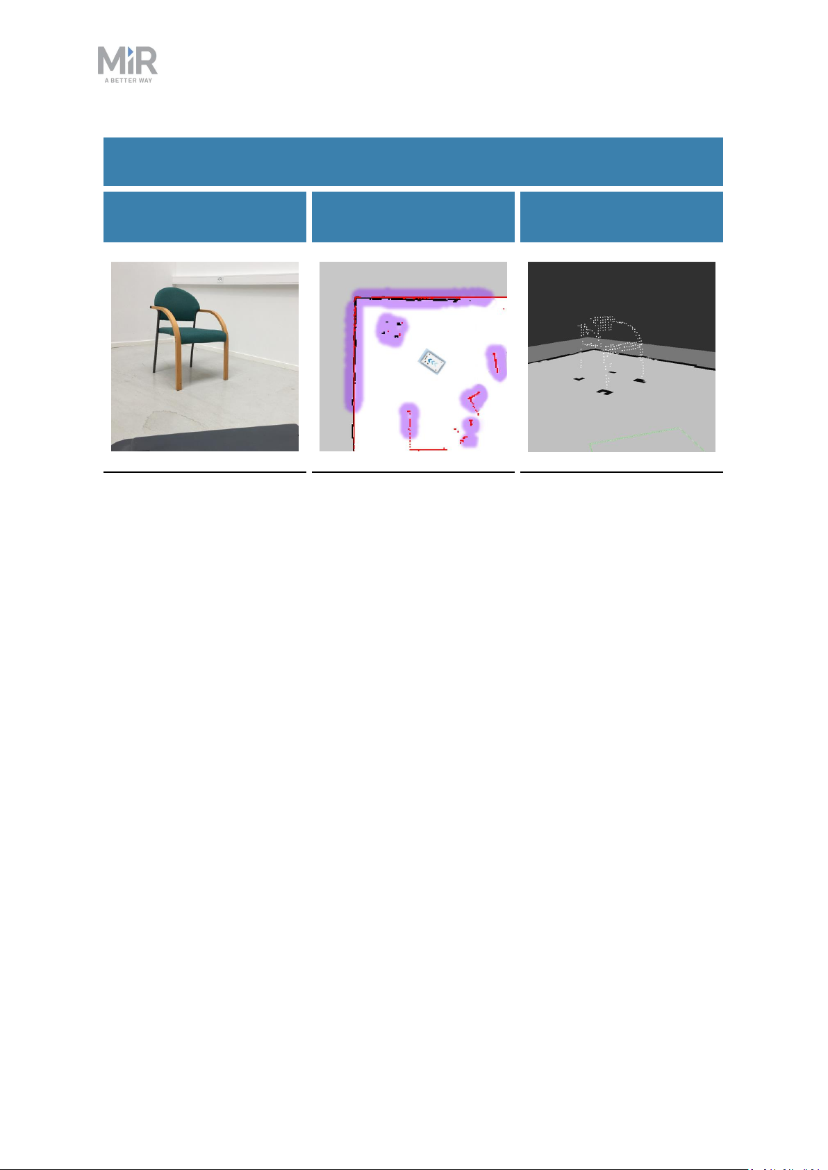
9. Navigation and control system
Table 9.1.
Description of how the robot sees obstacles with its sensors
What a human sees
A chair placed in the
corner of a room is
detectable by the robot.
What the laser scanners
see
In the robot interface, the
red lines on a map are
obstacles detected by the
laser scanners, and the
purple clouds are an
aggregate of the 3D
camera and laser scanner
data. The scanners only
detect the four legs of the
chair.
What the 3D cameras see
The 3D cameras detect
more details of the chair
when the robot gets close
enough to it.This view
cannot be seen in the robot
interface.
Safety laser scanners
Two safety laser scanners, diagonally placed on one front and one rear corner of the robot,
scan their surroundings. Each safety laser scanner has a 270° field of view, overlapping and
thus providing a full 360° visual protection around the robot.
When in motion, the safety laser scanners continuously scan the surroundings to detect
objects.
MiR250 Shelf Carrier User Guide (en) 03/2021 - v.1.4 ©Copyright 2021: Mobile IndustrialRobots A/S. 90
Page 91

9. Navigation and control system
Figure 9.7. The two safety laser scanners together provide a full 360° view around the robot.
The laser scanners have the following limitations:
• They can only detect objects that intersect a plane at 200 mm height from the floor.
• They do not detect transparent obstacles well.
• The scanner data can be inaccurate when detecting reflective obstacles.
• The laser scanners may detect phantom obstacles if they are exposed to strong direct
light.
If you are using the robot in an area with walls made of glass or reflective
material, mark the walls as Forbidden zones on the map, not as walls—see
Creating and configuring maps on page124. Walls on the map that the
robot cannot detect will confuse the robot's navigation system.
3Dcameras
Two 3D cameras positioned on the front of the robot detect objects in front of the robot. The
3D cameras detect objects:
• Vertically up to 1800 mm at a distance of 1200 mm in front of the robot.
• Horizontally in an angle of 114° and 250 mm to the first view of ground.
MiR250 Shelf Carrier User Guide (en) 03/2021 - v.1.4 ©Copyright 2021: Mobile IndustrialRobots A/S. 91
Page 92

9. Navigation and control system
The 3D cameras are only used for navigation. They are not part of the robot's safety system.
The camera readouts are used as 3D point cloud data. They are not recording
recognizable objects or people.
Figure 9.8. The two 3D cameras can see objects up to 1800 mm above floor height at a distance of 1200 mm in
front of the robot and have a horizontal field of view of 114°.
MiR250 Shelf Carrier User Guide (en) 03/2021 - v.1.4 ©Copyright 2021: Mobile IndustrialRobots A/S. 92
Page 93

9. Navigation and control system
The 3D cameras have the following limitations:
• They can only detect objects in front of the robot, unlike the full 360° view of the laser
scanners.
• They do not detect transparent or reflective obstacles well.
• They do not detect holes or decending stairways.
• The cameras are not reliable at determining depth when viewing structures with
repetitive patterns.
• The cameras may detect phantom obstacles if they are exposed to strong direct light.
Proximity sensors
Proximity sensors placed in all four corners of the robot detect objects close to the floor that
cannot be detected by the safety laser scanners.
Using infrared light, the proximity sensors point downwards and make sure that the robot
does not run into low objects, such as pallets and forklift forks. They have a range between
5-20 cm around the robot.
Because of the proximity sensor's limited range, the data from them is only useful when the
robot is standing still or moving at reduced speeds, for example, when the robot it pivoting
or docking.
Figure 9.9. The proximity sensors in the corners of the robot detect objects below the safety laser scanners'
plane of view.
MiR250 Shelf Carrier User Guide (en) 03/2021 - v.1.4 ©Copyright 2021: Mobile IndustrialRobots A/S. 93
Page 94

9. Navigation and control system
The proximity sensors have the following limitations:
• They do not have a long range and are mainly used to detect obstacles missed by the
laser scanners and cameras.
• When the robot is driving fast, obstacles detected by the proximity sensors are too close
for the robot to stop for or avoid.
9.6 Localization
The goal of the localization process is for the robot to determine where it is currently
located on its map. The robot has three inputs for determining where it is:
• The initial position of the robot. This is used as a reference point for the methods used to
determine the robot position.
• The IMUand encoder data. This is used to determine how far and fast the robot has
traveled from the initial position.
• The laser scanner data. This is used to determine the likely positions of the robot by
comparing the data with nearby walls on the map.
This data is used by a particle filter to determine the most likely position of the robot on the
map.
IMUand motor encoders
Both the data from the IMU (Inertial Measurement Unit) and motor encoders is used to
derive where and how fast the robot has traveled over time from its initial position. The
combination of both sets of data makes the derived position more accurate.
If the drive wheels are worn down significantly—see Maintenance on
page220—or the robot is running with an incorrect gear ratio, the robot will
miscalculate how far it has traveled based on the encoder data.
Laser scanners and particle filtering
The robot computer compares the input from the laser scanners with the walls on the map
to try and find the best match. This is done using a particle filter algorithm. The robot
computer only compares input from the area where it expects the robot to be based on the
encoder and IMUdata. Therefore, it is important that the initial position of the robot is
correct.
MiR250 Shelf Carrier User Guide (en) 03/2021 - v.1.4 ©Copyright 2021: Mobile IndustrialRobots A/S. 94
Page 95

9. Navigation and control system
Failed localization Successful localization
Figure 9.10. In a failed localization, the robot cannot determine a position where the red lines (laser scanner
data) align with the black lines on the map. When the robot can localize itself, it determines a cluster of likely
positions, indicated in the images above as blue dots.
To make sure the robot can localize itself well using particle filtering, consider the following
when creating a map.
• There must be unique and distinguishable static landmarks on the map that are easily
recognizable. A landmark is a permanent structure that the robot can use to orient itself,
such as corners, doorways, columns, and shelves.
No distinguishable landmarks Many distinguishable landmarks
MiR250 Shelf Carrier User Guide (en) 03/2021 - v.1.4 ©Copyright 2021: Mobile IndustrialRobots A/S. 95
Page 96

9. Navigation and control system
• The robot must be able to detect the static landmarks that are marked on the map to be
able to approximate its current position. Make sure there are not too many dynamic
obstacles around the robot so that it cannot detect any static landmarks.
Cannot detect any static landmarks Can detect enough static landmarks
• To improve the robot's localization, it can often help to divide long continuous walls on
the map. Even if the walls are connected in the actual work environment, it can help the
localization process if the walls on the map are divided into smaller sections.
Undivided walls Divided walls
MiR250 Shelf Carrier User Guide (en) 03/2021 - v.1.4 ©Copyright 2021: Mobile IndustrialRobots A/S. 96
Page 97

9. Navigation and control system
• The robot does not compare the laser scanner data with the entire map, but only around
the area that it expects to be close to based on the IMU and encoder data and its initial
position. This is why it is important that the initial position you place the robot at on the
map is accurate.
• The robot can drive for a short distance without being correctly localized. As it drives, the
estimated positions should converge to a small area, indicating the robot has determined
an accurate estimate. If this does not occur within a set time limit, the robot reports a
localization error.
9.7 Motor controller and motors
The robot keeps adjusting how much power is sent to each motor based on sensory
input.This means the robot can correct its speed when going up slopes or when carrying a
heavier payload, and it can change its driving direction to avoid moving obstacles.
9.8 Brakes
Once the approximated position of the robot determined from localization is the same as the
goal position calculated by the global planner, the robot stops by using the dynamic brake
function.
Figure 9.11. The robot has reached the goal position and stops by engaging the dynamic brake function.
The dynamic brake function stops the robot by short circuiting the power that was used to
rotate the motor. When this happens, the power that was used to drive the robot forward is
now reversed to stop the rotation of the drive wheels.
MiR250 Shelf Carrier User Guide (en) 03/2021 - v.1.4 ©Copyright 2021: Mobile IndustrialRobots A/S. 97
Page 98

9. Navigation and control system
Once the robot has stopped, the mechanical brakes are enabled. These brakes are used to
keep the robot in place once it has stopped. You can compare the mechanical brakes with
the parking brake or hand brake in a car.
The mechanical brakes are only used to stop the robot when it is in motion in
emergency situations triggered by the safety system.
The mechanical brakes are automatically released again when the robot receives a new
order requiring it to move.
MiR250 Shelf Carrier User Guide (en) 03/2021 - v.1.4 ©Copyright 2021: Mobile IndustrialRobots A/S. 98
Page 99

10. Safety system
10. Safety system
The robot's safety system is designed to mitigate significant hazards which could lead to
injury, for example, stopping the robot if a person is in its path.
MiR250 Shelf Carrier is equipped with a range of built-in safety-related functions. Each
safety function is designed according to the standard ISO 13849-1. The safety-related
functions are selected to support compliance with EN 1525 and ISO 3691-4.
10.1 System overview
The safety system is controlled mainly by the safety PLC. The PLCregulates inputs and
outputs from safety-related functions or interfaces involved with ensuring the safety of
personnel working nearby the robot.
If a safety function is triggered, the robot uses its STO(Safe Torque Off) contactors to bring
the robot to a category 0 stop (stopping by “immediate removal of power to the machine
actuators" according to IEC 60204-1) followed by a controlled brake using an SS1 (Safe Stop
1) function. This is known as bringing the robot into Emergency stop or Protective stop,
depending on the function—see Types of stop below.
Types of stop
There are four different stopped states:
• Operational stop
• Protective stop
• Emergency stop
• Manual stop
The last three types of stop are monitored by the safety PLC.
Operational stop
The robot is in Operational stop when it is stopped through the robot interface either
through a mission action or by pausing the mission. The top module and all moving parts are
still connected to a power supply.
MiR250 Shelf Carrier User Guide (en) 03/2021 - v.1.4 ©Copyright 2021: Mobile IndustrialRobots A/S. 99
Page 100

10. Safety system
Protective stop
The robot enters Protective stop automatically to ensure the safety of nearby personnel.
When the robot enters Protective stop, internal safety contactors are switched so the robot's
top module and all moving parts of the robot do not receive power. You can hear the safety
contactors emit audible clicks when they are switched.
When the robot is in Protective stop, the status lights of the robot turn red, and you are not
able to move the robot or send it on missions until you bring the robot out of the Protective
stop. The following cases describe the various Protective stops and how to bring the robot
out of them:
• A safety laser scanner detects an object in its active Protective field
Remove the object from the active Protective field—see Personnel detection on page104.
The robot will resume its operating state after two seconds.
• The robot finishes the startup process
The Resume button will flash after startup. Press the flashing Resume button to bring the
robot out of Protective stop.
• Switching between Manual mode and Autonomous mode
After turning the Operating mode key to switch operating modes, the robot enters
Protective stop, and the Resume button flashes. Press the Resume button to bring the
robot out of Protective stop.
• The safety system detects a fault, or the motor control system detects a discrepancy
To bring the robot out of Protective stop, resolve the fault causing the error. Use
information regarding the error from the robot interface to determine the fault. Go to
Monitoring > Hardware health to find specific information on what caused the issue. For
further guidance, see the troubleshooting guides on the Distributor site.
Emergency stop
The robot enters Emergency stop when an Emergency stop button has been pressed
physically. When you press the Emergency stop button, internal safety contactors are
switched so the robot's top application and all moving parts of the robot do not receive
power. You can hear the safety contactors emit audible clicks when they are switched.
When the robot is in Emergency stop, the status lights of the robot turn red, and you are not
able to move the robot or send it on missions until you bring the robot out of the Emergency
stop. To do this, you must release the Emergency stop button and then press the Resume
MiR250 Shelf Carrier User Guide (en) 03/2021 - v.1.4 ©Copyright 2021: Mobile IndustrialRobots A/S. 100
 Loading...