


User Guide (en)
Date: 12/2020
Revision: v.1.4

Copyright and disclaimer
All rights reserved. No parts of this document may be reproduced in any form without the
express written permission of Mobile Industrial Robots A/S (MiR). MiR makes no warranties,
expressed or implied, in respect of this document or its contents. In addition, the contents of
the document are subject to change without prior notice. Every precaution has been taken in
the preparation of this document. Nevertheless, MiR assumes no responsibility for errors or
omissions or any damages resulting from the use of the information contained.
Copyright © 2019-2020 by Mobile Industrial Robots A/S.
Contact the manufacturer:
Mobile Industrial Robots A/S
Emil Neckelmanns Vej 15F
DK-5220 Odense SØ
www.mobile-industrial-robots.com
Phone: +45 20 377 577
Email: support@mir-robots.com
CVR: 35251235
MiR1000User Guide (en) 12/2020 - v.1.4 ©Copyright 2019-2020: Mobile IndustrialRobots A/S. 2

Table of contents
1. About this document 8
1.1 Where to find more information 8
1.2 Version history 9
2. Product presentation 10
2.1 Main features of MiR1000 11
2.2 Top modules 12
2.3 External parts 13
2.4 Internal parts 19
2.5 Manual brake release switch 25
3. Warranty 26
4. Accessing the internal parts 27
4.1 Front compartment 27
4.2 Rear compartment 29
4.3 Side compartments 29
4.4 Top compartments 30
5. Safety 31
5.1 Safety message types 31
5.2 General safety precautions 32
5.3 Intended use 35
5.4 Users 37
5.5 Foreseeable misuse 38
5.6 Residual risks 38
6. Getting started 40
MiR1000User Guide (en) 12/2020 - v.1.4 ©Copyright 2019-2020: Mobile IndustrialRobots A/S. 3

6.1 In the box 40
6.2 Unpacking MiR1000 41
6.3 Connecting the battery 45
6.4 Powering up the robot 46
6.5 Connecting to the robot interface 48
6.6 Driving the robot in Manual mode 50
6.7 Checking the hardware status 52
6.8 Mounting the nameplate 53
6.9 Shutting down the robot 55
7. Battery and charging 56
7.1 Charging the robot 56
7.2 Disconnecting the battery 57
7.3 Battery storage 57
7.4 Battery disposal 58
8. IT security 59
8.1 Managing users and passwords 59
8.2 Software security patches 59
9. Navigation and control system 61
9.1 System overview 61
9.2 User input 63
9.3 Global planner 63
9.4 Local planner 65
9.5 Obstacle detection 66
9.6 Localization 72
MiR1000User Guide (en) 12/2020 - v.1.4 ©Copyright 2019-2020: Mobile IndustrialRobots A/S. 4

9.7 Motor controller and motors 75
9.8 Brakes 75
10. Safety system 77
10.1 System overview 77
10.2 Personnel detection 82
10.3 Overspeed avoidance 87
10.4 Stability 87
10.5 Emergency stop buttons 88
10.6 Emergency stop circuit 89
10.7 Safeguarded stop 90
10.8 Locomotion 91
10.9 Shared emergency stop 92
10.10 Reduced speed 94
10.11 Safety stop 94
10.12 Light indicators and speakers 95
11. Commissioning 99
11.1 Analysis of the work environment 99
11.2 Risk assessment 101
11.3 Creating and configuring maps 102
11.4 Markers 114
11.5 Positions 117
11.6 Creating missions 118
11.7 Creating a footprint 121
11.8 Using operating hazard zones 125
MiR1000User Guide (en) 12/2020 - v.1.4 ©Copyright 2019-2020: Mobile IndustrialRobots A/S. 5

11.9 Making a brake test 127
11.10 Creating user groups and users 128
11.11 Creating dashboards 131
11.12 Updating MiR1000 software 133
11.13 Creating backups 134
11.14 System settings 134
12. Usage 143
12.1 Creating markers 143
12.2 Creating positions 148
12.3 Creating the mission Prompt user 150
12.4 Creating the mission Try/Catch 155
12.5 Creating the mission Variable docking 161
12.6 Testing a mission 169
13. Applications 171
13.1 Mounting a top module 171
14. Maintenance 174
14.1 Regular weekly checks and maintenance tasks 174
14.2 Regular checks and replacements 176
14.3 Battery maintenance 179
15. Packing for transportation 180
15.1 Original packaging 180
15.2 Packing the robot for transportation 181
15.3 Battery 181
16. Payload distribution 182
MiR1000User Guide (en) 12/2020 - v.1.4 ©Copyright 2019-2020: Mobile IndustrialRobots A/S. 6

17. Disposal of robot 189
18. Interface specifications 190
18.1 General purpose interfaces 190
18.2 Safety interfaces 197
18.3 Connector list 201
19. Error handling 203
19.1 Software errors 203
19.2 Hardware errors 204
MiR1000User Guide (en) 12/2020 - v.1.4 ©Copyright 2019-2020: Mobile IndustrialRobots A/S. 7
1. About this document
1. About this document
This user guide explains how to set up and start operating your MiR1000 robot and provides
examples of simple missions you can expand to your purposes. This guide also contains
information regarding the external and internal components of MiR1000 along with
instructions for proper maintenance of the robot. You will also find information regarding
safety and specifications needed to commission a safe MiR1000 robot application.
NOTICE
Save this manual. It contains important safety and operating instructions.
1.1 Where to find more information
At the MiR website, you can find the following resources under the Manuals tab on each
product page:
• Quick starts describe how you start operating MiR robots quickly. It comes in print in the
box with the robots. Quick starts are available in multiple languages.
• User guides provide all the information you need to operate and maintain MiR robots and
how to set up and use top modules and accessories, such as charging stations, hooks, shelf
lifts, and pallet lifts. User guides are available in multiple languages.
• Commissioning guides describe how to commission your robot safely and prepare it to
operate in the workplace.
• Operating guides describe how to set up and use MiR accessories or supported functions
that are mainly hardware-based, such as charging stations and shelf functions.
• Getting started guides describe how to set up MiR accessories that are mainly software-
based, such as MiR Fleet.
• Reference guides contain descriptions of all the elements of the robot interface and MiR
Fleet interface. Reference guides are available in multiple languages.
• Best practice guides specify how much space MiR robots need to execute common
maneuvers.
• REST API references for MiR robots, MiR hooks, and MiR Fleet. HTTP requests can be
used to control robots, hooks, and MiR Fleet.
• MiR network and WiFi guide specifies the performance requirements of your network
and how you must configure it for MiR robots and MiR Fleet to operate successfully.
MiR1000User Guide (en) 12/2020 - v.1.4 ©Copyright 2019-2020: Mobile IndustrialRobots A/S. 8

1. About this document
1.2 Version history
This table shows current and previous versions of this document.
MiR1000
Revision Release date Description HW
1.0 2019-05-31 First edition. 1.0
1.1 2019-07-11 New sections: Create mission, Mission editor, Lift
modifications
Updated section: Status lights.
1.2 2019-10-08 New section: Updating MiR1000 software. 1.0
1.3 2020-06-11 New section: IT Security
Added new information about payload
1.4 2020-12-01 New chapters: Warning label, Mounting the
nameplate, Accessing the internal parts, Battery
and charging, IT security, Navigation and control
system, Safety system, Usage, Disposal of robot,
Error handling and Glossary.
General improvements throughout the document.
1.0
1.0
1.0
MiR1000User Guide (en) 12/2020 - v.1.4 ©Copyright 2019-2020: Mobile IndustrialRobots A/S. 9

2. Product presentation
2. Product presentation
MiR1000 is an autonomous mobile robot that can transport loads up to 1000 kg indoors
within production facilities, warehouses, and other industrial locations where access to the
public is restricted.
Users operate MiR1000 via a web-based user interface, which is accessed through a browser
on a PC, smartphone, or tablet. Each robot has its own network—see Connecting to the robot
interface on page 48. The robot can be set up to run a fixed route, be called on demand, or
perform more complex missions.
The robot interface of MiR1000 can be accessed via Google Chrome, Google Chromium,
Apple Safari, Mozilla Firefox, and Microsoft Edge browsers.
The robot uses a map of its work area to navigate and can move to any position on the
map—see Navigation and control system on page 61. The map can be created or imported
the first time the robot is used. While operating, the robot avoids obstacles that are not
mapped, like people and furniture.
Specifications for MiR1000 are available on the MiR website.
MiR1000User Guide (en) 12/2020 - v.1.4 ©Copyright 2019-2020: Mobile IndustrialRobots A/S. 10

2. Product presentation
2.1 Main features of MiR1000
The main features of MiR1000 are:
• Driving in a populated workspace
The robot is designed to operate among people and maneuvers safely and efficiently in
highly dynamic environments.
• Overall route planning and local adjustments
The robot navigates autonomously to find the most efficient paths to its destinations. The
robot adjusts the path when it encounters obstacles that are not on the map, like
personnel and vehicles.
• Efficient transportation of heavy loads
The robot is designed to automate transportation of loads up to 1000 kg.
• Sound and light signals
The robot continuously signals with light and sounds, indicating where it will drive and its
current status, for example, waiting for a mission, driving to a destination, or destination
reached.
• User-friendly and flexible
The web-based user interface, accessed from a PC, tablet, or smartphone, gives easy
access to operation and monitoring of the robot and can be programmed without any
prior experience. Different user group levels and tailored dashboards can be set up to suit
different users.
• Alert for 'lost'
If the robot enters a situation where it is unable to find a path to its destination, it stops,
turns on the yellow-purple running error light, and a custom defined Try/Catch action
may be used to alert personnel or take other actions—see Creating the mission Try/Catch
on page 155.
• Automatic deceleration for objects
The built-in sensors ensure that the robot is slowed down when obstacles are detected in
front of it.
• Internal map
The robot can either use a floor plan from a CAD drawing, or a map can be created by
manually driving the robot around the entire site in which the robot is going to operate.
When the robot is mapping, the robot’s sensors detect walls, doors, furniture, and other
obstacles, and the robot then creates a map based on these input. After you've finished
mapping, you can add positions and other features in the map editor—see Creating and
configuring maps on page 102.
MiR1000User Guide (en) 12/2020 - v.1.4 ©Copyright 2019-2020: Mobile IndustrialRobots A/S. 11

2. Product presentation
2.2 Top modules
The following top modules are available for MiR1000:
• MiR Pallet Lift 1000
A lift platform may be mounted on MiR1000 enabling it to automate the internal
transport of US standard 40x48 pallets.
• MiR EU Pallet Lift 1000
A pallet lift for EU pallets may be mounted on MiR1000 enabling it to automate the
internal transport of EU pallets.
• MiRPalletRack
Use a MiRPalletRack with MiR Pallet Lift 1000. The lift places and picks up US standard
40 x 48 in (1016 x 1219 mm) pallets from the rack autonomously.
• MiREUPalletRack
Use a MiREUPalletRack with MiR EU Pallet Lift 1000. The lift places and picks up EU
pallets from the rack autonomously.
To learn more about the top modules, go to the MiR website.
MiR1000User Guide (en) 12/2020 - v.1.4 ©Copyright 2019-2020: Mobile IndustrialRobots A/S. 12

2.3 External parts
This section presents the parts of MiR1000 that are visible on the outside.
2. Product presentation
Figure 2.1. MiR1000 external parts.
Table 2.1.
Identification of the external parts in Figure 2.1
Pos. Description Pos. Description
1 Left cover plate: access to
Power interface, GPIO
interface, and Ethernet
interface—see Interface
specifications on page 190
3 Signal light: eight pcs., two
on each corner—see Light
indicators and speakers on
page 95
2 Right cover plate: access to
Aux. safety functions
interface and Aux.
Emergency stop interface—
see Interface specifications
on page 190
4 Rear maintenance hatch:
opens to the rear
compartment—see Internal
parts on page 19
MiR1000User Guide (en) 12/2020 - v.1.4 ©Copyright 2019-2020: Mobile IndustrialRobots A/S. 13

Pos. Description Pos. Description
2. Product presentation
5 Rear safety laser scanner—
see Obstacle detection on
page 66
7 Emergency stop button: four
buttons, two on each side—
see Emergency stop circuit
on page 89
9 3D depth cameras: two pcs,
detect objects in front of the
robot— see Obstacle
detection on page 66
11 Front safety laser scanner—
see Obstacle detection on
page 66
6 Right side maintenance
hatch: opens to the right side
compartment—see Internal
parts on page 19
8 Proximity sensors: eight pcs.,
two in each corner behind
the corner covers—see
Obstacle detection on page
66
10 Front maintenance hatch:
opens to the front
compartment— see Internal
parts on page 19
12 Left side maintenance hatch:
opens to the left side
compartment—see Internal
parts on page 19
13 Status light: on all four sides
of the robot— see Light
indicators and speakers on
page 95
Identification label
MiR1000 is delivered with an identification label mounted to the product. The identification
label identifies the product, the product serial number, and the hardware version of the
product.
The identification label of MiR1000 is located on the rear-right side of the chassis.
MiR1000User Guide (en) 12/2020 - v.1.4 ©Copyright 2019-2020: Mobile IndustrialRobots A/S. 14

Figure 2.2. Placement of the identification label.
2. Product presentation
Figure 2.3. Example of a MiR1000 identification label.
MiR1000User Guide (en) 12/2020 - v.1.4 ©Copyright 2019-2020: Mobile IndustrialRobots A/S. 15

2. Product presentation
Nameplate
Every MiR application is delivered with a nameplate that must be mounted to the robot. The
nameplate of MiR1000 identifies the application model and serial number and includes the
CE mark, the technical specifications, and the address of Mobile Industrial Robots. The
nameplate identifies the complete MiR application, for example, a robot with a top module.
It is the responsibility of the commissioner to mount the nameplate on the application—see
Mounting the nameplate on page 53.
Figure 2.4. Example of a MiR1000 nameplate.
Control panel
MiR1000 has a control panel in the rear-left corner of the robot.
MiR1000User Guide (en) 12/2020 - v.1.4 ©Copyright 2019-2020: Mobile IndustrialRobots A/S. 16

The control panel buttons
2. Product presentation
Figure 2.5. The MiR1000 control panel.
Table 2.1.
Identification of items on the control panel in Figure 2.5
Pos. Description Pos. Description
1 Manual stop button 2 Resume button
3 Power button 4 Operating mode key
Manual stop
Pressing this button stops the robot. After pressing this button, you must press the Resume
button to let the robot continue operating.
Color indication:
• Red: It is possible to engage the Manual stop.
Resume
Pressing this button:
• Clears the Emergency stop state.
• Lets the robot continue operating after the Manual stop button was pressed or after the
MiR1000User Guide (en) 12/2020 - v.1.4 ©Copyright 2019-2020: Mobile IndustrialRobots A/S. 17

2. Product presentation
operating mode changes.
• Lets the robot start operating after powering up.
Color indication:
• Blinking blue: The robot is waiting for a user action (clear the Emergency stop state,
acknowledge the change of operating mode).
Power
Pressing this button for three seconds turns the robot on or shuts it off.
Color indication:
• Blue: The robot is off.
• Blinking green: The robot is starting up.
• Green: Normal operation.
• Blinking red: The battery level is too low to start without additional charging, or the robot
is shutting down.
The Operating mode key
The Operating mode key lets you switch between operating modes.
• Left position: Autonomous mode
Puts the robot in Autonomous mode.
• Middle position: Locked
Locks the robot. The robot blocks the wheels; you cannot start a mission or drive the robot
manually.
• Right position: Manual mode
Puts the robot in Manual mode.
For more information on operating modes, see Operating modes below.
Operating modes
MiR1000 has two operating modes: Manual mode and Autonomous mode.
MiR1000User Guide (en) 12/2020 - v.1.4 ©Copyright 2019-2020: Mobile IndustrialRobots A/S. 18

2. Product presentation
Manual mode
In this mode, you can drive the robot manually using the joystick in the robot interface. Only
one person can control the robot manually at a time. To ensure that nobody else takes
control of the robot, the robot issues a token to the device on which you activate the Manual
mode.
For information about activating this mode, see Driving the robot in Manual mode on page
50.
Autonomous mode
In this mode, the robot executes the programmed missions. After switching the key to this
mode, you can remove the key, and the robot will continue driving autonomously. In
Autonomous mode, the joystick is disabled in the robot interface.
2.4 Internal parts
Most internal parts of MiR1000 are accessed through maintenance hatches that open to
different compartments:
• Front compartment
• Rear compartment
• Side compartments
• Top compartments
To access the compartments correctly, see Accessing the internal parts on page 27.
Front compartment
The front compartment holds several electronic components, such as the robot computer
and the motor controller carrier board.
To open the front compartment, see Accessing the internal parts on page 27.
Front compartment components
The front compartment components are listed in Table 2.1.
MiR1000User Guide (en) 12/2020 - v.1.4 ©Copyright 2019-2020: Mobile IndustrialRobots A/S. 19

2. Product presentation
Figure 2.6. Internal parts of the front compartment.
Table 2.1.
Identification of internal parts in Figure 2.6
Pos. Description Pos. Description
1 Cable chain: contains a group of
cables that connect with robot
components outside of the front
compartment.
3 Access point/Router: access point
that broadcasts the robot's WiFi
signal so you can connect to the
2 Safe Torque Off contactors: cuts
power to the robot's motor when
the robot enters Protective or
Emergency stop.
4 Robot computer: processes data
from the sensors and controls
the robot's navigation.
robot wirelessly.
5 Loudspeaker:emits sounds
programmed in missions.
6 Power board: controls the power
distribution for the motor
controller, robot computer, and
safety PLC.
MiR1000User Guide (en) 12/2020 - v.1.4 ©Copyright 2019-2020: Mobile IndustrialRobots A/S. 20

2. Product presentation
Pos. Description Pos. Description
7 Motor controller carrier board:
contains the motor controllers
and the controller for proximity
sensors and light indicators.
8 Safety PLC:controls the safety
system—see Safety system on
page 77.
Rear compartment
The rear compartment holds the robot’s battery, Battery disconnect switch, and charging
interface.
To open the rear compartment, see Accessing the internal parts on page 27.
Rear compartment components
The rear compartment components are listed in Table 2.2.
Figure 2.7. Internal parts of the rear compartment.
MiR1000User Guide (en) 12/2020 - v.1.4 ©Copyright 2019-2020: Mobile IndustrialRobots A/S. 21
2. Product presentation
Table 2.2.
Identification of internal parts in Figure 2.7
Pos. Description Pos. Description
1 Connectors for the proximity
sensors.
3 Connector for the status light
band.
5 Charging connection interface:
for external MiR cable charger.
7 Connection interface for MiR
Controller: connect a MiR
controller to drive the robot with
a joystick.
2 Battery disconnect switch:
disconnects the battery from the
robot. Shown in the Off position
where the battery is
disconnected.
4 Manual brake release switch:
releases the brakes so the robot
can be pushed manually. Shown
in the Off position, where the
robot engages and releases the
brakes automatically—see
Manual brake release switch on
page 25.
6 Battery with connector: main
power to the robot.
Side compartments
The side compartments contain the bogies and drive wheels.
To access a side compartment, see Accessing the internal parts on page 27.
NOTICE
The unique nameplate of your robot is to be mounted on the right side
compartment hatch—see Mounting the nameplate on page 53. Make sure you
do not swap the hatch with hatches from other robots.
MiR1000User Guide (en) 12/2020 - v.1.4 ©Copyright 2019-2020: Mobile IndustrialRobots A/S. 22

Side compartment components
The left and right side compartment components are listed in Table 2.3.
2. Product presentation
Figure 2.8. Internal parts of the MiR1000 left and right side compartments.
Table 2.3.
Identification of internal parts in Figure 2.8
Pos. Description Pos. Description
1 Connector for status light band 2 Drive wheel
Top compartments
The two top compartments contain electrical interfaces that can be connected to top
modules.
MiR1000User Guide (en) 12/2020 - v.1.4 ©Copyright 2019-2020: Mobile IndustrialRobots A/S. 23

2. Product presentation
Figure 2.9. The top compartments on the robot.
Top compartment components
The top compartments interfaces are listed in Table 2.4. For detailed information on
electrical interfaces, see Interface specifications on page 190.
Figure 2.10. Interfaces in the top compartments.
MiR1000User Guide (en) 12/2020 - v.1.4 ©Copyright 2019-2020: Mobile IndustrialRobots A/S. 24

2. Product presentation
Table 2.4.
Identification of interfaces in Figure 2.10
Pos. Description Pos. Description
1 Ethernet 2 GPIO: General purpose I/O
3 Power 4 Auxiliary Emergency stop
5 Auxiliary safety functions
2.5 Manual brake release switch
The Manual brake release switch is located in the rear maintenance hatch below the Battery
disconnect switch. You release the robot's mechanical brakes by turning the Manual brake
release switch counter-clockwise.
Figure 2.11. The manual brake release switch is located below the control panel.
The mechanical brakes require electrical power to be released, so if the robot is without
power, the mechanical brakes cannot be released.
When driving in Autonomous mode, the robot engages and releases the mechanical brakes
automatically.
The robot cannot operate while the mechanical brakes are released manually.
MiR1000User Guide (en) 12/2020 - v.1.4 ©Copyright 2019-2020: Mobile IndustrialRobots A/S. 25

3. Warranty
Mobile Industrial Robots offers a standard warranty on all products.
Contact your distributor to see the terms and extend of product coverage.
NOTICE
Mobile Industrial Robots disclaims any and all liability if MiR1000 or its
accessories are damaged, changed, or modified in any way. Mobile Industrial
Robots cannot be held responsible for any damages caused to MiR1000,
accessories, or any other equipment due to programming errors or
malfunctioning of MiR1000.
3. Warranty
MiR1000User Guide (en) 12/2020 - v.1.4 ©Copyright 2019-2020: Mobile IndustrialRobots A/S. 26

4. Accessing the internal parts
4. Accessing the internal parts
Most internal parts of MiR1000 are accessed through maintenance hatches that open to
different compartments:
• Front compartment
• Rear compartment
• Side compartments
• Top compartments
4.1 Front compartment
To open the front compartment, follow these steps:
1. Push the two white buttons and pull the hatch.
MiR1000User Guide (en) 12/2020 - v.1.4 ©Copyright 2019-2020: Mobile IndustrialRobots A/S. 27

2. Turn the two levers 180°.
4. Accessing the internal parts
3. Pull out the compartment drawer while holding underneath it and lifting slightly.
MiR1000User Guide (en) 12/2020 - v.1.4 ©Copyright 2019-2020: Mobile IndustrialRobots A/S. 28
4. Accessing the internal parts
4.2 Rear compartment
To open the rear compartment, push the two white buttons at the same time and pull the
hatch.
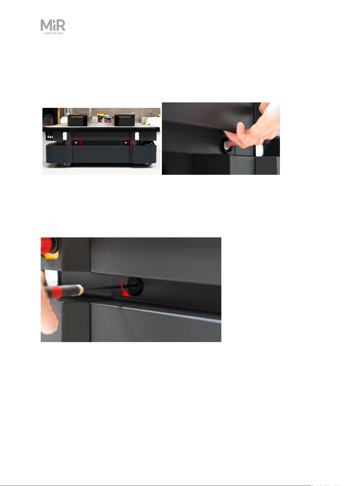
4.3 Side compartments
To open a side hatch, turn the two screws 90° with a flat-head screwdriver, and pull open the
hatch.
MiR1000User Guide (en) 12/2020 - v.1.4 ©Copyright 2019-2020: Mobile IndustrialRobots A/S. 29
4. Accessing the internal parts
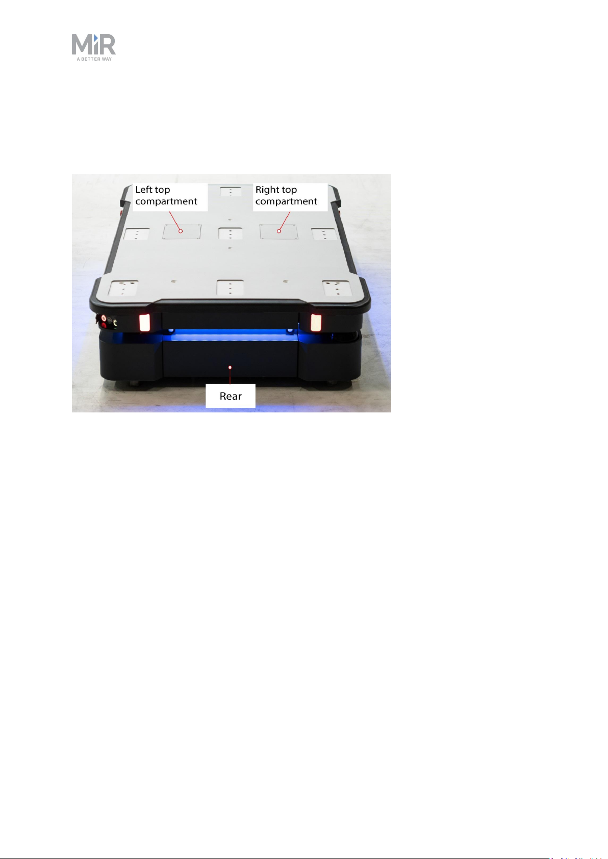
4.4 Top compartments
To open a top compartment, remove the four screws and lift off the top cover.
MiR1000User Guide (en) 12/2020 - v.1.4 ©Copyright 2019-2020: Mobile IndustrialRobots A/S. 30
 Loading...