

Page 1
INSTALLATION & OPERATION INSTRUCTIONS
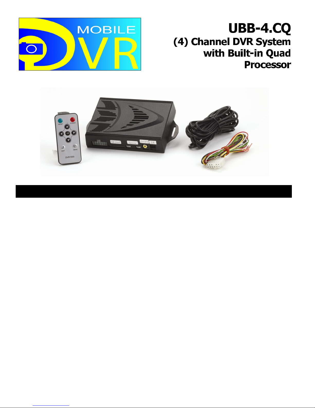
The ultimate in video recording technology, the UBB-4.CQ Mobile DVR system provides aroundthe-clock video surveillance recording for your vehicle. These recordings may be used in court
to show proof of any event that took place such as: accidents, theft, vandalism or car jacking. It
is a vehicle "black box" DVR system that can support up to four different cameras for
simultaneous recording around the vehicle. The system uses (3) separate trigger inputs
(Ignition, Security and Reverse) to initiate the recording of all four cameras and will store the
recordings onto (3) individual files on a removable SD card. The recordings can be reviewed onsite through an LCD monitor or the SD card can be removed and viewed on a computer.
FEATURES:
• Provides around-the-clock video surveillance recording for your vehicle
• Allows (4) different cameras to record simultaneously
• (3) Separate trigger zones: Ignition, dome light (security) and reverse light
• Recordings can be reviewed on-site through an LCD monitor or on your home computer
• Uses SD card (32GB max)
• Recordings are stored in (3) separate files on the SD card
• Resolution: 720 × 480
• Includes plug-in microphone for audio recording inside the vehicle
• Full functioning remote to access the system menus and features
• Plug-in IR sensor for remote
• Records time and date of the events
• System can be integrated with any alarm or remote start system
• Compatible with any SecurView camera or standard RCA camera
Page 2

2
TABLE OF CONTENTS:
Introduction 2
Pre-Installation Considerations 3
Cautions & Warnings 3
Hardware Included (What’s in the kit) 4
Wiring (12-Pin Harness) 5-6
Installing the DVR Module 7-8
Installing the Microphone 9
Installing the IR Sensor 10
Installing the LCD Monitor (Not Included) 10-11
Installing the SD Card 11
Installing the Cameras (Not Included) 12-14
Camera & Monitor Wiring 15
Installation Overview 16
Using the Remote & Battery Replacement 18
Screen Icons 19
Record & Playback Modes 20-21
The Menus 22
System Menu Structure 23
Video Menu Settings 24-26
Play Menu Settings 27-29
Setup Menu Settings 30-34
Screen Structure 35-37
Audio Recording & SD Card Management 37
Troubleshooting 38-39
Technical Specifications 39
INTRODUCTION:
This manual contains the information necessary for installing and operating your DVR system. If
any questions arise, contact your installation dealer or Crimestopper Security Products Inc.
This installation book is designed for the installer or individual with an existing understanding of
automotive electrical systems, along with the ability to test and connect wires for proper
operation. To ease installation, we suggest that you READ THIS MANUAL before beginning
your installation. This book is provided as a GENERAL GUIDELINE and the information
contained herein may differ from your vehicle.
DISCLAIMER:
Crimestopper Security Products, Inc. and its vendors shall not be liable for any accident
resulting from the use of this product. This system is designed to be professionally installed into
a vehicle in which all systems and associated components are in perfect working condition.
Page 3

3
PR PRE-INSTALLATION CONSIDERATIONS:
BEFORE BEGINNING, check all vehicle manufacturer cautions and warnings regarding
electrical service (AIR BAGS, ABS BRAKES, ENGINE / BODY COMPUTER AND BATTERY).
PLAN OUT YOUR INSTALLATION. You should pre-determine the location of the DVR Module
(Brain), Microphone, IR Sensor, Camera(s) and LCD monitor. This will save time and ease the
installation process. Please make sure that when you are determining the mounting location of
the DVR module that you take into account that you will need to retrieve the SD card at some
point. Be sure to mount this module in a location that will make it easy for you to do so.
USE VOLT/OHM METER to test and locate all connections. During this installation, you will be
testing for ignition power, dome light triggers, reverse lights, etc. Test Lights or Lighted Probes
could possibly damage a vehicle’s computer system or cause an airbag to deploy.
ADDITIONAL PARTS, such as additional relays, wire connectors and zip ties are not included
with this unit, and will be needed for your installation.
CAMERA(S) AND LCD MONITORS are not included with this kit and will need to be purchased
separately. Any SecurView™ cameras and monitors will be compatible with your UBB-4CQ
DVR system. However, you may also use any aftermarket camera and monitor that use a
standard RCA video connection. ALWAYS BENCH TEST all cameras and monitors before
actually installing them into the vehicle.
CAUTIONS & WARNINGS:
DAMAGE RESULTING FROM IMPROPER INSTALLATION IS NOT COVERED
UNDER WARRANTY!!!
DO NOT ROUTE ANY WIRING THAT MAY BECOME ENTANGLED with the brake/gas pedals,
steering column, or any other moving parts in the vehicle. If you are planning on installing the
DVR module under one of the seats, please make sure to leave slack on all wires and cables so
that when the seat is moved back and forward, the cables are not outstretched or broken. Also,
be sure to stay clear of any air bag or occupant sensors and connectors under the seats.
WHEN INSTALLING THE CAMERAS, BE SURE to double check behind the mounting
locations to make sure that you will not be drilling into any wire harnesses or other OEM
equipment. If you are installing the interior cameras on the headliner, be sure to double check
for clearance underneath the headliner so you will not drill through the outer roof or through any
wire harnesses, modules or air vents in the ceiling of the vehicle.
DO NOT route any video cables or harnesses in front of any curtain air bags or knee air bags in
the vehicle. Doing so may cause the air bags to fail in case of an accident causing injury to the
driver and passengers.
DO NOT install the LCD monitor in a location that will obstruct the driver’s view.
Page 4
4
INSTALLATION
•
•
HARDWARE INCLUDED: (What’s in the Kit)
NOTE: Cameras and monitor are sold separately from the system. Any SecurView™ camera
and monitor or any camera and monitor that use a standard RCA video output connection is
compatible with this DVR system. There are special packages are available which will bundle
the UBB-4.CQ system with up to four cameras.
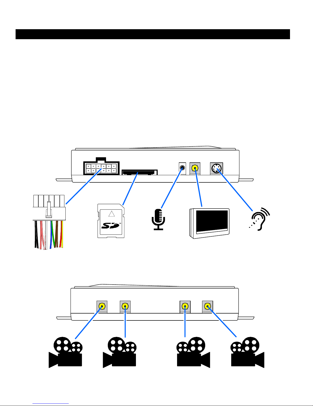
(1) Control Module
• (1) Full functional remote with battery
• (1) 12-pin power connector
• (1) 8GB SD card
FRONT VIEW
(1) IR sensor cable
• (1) Wired microphone
• (1) Instruction manual
• (1) Warranty card
MICROPHONE
SD CARD
POWER
BACK VIEW
Reverse Camera Front Camera
Dome (Inside)
Camera
LCD MONITOR
#2
IR SENSOR
VIDEO 1VIDEO 2VIDEO 3VIDEO 4
Front Camera
Page 5
5
INSTALLATION
WIRING: -12 Pin Connector-
Yellow: (+) 12V Battery Power
Connect this wire to a constant 12V power source such as the battery or any battery source
under the dash (Ignition barrel power harness or fuse box)
Red: (+) 12V Ignition Input
This input will activate the video inputs and begin recording when the ignition is turned on.
Connect this wire to an IGNITION circuit (or fuse in the fuse box) that shows +12 Volts when the
key is in both “On” and “Start” (WHEN CRANKING) positions.
Brown/White: (+) Dome Light Input
This input will activate the video inputs and begin recording when the door is opened. Connect
this wire to the positive dome light circuit in the vehicle. This circuit will show 12 volts when the
vehicle door is opened and rest at ground when the door is closed.
Brown: (-) Dome Light Input
This input will activate the video inputs and begin recording when the door is opened. Connect
this wire to the negative dome light circuit in the vehicle. This circuit will show ground when the
vehicle door is opened and rest open when the door is closed.
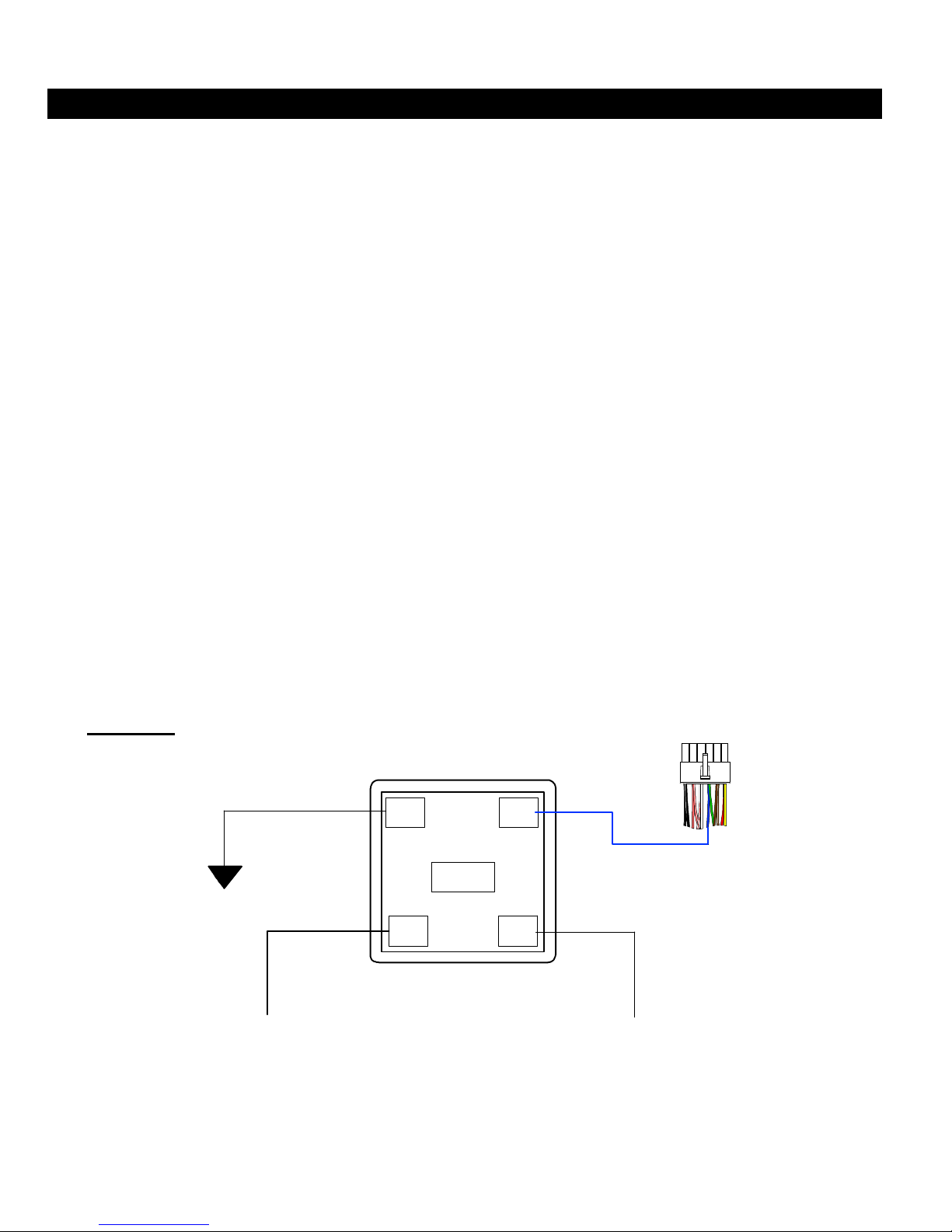
Blue: (+) Camera Power Output (200mA Max, REQUIRES RELAY)
This wire provides a 12V 200mA output to power up the camera(s) when any of the three trigger
inputs of the system are activated. Since this wire is only a 200mA max, a relay is required to
power the 1-3 cameras of the system. Connect blue wire to terminal #86 of relay. Connect
terminal #85 to chassis ground. Connect terminal #87 to a +12V constant battery source.
Connect Terminal #30 to the 1-3 camera power inputs. (See FIGURE 1)
FIGURE 1
Camera Power Relay
Blue 200mA Power Output
from UBB-4.CQ system
CHASSIS
GROUND
+12 VOLT BATTERY
White/Red: (+) 12V Reverse Light Input
This input will activate the VIDEO 4 input and begin recording when the vehicle is shifted into
reverse. Connect this wire to the 12V reverse light circuit in the vehicle. This circuit will show 12
volts only when the vehicle is shifted into reverse.
87A
RELAY
8685
3087
+12 Volt camera power
Page 6
6
INSTALLATION
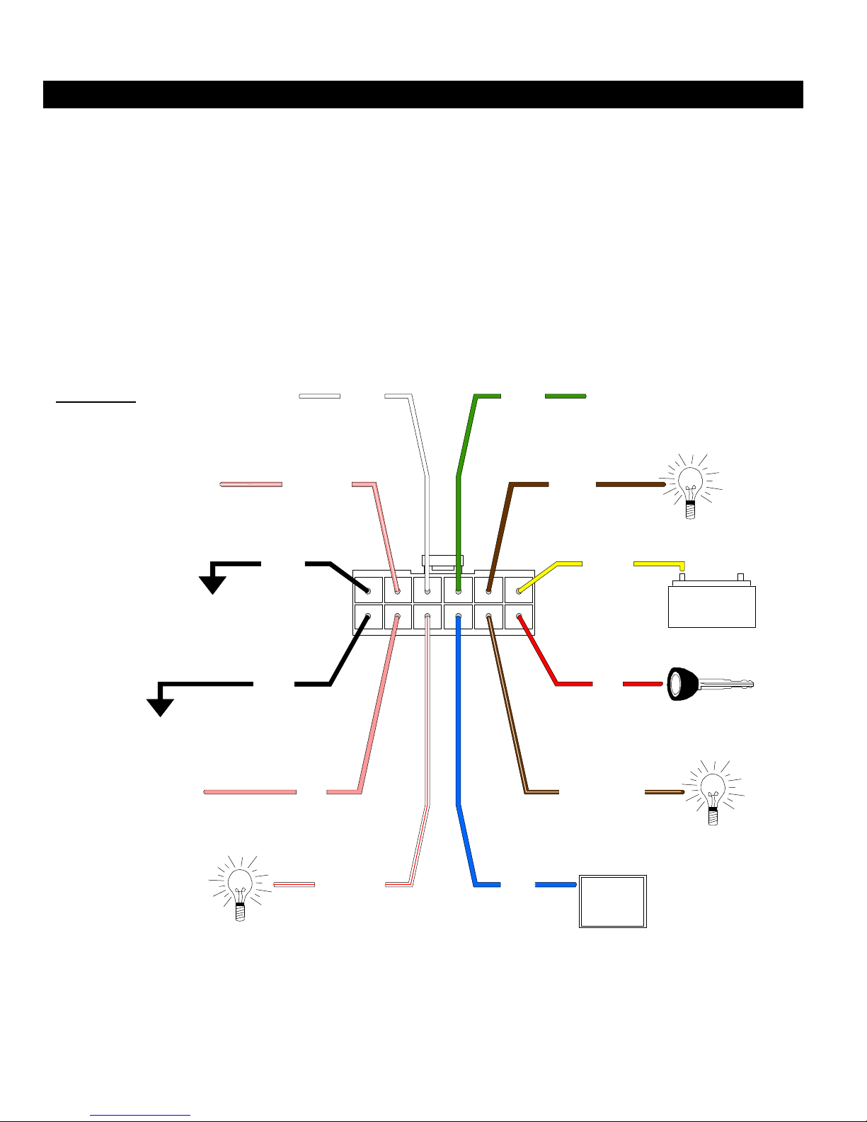
WIRING: -12 Pin Connector- (Continued)
Green: No Connection
White: No Connection
Pink: No Connection
Pink/White: No Connection
Black (2x): (-) Main System Ground
Connect these two wires to the CHASSIS METAL of the vehicle. Scrape away any paint or
debris from the connection point and use a star washer to ensure a good connection. Keep the
ground wire as short as possible.
FIGURE 2
12-Pin Harness
No Connection
WHITE
GREEN
No Connection
D
(-) Dome Light
+
+12 Volt Battery
+12 Volt Ignition
D
(+) Dome Light
-
Chassis Ground
No Connection
Chassis Ground
No Connection
PINK/WHITE
BLACK
BLACK
PINK
R
+12 Volt Reverse Light
WHITE/RED
BLUE
200mA max
BROWN
YELLOW
RED
BROWN/WHITE
+12 Volt Power output
for cameras
86 87
87a
85
30
(Please see relay diagram)
NOTE: Both the Brown and the Brown/White wires do not need to be hooked up at the same
time. You may use one or the other depending on the type of door circuit your vehicle has.
NOTE: Please make sure to use a relay on the Blue wire to power the cameras. Failure to do so
will result in damage to the system. (See FIGURE 1 on previous page)
Page 7
7
INSTALLATION
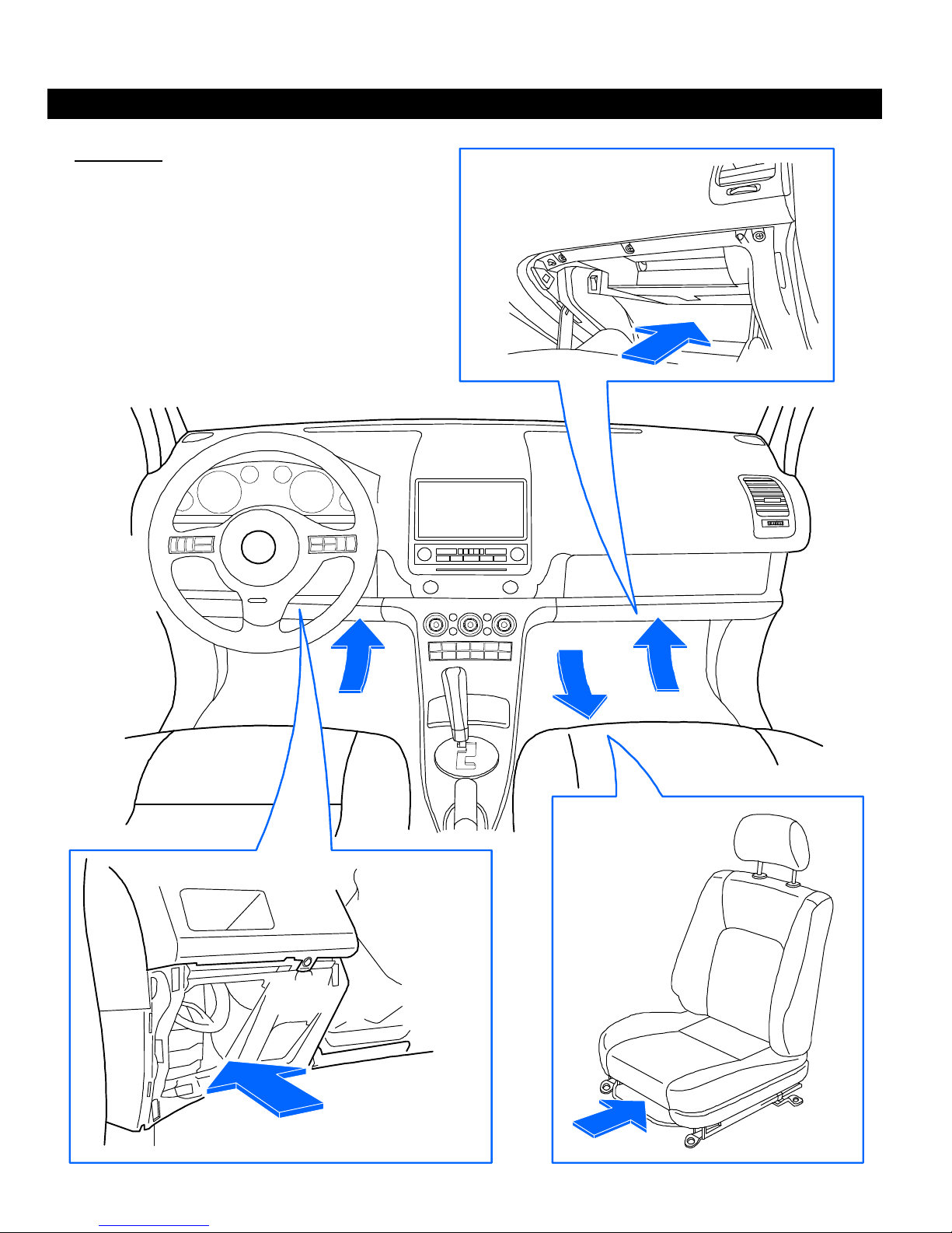
INSTALLING THE MODULE:
FIGURE 3
Make sure to install the DVR module in an
easily accessible location so that you can
retrieve the SD card easily
Also make sure that all video cables and
wires will not be pinched or caught on
any moving parts in the mounting location
Mount behind
the glove
box
Mount under the
passenger
seat
Mount under the
driver's side of
the dashboard
Page 8
8
INSTALLATION
INSTALLING THE MODULE: (Continued)
1. Carefully choose a location to mount the UBB-4.CQ main module. Keep in mind that you will
not only have many different cables and harnesses connecting to this module but you will
also need to be able to retrieve the SD card easily to view the recordings or change out the
SD card.
2. There are many different locations to mount the module. The primary choice is of course
under the dash board but you can also mount the module under the passenger seat or even
behind the glove box. (SEE FIGURE 3)
NOTE: If you are installing the module under the dash board or behind the glove box, make
sure to keep all cables clear of moving parts such as the steering column, pedals or vents. If
installing under the passenger seat, please make sure to leave slack on all cables to account
for the seat moving back and forward. Also make sure to stay clear of any air bag and
occupant sensors under the seat.
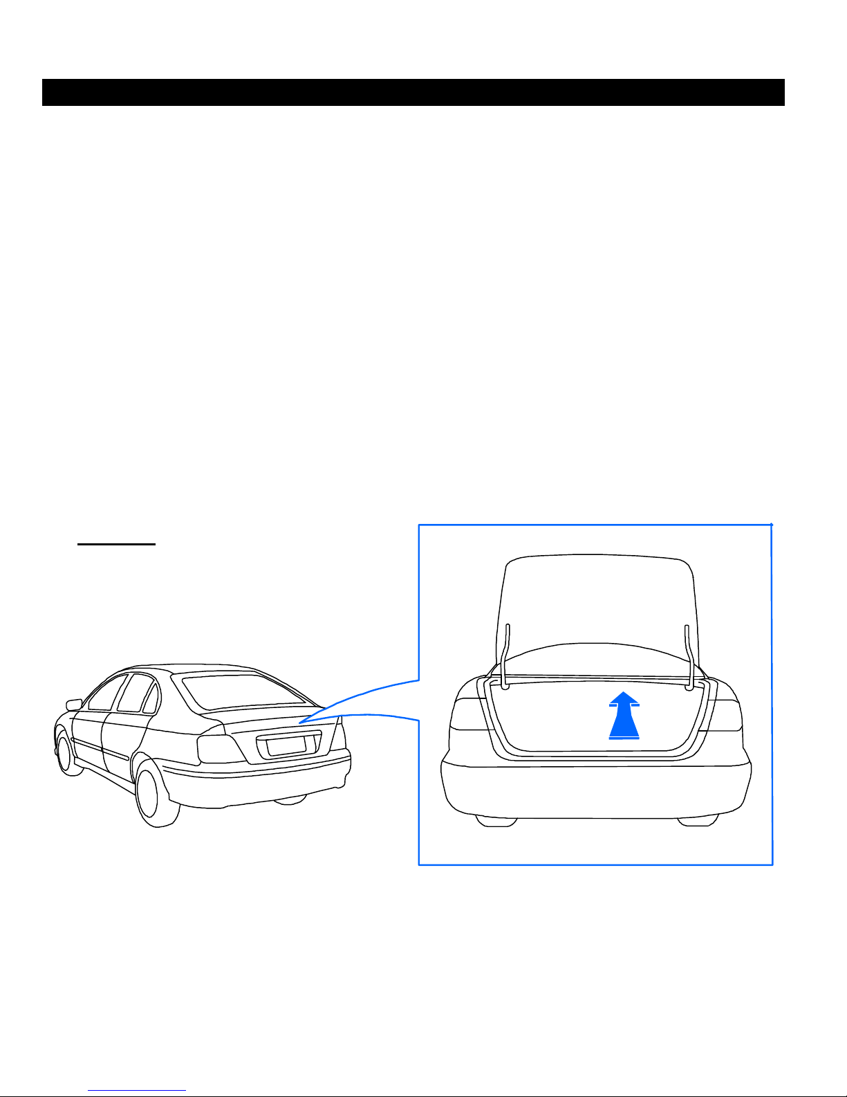
3. If installing on a car, you can sometimes mount the module underneath the rear deck inside
the trunk if there is not enough space anywhere else in the car. (See FIGURE 4) If you are
installing in the trunk, please make sure that the microphone and IR Sensor cables have
adequate length to reach up to the front of the vehicle.
FIGURE 4
Mount under the rear
deck inside the trunk
NOTE: On some older model cars, this mounting location will not be applicable because the
trunk lid tension rods go across the bottom of the deck and will not leave enough space to
mount. Some vehicles may also have other OEM equipment installed in this space such as a
navigation system, subwoofer or factory amplifier.
Again, please make sure to mount the module in a location where you can easily retrieve the SD
card from the system.
Page 9
9
INSTALLATION
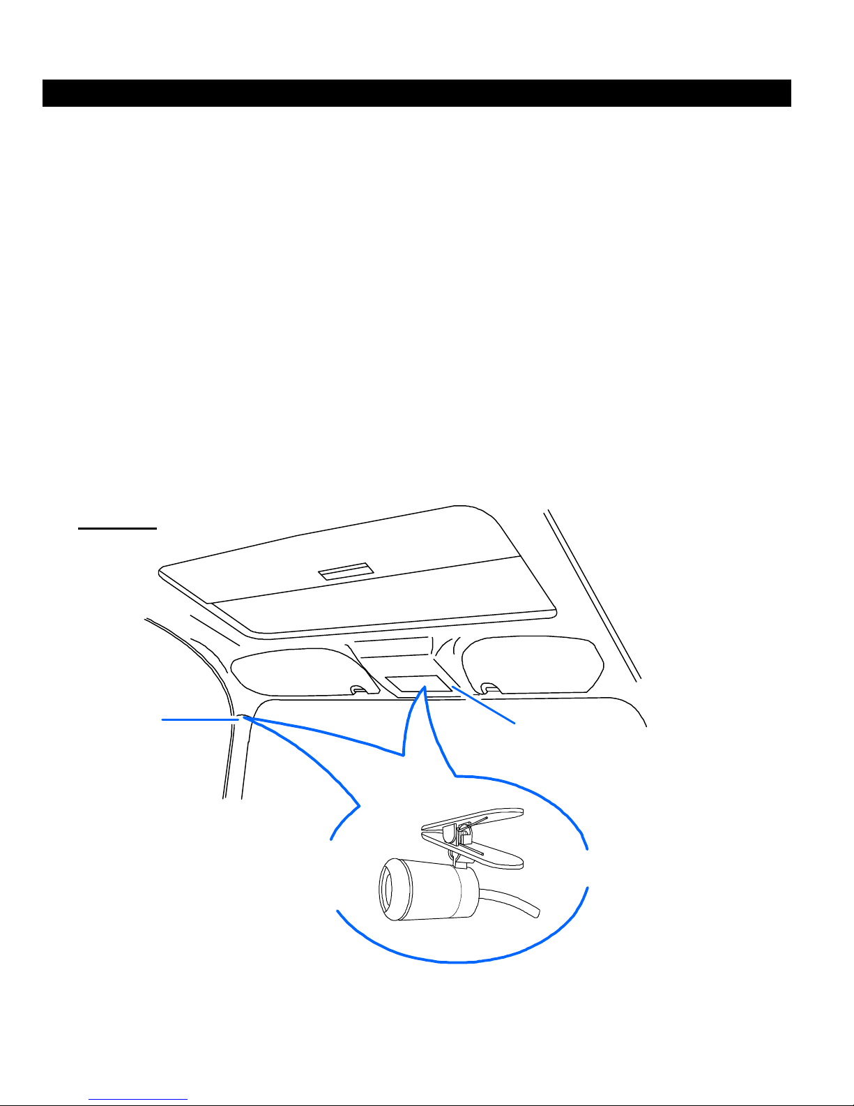
INSTALLING THE MICROPHONE:
1. The UBB-4.CQ system comes included with a small wired microphone that plugs into the
unit and can be mounted inside the vehicle for audio recording when the unit is activated.
2. You’ll want to install the microphone in a location where it will pick up any noises all around
the interior of the vehicle. It does not need to necessarily be mounted in the center of the
headliner but the higher up, the better. The best locations are the driver’s side A-Pillar or
custom mounted into the center roof console. (See FIGURE 5) In these locations, the
microphone should be able to pick up any noises inside the vehicle when the system is
recording.
3. The microphone comes with a small clip that you can use to loosely surface mount it to a
panel or a wire harness. If you are going to use this method, the best place to mount it would
be either on the top of the A-Pillar. If you have a rear view mirror that has map lights or any
electronic functions, then you can most likely clip the microphone to the mirror’s wire harness
coming from the headliner.
NOTE: You can remove the clip by sliding it sideways off of the microphone. This will allow
you to custom mount the microphone into a panel if you choose to do so.
FIGURE 5
A-Pillar
A-pillar or custom mount it
Clip microphone onto
to the headliner console
Headliner
Console
NOTE: Clip can be removed
for custom mounting
NOTE: Try to avoid mounting the microphone next to any speakers or Bluetooth™ devices in
the vehicle. This may cause the microphone to pick up feedback and will not give you proper
audio recording.
Page 10
10
INSTALLATION
INSTALLING THE IR SENSOR:
1. The UBB-4.CQ includes a small wired IR sensor has plugs into the module and is mounted
in a location where the system’s remote control can transmit line-of-sight to it. This sensor is
responsible for allowing the remote control to communicate with the module and allow you to
navigate through the systems menus and settings. It is very important to place this sensor in
a location that is out of the way but can easily be seen by the remotes Intra red eye.
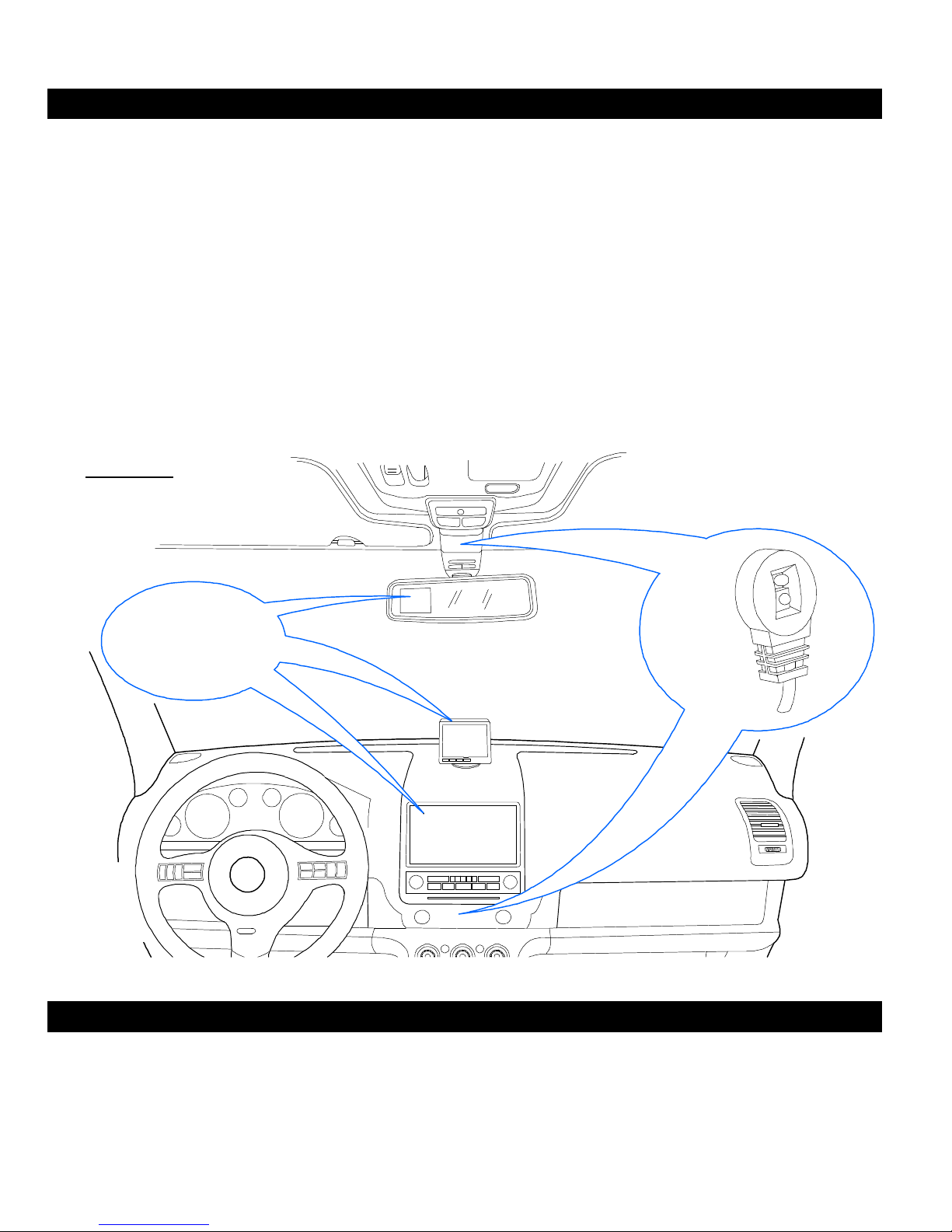
2. Mount the IR sensor either on the dash board or up by the rear view mirror so that you can
easily point the remote at it to operate the system and access the menus and settings. (See
FIGURE 6) The sensor has double-side tape to mount it to the surface.
NOTE: If you do not install the IR sensor, the remote will not communicate with the module
and you will not be able to access the system’s menus or change any settings of the DVR
system. The IR Sensor also has a green LED to indicate whether the system is on or off.
FIGURE 6
Mirror Mount,
Universal or
In-Dash monitor for
video playback
IR Sensor
INSTALLING THE LCD MONITOR:
1. The UBB-4.CQ uses a standard RCA video output for connection to a monitor for on-sight
playback of the recordings and to view the system menus. Any SecurView™ monitor or any
aftermarket universal, rear view mirror or in-dash style monitors that use a standard RCA
video input will be compatible with this DVR system. (See FIGURE 6)
Page 11
11
INSTALLATION
INSTALLING THE LCD MONITOR: (Continued)
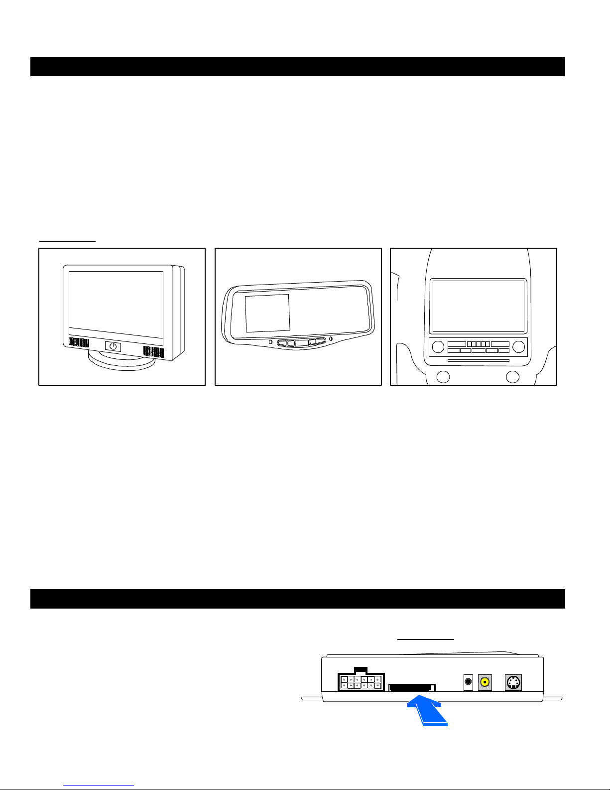
2. There are several different types of monitors that can be used with this system. You can use
any rear view mirror, universal or in-dash style monitors as long as they have a standard
RCA video input (See FIGURE 7)
3. You will need to refer to the installation instructions of the monitor to find out how to install
them in the vehicle but most of the monitors are very simple to install and will require minimal
installation time. Most monitors will have at least one video input to connect to the UBB-
4.CQ system and will require you to connect power to a +12V ignition source so that the
monitor will come on when the key is on at all times.
FIGURE 7
UNIVERSAL REAR VIEW MIRROR IN-DASH
NOTE: The LCD monitor is NOT INCLUDED with the UBB-4.CQ system and will have to be
purchased separately. If you are going to use the UBB-4.CQ system with an OEM in-dash
monitor than some special interface parts will be required to integrate the OEM equipment with
the aftermarket RCA video plugs.
If you do not install a monitor with the UBB-4.CQ system, then you will not be able to access the
system menus and change any of the settings. You will also not be able to view the recordings
onsite and you will have to remove the SD card and connect it into a PC or Apple computer to
view the recordings. It is strongly recommended that you install and connect an LCD monitor
with this DVR system.
INSTALLING THE SD CARD:
The SD card is housed in a small opening
on the front side of the main module next to
the 12-pin power harness. (See FIGURE 8)
Insert the SD card into the housing and
press down to lock it into place. To retrieve
the SD card, press down on the top side of
it and it will spring release out of the
housing.
FIGURE 8
SD CARD HOUSING
Page 12
12
INSTALLATION
INSTALLING THE CAMERAS:
1. The UBB-4.CQ has four camera inputs and can simultaneously record from all for cameras
when the system is activated. The system’s four inputs are for a Front camera (VIDEO 1),
Reverse Camera (Video 4), Security or Dome Light Camera (Video 3) and also a Video 2
input for a 4th general purpose camera. The system will automatically detect when a camera
is plugged into the specified input and will start simultaneously recording on all cameras
when the system is activated either by the Ignition, Reverse or Security (Dome Light)
triggers.
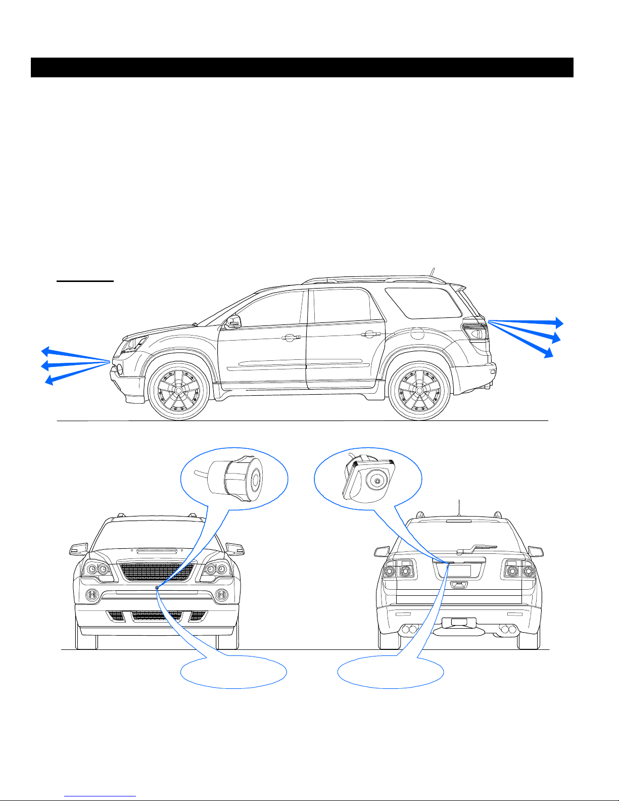
2. The forward and reverse cameras will mount on the front and the rear of the vehicle like
normal camera installations. You can use any SecurView™ camera or any aftermarket style
camera that uses a standard RCA video output. (See FIGURE 9)
FIGURE 9
Reverse Camera
VIDEO 4
Forward Camera
VIDEO 1
Flush Mount Camera
(Not Included)
Forward Camera
VIDEO 1
Reverse Camera
VIDEO 4
Embedded Mount Camera
(Not Included)
NOTE: Using a camera that has Normal or Reverse image selection is usually the best way to
go. This way, if you have to install the cameras in different locations, you can flip the image to
make sure that you are viewing it correctly on your monitor and in your recordings.
Page 13
13
INSTALLATION
INSTALLING THE CAMERAS: (Continued)
3. The forward camera RCA connects to the VIDEO 1 port on the UBB-4.CQ and the Reverse
camera RCA plugs connects to the VIDEO 4 port on the UBB-4.CQ.
4. For the interior camera, you will most likely want to use a camera that is smaller and less
noticeable. The SecurView™ SV-007, SV-6828 or SV-6922.LM.II cameras are perfect
solutions since they are all small but high-resolution cameras. However, any camera with an
RCA video output connection will work just fine.
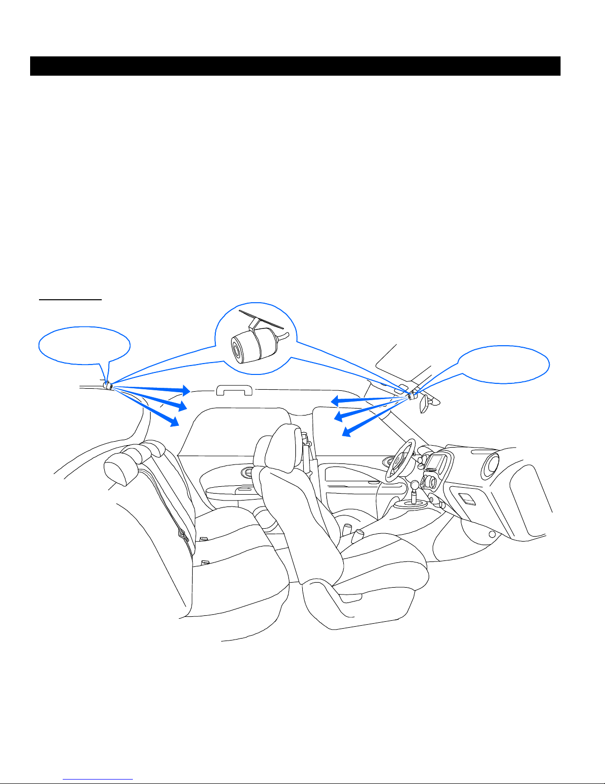
5. Mounting the interior camera higher up on the headliner is usually the best place. The
interior camera connects into the VIDEO 3 port on the UBB-4.CQ system. The VIDEO 2 port
can be used as an extra video source for another front camera, so you can place the camera
wherever you want on the interior or exterior of the vehicle. In this case, we show it being
used on the interior of the vehicle. (See FIGURE 10)
FIGURE 10
Lip Mount Camera
(Not Included)
Interior Camera
VIDEO 3
Front #2 Camera
VIDEO 2
NOTE: When installing the interior camera(s), try to mount them in a location where the entire
interior of the can be viewed by the camera. Usually the best place for this is up higher on the
headliner either in the front or the rear of the interior. If you are using both the VIDEO 2 and
VIDEO 3 cameras for the interior, then you should be able to view all angles of the vehicle
interior (See FIGURE 10)
Page 14
14
INSTALLATION
INSTALLING THE CAMERAS: (Continued)
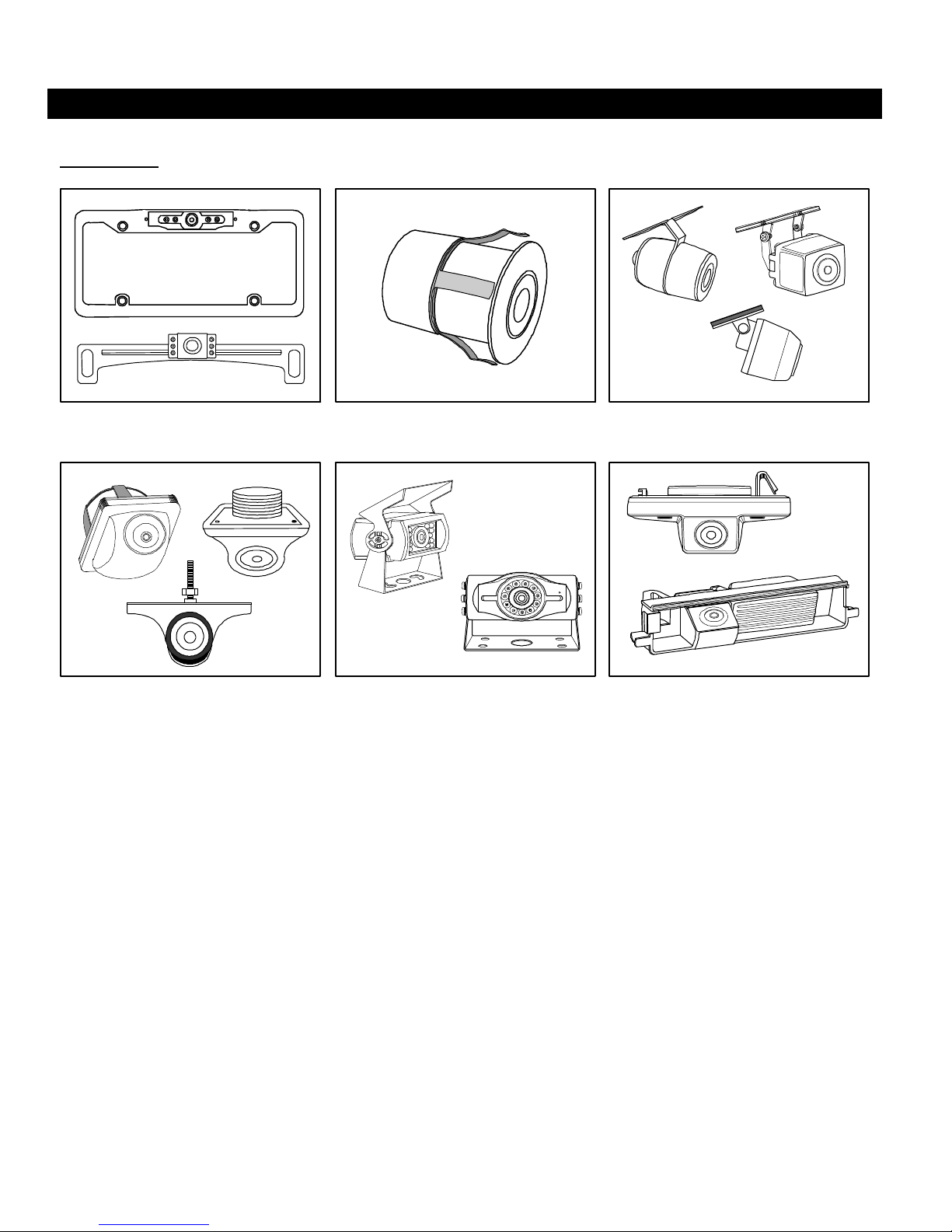
FIGURE 11
LICENSE PLATE MOUNT FLUSH MOUNT LIP MOUNT
EMBEDDED MOUNT HANGING STYLE CUSTOM OEM STYLE
NOTE: There are several different types of SecurView™ cameras available that are compatible
with this DVR system. (See FIGURE 11) However any standard RCA type video output camera
will be compatible. Please refer to the instructions included with the cameras for specifics on
how to mount them to the vehicle.
Most SecurView™ cameras will come with a normal/reverse image selection which will allow
you to flip the image from right to left depending on where the camera is to be mounted on the
vehicle. This is very useful for using the same style of camera to mount on the front, back, left
and right side of the vehicle.
Select model SecurView™ cameras will also have a programmable parking line feature. This is
very useful when using a camera in the front or rear of the vehicle. The parking lines are
distance guides programmed into the camera sensor that will display when the camera is on
and help the driver accurately judge the distance on the front of rear of the vehicle depending on
where the camera is mounted.
Cameras are NOT INCLUDED with the UBB-4.CQ system and will have to be purchased
separately.
Page 15
15
INSTALLATION
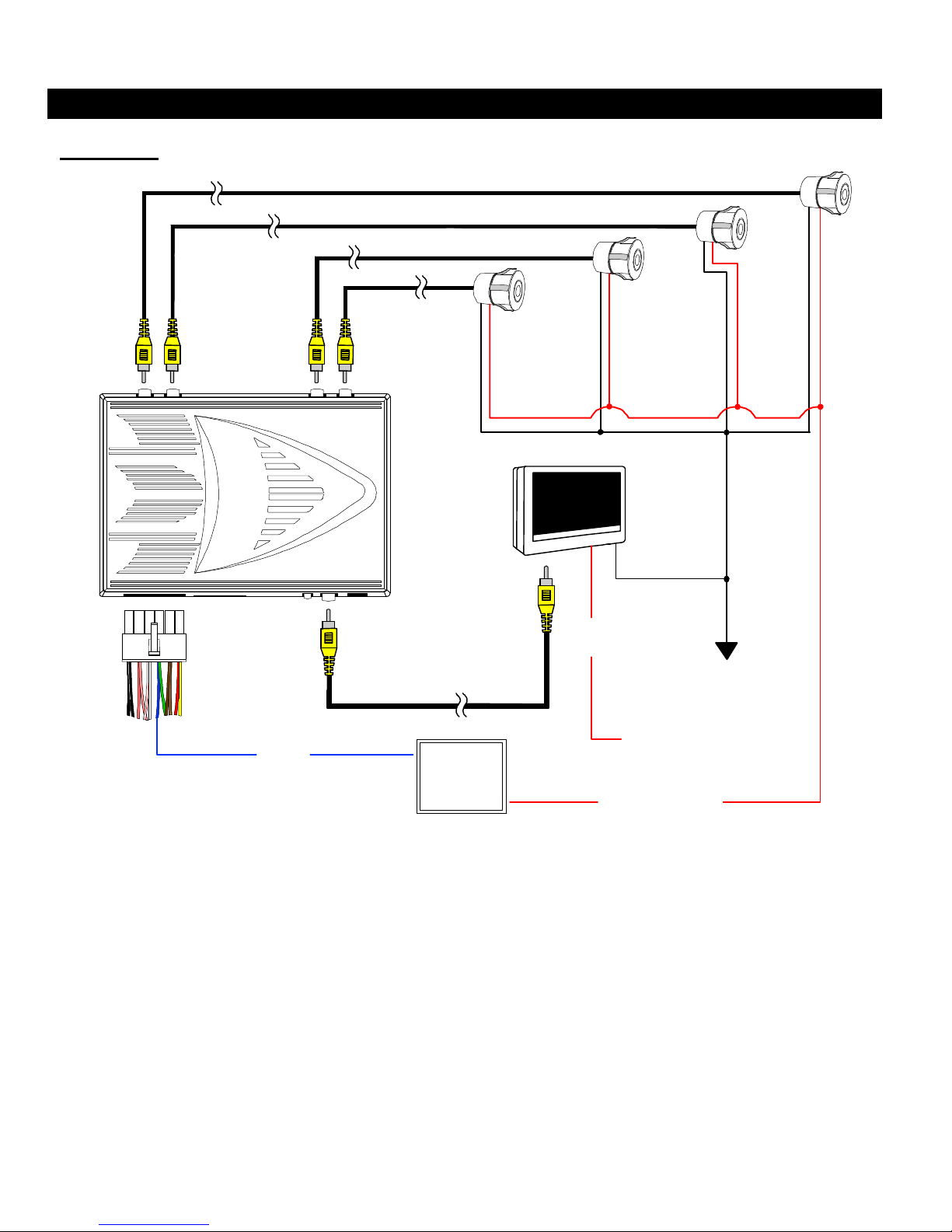
CAMERA & MONITOR WIRING:
FIGURE 12
Video
1
Video
2
Video
3
Video
4
Reverse
Front (Ignition)
Dome
(Security)
LCD
Monitor
Chassis
Ground
+12V Ignition
Camera Power
12-Pin
Power Plug
BLUE
(Please see relay diagram)
(Page 5)
Main
Module
86 87
85
Monitor
Video
Monitor
Power
87a
30
1. Connect power wires from all 4 cameras to the Blue 200mA power output wire from 12 pin
power connector of the UBB-4.CQ system using a relay. (See FIGURE 12) This way when
the system is powered on either by the Ignition (Red) wire or the Dome Light (Brown or
Brown/White) wires of the system, all 4 cameras will activate and begin recording.
NOTE: Please make sure to see the specific wiring instruction for the camera power relay on
page 5 of this manual. Failure to install the relay will cause damage to the DVR system
2. Connect the power wire from the LCD monitor to a +12V ignition source. This way when the
ignition is turned on the monitor will power up and start viewing the camera(s) when the DVR
system is activated. (See FIGURE 12)
3. Connect all ground wires of the camera(s) and monitor to ground. (See FIGURE 12)
Page 16
16
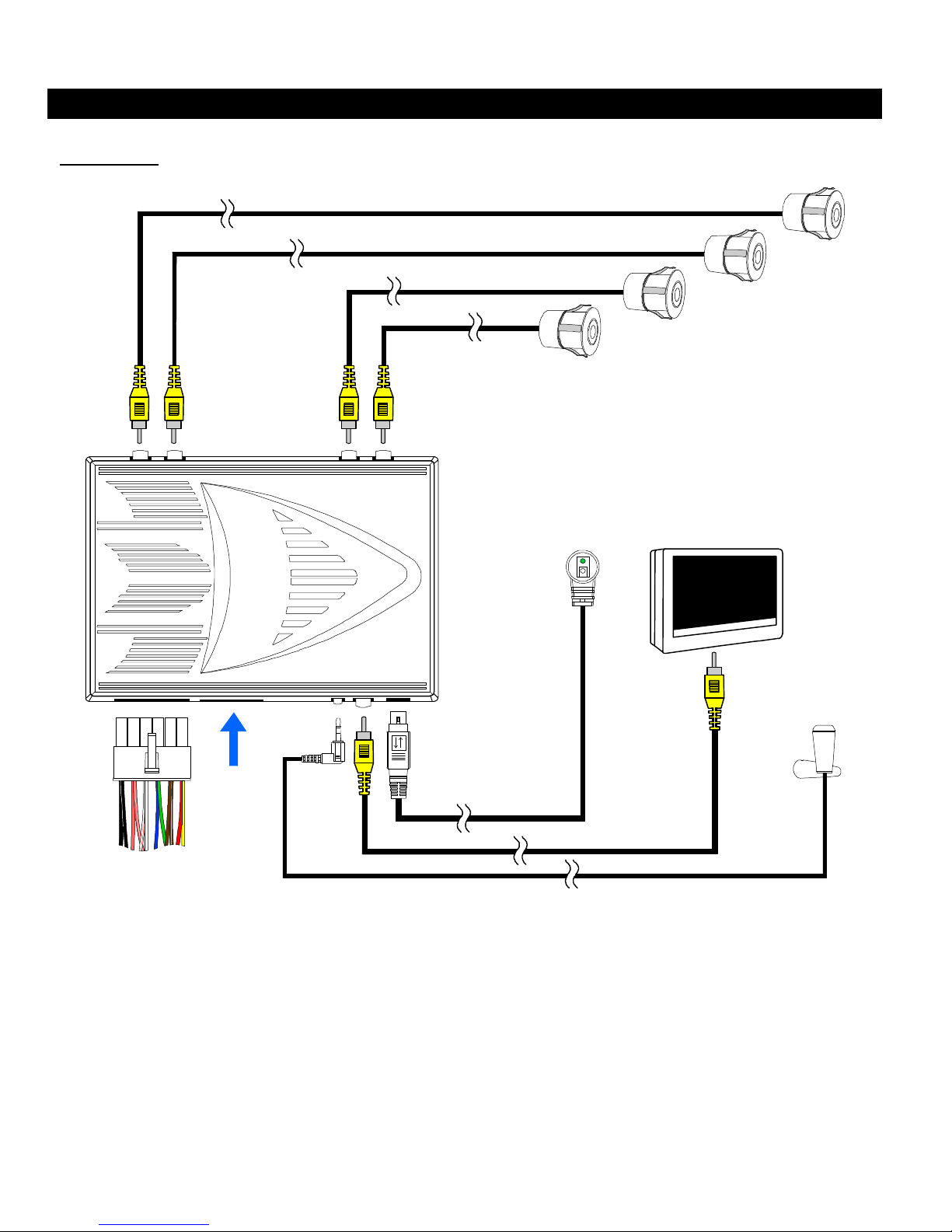
SYSTEM OVERVIEW:
FIGURE 13
Video
1
Video
2
Video
3
INSTALLATION
Front
Camera
Video 2
Camera
Dome (Inside)
Camera
Reverse
Camera
Video
4
IR Sensor
Main
Module
SD Card
Power Plug
(See Power Plug wiring diagram)
(PAGE 6)
LCD Monitor
Microphone
FIGURE 13 is a general overview of how all of the hardware plugs into the system once the
installation is complete. All hardware is included accept for the camera(s) and LCD monitor
which is sold separately. The system will automatically detect how many cameras are plugged
into the system and will display them accordingly on the monitor.
This DVR system can also be integrated with any aftermarket security system for extra
protection. This way if the shock sensor of the security system goes off, the unit will activate and
start recording. The system will also begin recording if an on-board remote start system is
activated and the ignition turns on.
Page 17
17
UBB-4.CQ
OPERATING INSTRUCTIONS
CONGRATULATIONS on your choice of a Mobile DVR™ Vehicle Black Box quad DVR
system by Crimestopper Security Products Inc. This section of the manual contains the
information necessary for operating your UBB-4.CQ system. If any questions arise, contact
your installation dealer or Crimestopper Security Products Inc.
CRIMESTOPPER SECURITY PRODUCTS, INC.
1770 S. TAPO STREET, SIMI VALLEY, CA. 93063
PHONE: 800-998-6880
FAX: 805-581-9500
www.crimestopper.com
Page 18
18
OPERATION
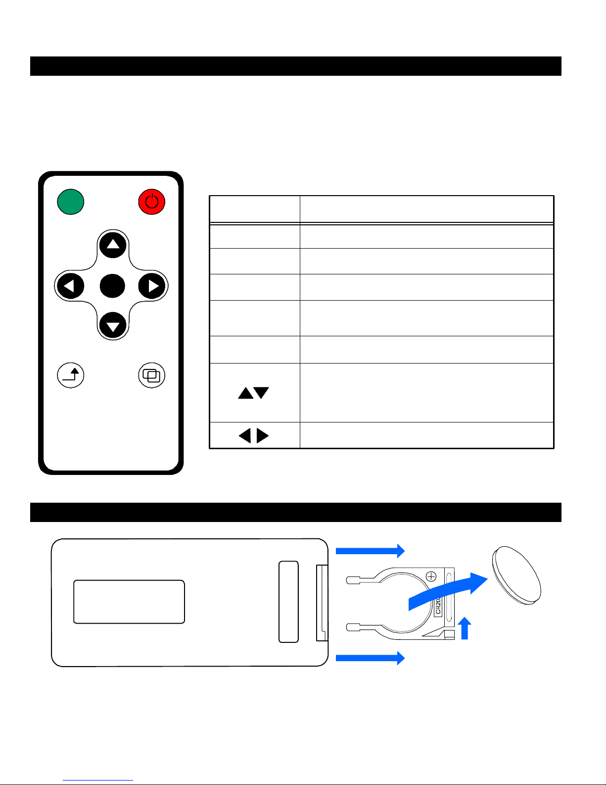
USING THE REMOTE:
The UBB-4.CQ system can be setup by using the hand-held remote control and IR sensor that
is included with the system. The remote will communicate with the system through the IR
sensor. You can navigate through all of the system menus and change any of the settings using
the different buttons on the remote. The remote will also allow you to easily switch the system
back and forth between Recording Mode and Playback Mode.
REC/PB POWER
OK
EXIT MENU
VEHICLE DVR
BUTTON FUNCTION DESCRIPTION
POWER
MENU
EXIT
OK
REC/PB
Toggle system power On/Off
Press to enter system settings menu
Press to exit system settings menu
In setup menu, press to confirm option selection
and enter option sub-selection menu
Switches between record and playback mode
In setup menu, controls up/down select operation
In normal operation, controls zoom-in/zoom-out
of selected video input
In setup menu, controls left/right select operation
REPLACING THE REMOTE BATTERY:
Lock Tab
Slide the lock tab sideways and then pull outward to remove the battery tray. The remote uses a
CR2025 battery to operate. Insert the battery back into place. There is a + symbol on the tray to
indicate that the positive side of the battery faces that direction. Push the battery tray back into
the remote until you here it click and lock into place.
Page 19
19
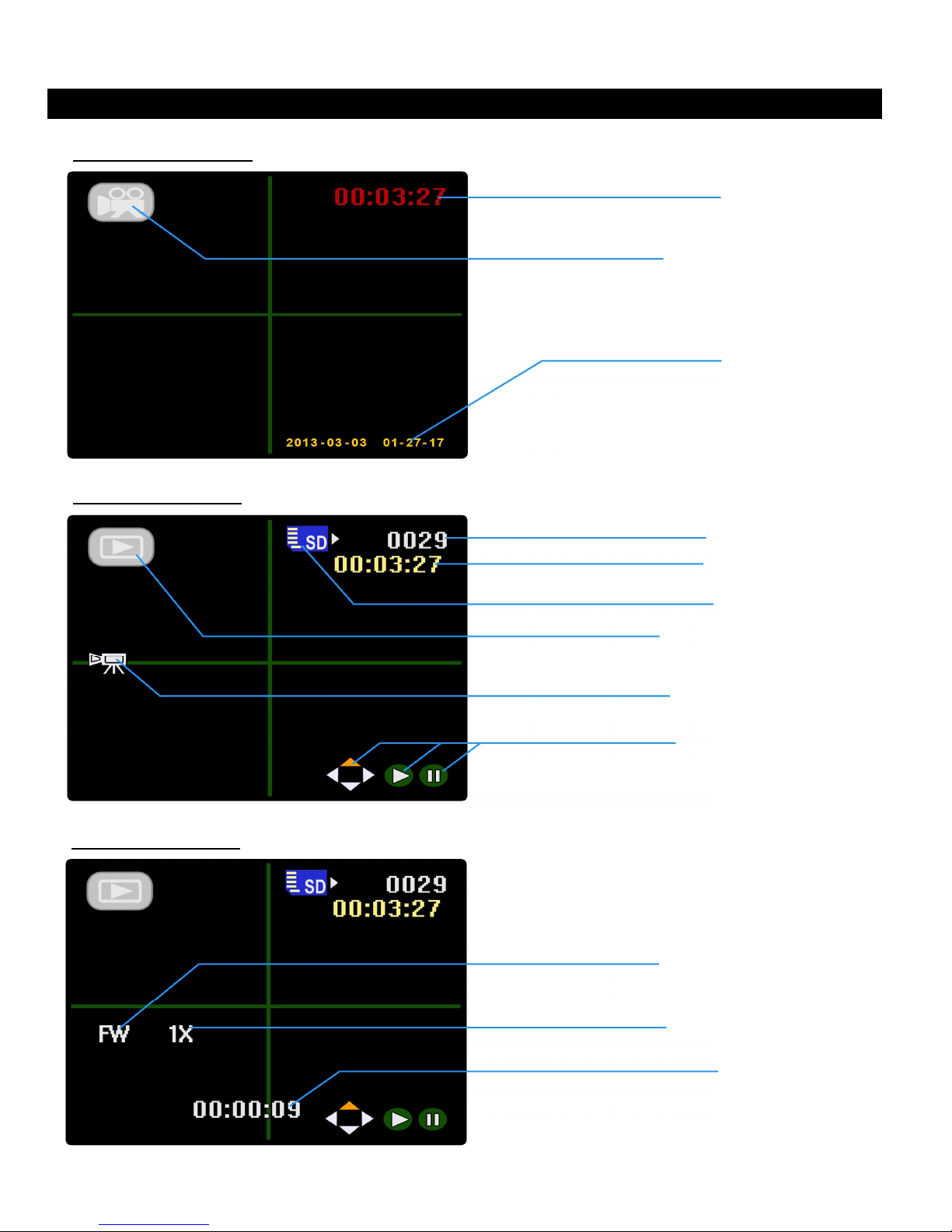
SCREEN ICONS:
RECORDING MODE
PLAYBACK MODE
OPERATION
Recording Time
Record Mode icon
Time & Date
Stamp
PLAYBACK MODE
Playback Mode icon
Video File Number
File Record Time
SD Card Read icon
Preview Mode icon
Playback Control
Video Playback Direction
Video Playback Speed
Video File Playback
Elapsed Time
Page 20
20
OPERATION
RECORD & PLAYBACK MODES:
The UBB-4.CQ system will automatically begin recording when the ignition is turned on or the
door is opened. If the ignition is on, the LCD monitor will activate and display the “Recording
Mode” screen. You can stop the Recording Mode and enter “Playback Mode” at anytime by
pressing the green REC/PB button on the remote. If you wish to exit Playback Mode and
resume recording, press the REC/PB button again on the remote.
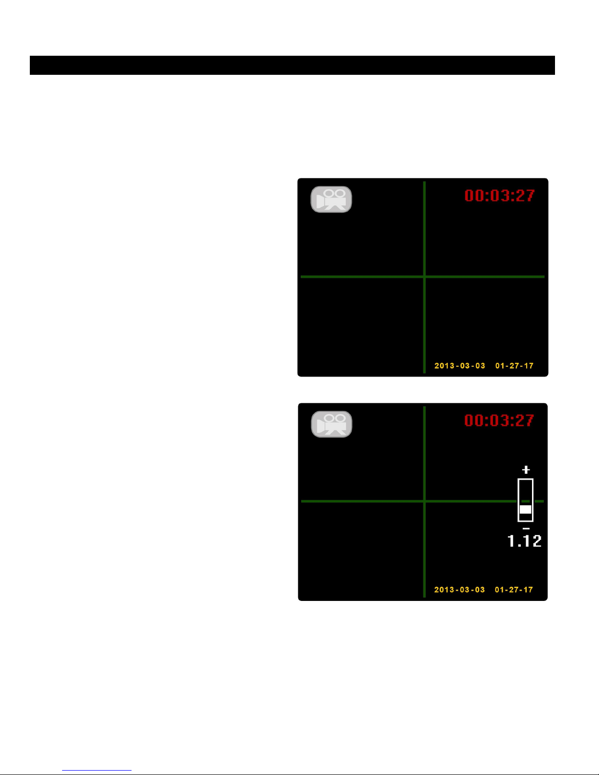
RECORDING MODE:
When the system is activated, it will
automatically enter Recording Mode and
display all cameras on the LCD monitor. A
camera icon will appear in the upper left
corner of the screen to tell you the system is
recording. The recording interval time will
also be displayed in red in the upper right
corner of the screen as it counts up. The
Time and Date will be displayed in the lower
right corner of the screen and will be saved
on each recorded file. Recording mode will
continue until the system is powered down
(Ignition off or door closed) or by pressing
the green REC/PB button on the remote.
In Recording Mode, you can zoom in and out
on the recordings by pressing the ▲▼
buttons on the remote. A small distance
meter will appear on the right side of the
screen and the image will begin to zoom in
and out. The zooming effect will also be
saved to the recording and stored on the SD
card so when you are reviewing the
recordings, you will be able to see the
zooming effect.
NOTE: The zooming effect will be reset once
the system is powered down (Ignition off or
door circuit opened and closed)
When Recording Mode is activated, the system will
automatically detect how many cameras are plugged in and display them accordingly on the
LCD monitor. (Please see the SCREEN STRUCTURE section of this manual on page 42). All
cameras will be activated by the ignition circuit or the door trigger circuit. The reverse camera
(VIDEO 4) circuit is the only camera that will display by itself when the vehicle is shifted into
reverse. Once the vehicle is shifted back into drive, the rest of the cameras will be displayed
again on the LCD monitor. All recordings are stored on the system’s SD card with the Time and
Date stamp and can be viewed at anytime by pressing the REC/PB button on the remote.
RECORD MODE SCREEN
ZOOMING FEATURE
Page 21
21
OPERATION
Press the green
REC/PB
button on the remote to enter
RECORD & PLAYBACK MODES: (Continued)
PLAYBACK MODE:
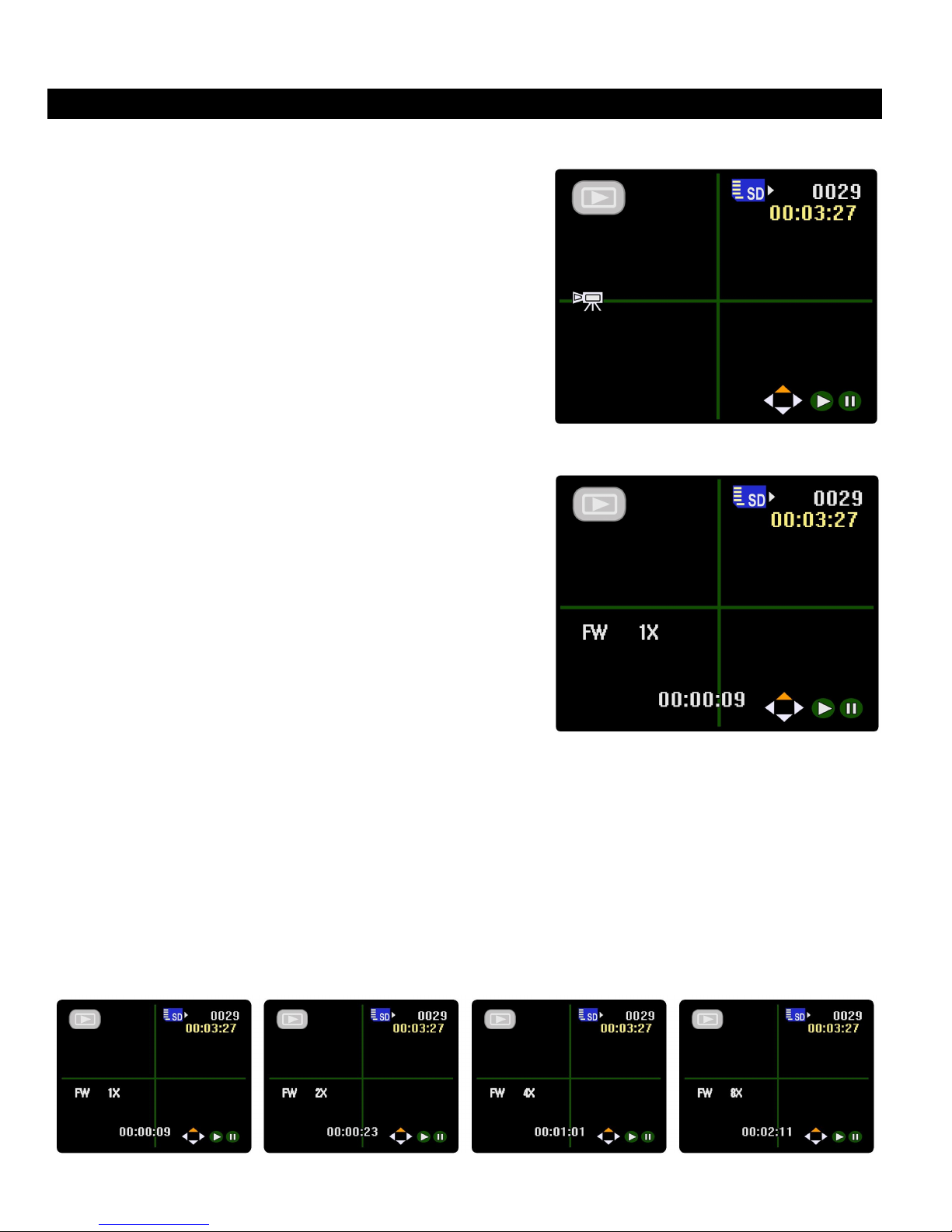
Playback Mode. Once on this screen, you will see
other icons appear. The first icon you will notice is the
Playback icon appears in the upper left corner where
the camera icon used to be. This is to let you know that
you are in Playback Mode. You will also see a File
Number and File Recording Time appear in the upper
right corner. This represents the latest recording the
system has just completed. At this point you can either
stay on this recording of you can cycle through the
previous recordings by using the ◄► buttons on the
remote and you will notice the File Number and File
Recording Time will change as you cycle through
them. (Screen 1)
A set of Playback Controls will appear at the bottom
right corner of the screen showing PLAY and PAUSE.
If you press the ▲ button on the remote, the recording
will begin playback. Pressing the ▲ button again will
pause the recording. The blue SD Card icon in the
upper right corner is to let you know that the SD card is
being accessed by Playback Mode and that it is
working properly. The Preview Mode Icon will only
appear when cycling through the recordings. This is to
let you know that you are “Previewing” the recordings
and not actually playing them yet. (Screen 1)
When the recordings are being viewed in Playback mode (Screen 2), you will notice that a small
counting-timer icon appears in the lower center of the screen. This displays the elapsed time of
the recorded file as it is played back. You will also notice that a Video Playback Speed and
Direction icon appear where the Preview Mode icon used to be. These are useful in case you
have a large file and you want to fast forward or rewind to a specific part of the recording.
Pressing the ◄► buttons on the remote will allow you to fast forward or rewind the recording
and you will notice the direction icon will change between FW (Forward) or BW (Backward) and
the speed icon will change between 1X, 2X, 4X and 8X depending on how fast you want to skip
through the recording. (See Below)
PLAYBACK SCREEN (1)
PLAYBACK SCREEN (2)
Page 22
22
OPERATION
OK
VIDEO
MENU
: PLAY
MENU
:
SETUP MENU
:
VIDEO
MENU
THE MENUS:
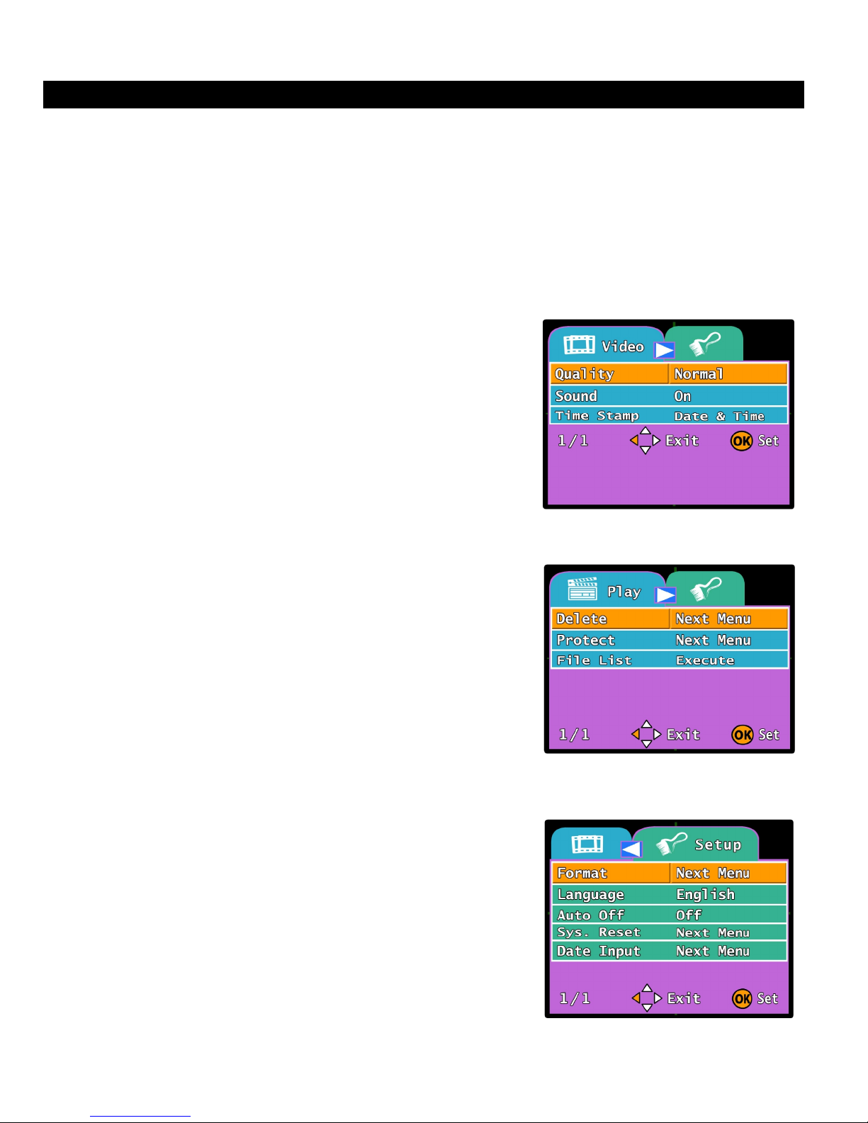
The UBB-4.CQ system has three separate menu pages; Video (Record), Play (Playback) and
Setup. All three menus have different features that can be accessed for different features and
settings of the system. The “Video” menu can only be accessed while in Recording Mode. The
“Play” menu can only be accessed while in Playback Mode and the “Setup” menu can be
accessed from either Record or Playback modes.
NOTE: All Recording and Playback function will automatically stop when any of the system’s
menus are accessed.
This menu will allow you to access recording features such
as: Video Quality, Audio Settings and Time & Date Stamp
adjustments.
• While in Recording Mode, press the MENU button on
the remote to pull up the Video Menu
• Use the ▲▼ buttons to navigate through the menu
options
• Press the OK button to access the selected option
This menu will allow you to delete or save specified video
files as well as access a full library of all recordings.
• Press the REC/PB button on the remote to enter
Playback Mode.
• Press he MENU button to pull up the Play Menu
• Use the ▲▼ buttons to navigate through the menu
options
• Press the
This is the main menu of the system and will allow you to
access all of the system settings such as: SD Card Format,
Language settings, Time & Date settings, etc.
.
• Press the MENU button on the remote in either
Recording Mode or Playback Mode.
• Press the ► button to pull up the Setup Menu.
• Use the ▲▼ buttons to navigate through the menu
button to access the selected option
options
• Press the OK button to access the selected option
Page 23
23
OPERATION
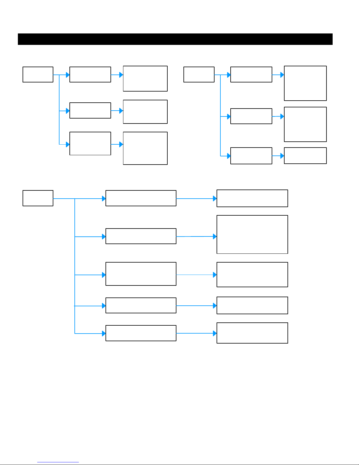
SYSTEM MENU STRUCTURE:
RECORD MENU PLAYBACK MENU
MENU
SETUP MENU
MENU
Quality
Audio
Time Stamp
High
Normal
On
Off
Off
Date Only
Time & Date
Format
Language
MENU
Delete
Protect
File List
Cancel Execute
English Français
Deutsch Italiano
Español
Single
All
Select
Single
All
Select
Select File
Auto Off
Sys. Reset
Date Input Off Set
1 Min. 3 Min.
5 Min. Off
Cancel Execute
The diagram above shows the three menu structures for the UBB-4.CQ DVR system. When you
enter the setup menus using the hand-held remote, this is the order of all of the system settings
that you can expect to see. It has everything that you will need including time and date settings,
recording time settings, SD card formatting and even the playback options for your recordings.
WARNING: Although you can access the menus at any time as long as the ignition is on, please
be very cautious and DO NOT use the remote while driving. Please make sure that the vehicle is
stopped and in park before accessing the DVR menus. Failure to pay attention to the road while
driving may cause injury to other drivers and pedestrians.
Page 24
24
OPERATION
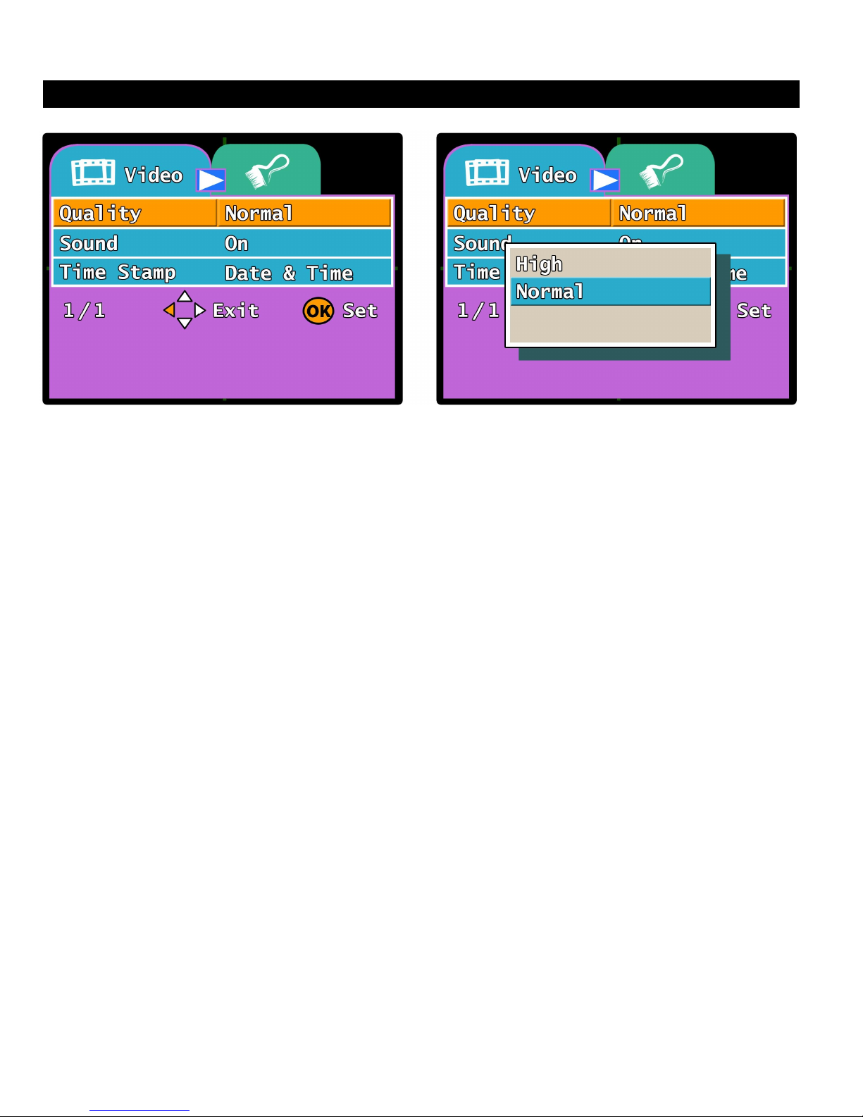
VIDEO MENU - Quality:
This option changes the video recording quality of the UBB-4.CQ system. If the HIGH option is
selected, the system will reduce the H.264 compression rate and make the video quality better
and much higher resolution. However, doing this will cause the recording time to reduce as well
making shorter video files. In the NORMAL option, the system can record around 6 minutes
each video file. With the HIGH option selected, the system will record around 4 minutes each
file. The default option is set to NORMAL
1. While in “Recording Mode”, Press the MENU button on the remote to enter the VIDEO
Menu.
2. The “Quality” option is the first option selected in the menu.
3. Press the OK button to enter the “Quality” feature setting. Use the ▲▼ buttons to select
either the NORMAL or HIGH option. Press the OK button to select the option you wish to
change to.
4. The system will automatically change the setting and return you to the VIDEO menu
NOTE: You may press the EXIT button at anytime on the remote to exit the menu settings if you
do not wish to change any of the options. Exiting the menu will not change any of the
settings on the system.
NOTE: Recording in the Standard or “Normal” mode will allow you to store a lot more recordings
onto the SD card due to the compression of the video files. However, this will also make
the video quality a little lower than the High-Definition or “High” mode. In High mode, the
Video quality will be much higher but you will run out of space on the SD card much
faster.
EXAMPLE: NORMAL MODE - 35 minute recording = 260MB
HIGH-DEF MODE - 4 minute recording = 260MB
Page 25
25
OPERATION
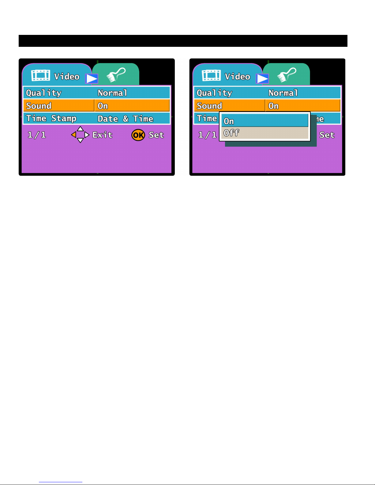
VIDEO MENU - Sound:
This option will activate or deactivate the system’s plug-in microphone to turn audio recording on
or off. Audio recording is very useful in case there is a break-in on vehicle or if the vehicle is
stolen, the system’s microphone can record any conversations or sounds inside the vehicle.
Leaving this option ON will allow audio recording inside the vehicle whenever the system is
activated. If this option is turned OFF, the microphone input will be shut off and audio recording
will be deactivated. The default option is ON.
1. While in “Recording Mode”, Press the MENU button on the remote to enter the VIDEO
Menu.
2. Press the ▼button on the remote to select the “Sound” option.
3. Press the OK button to enter the “Sound” feature setting. Use the ▲▼ buttons to select
either the ON or OFF option. Press the OK button to select the option you wish to change
to.
4. The system will automatically change the setting and return you to the VIDEO menu
NOTE: You may press the EXIT button at anytime on the remote to exit the menu settings if you
do not wish to change any of the options. Exiting the menu will not change any of the
settings on the system.
If the system’s microphone is not plugged in, then there will be no audio recording at all
and turning this option on or off will have no effect.
Audio recording will increase the overall video recording file size when they are saved to
the system’s SD card.
Page 26
26
OPERATION
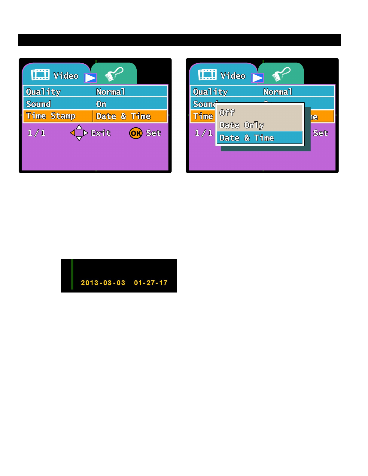
VIDEO MENU – Time Stamp:
This option controls the Time & Date stamp that is recorded onto all of the system’s video files
when the recordings take place. If this option is turned OFF, the Time and Date will not be
displayed on any of the recorded video files and will not be displayed on the LCD monitor when
the system is in Record Mode. If the DATE ONLY option is selected, then the date (yyyy/mm/dd)
will be displayed at the bottom of each video file. If the DATE & TIME option is selected, then
both the time and date will be displayed at the bottom of each recorded video file. The default
option is DATE & TIME.
1. While in “Recording Mode”, Press the MENU button on the remote to enter the VIDEO
Menu.
The Time & Date stamp is recorded
at the bottom right corner on every
video file
2. Press the ▼button on the remote twice to select the “Time Stamp” option.
3. Press the OK button to enter the “Time Stamp” feature setting. Use the ▲▼ buttons to
select either the OFF, DATE ONLY or TIME & DATE option. Press the OK button to
select the option you wish to change to.
4. The system will automatically change the setting and return you to the VIDEO menu
NOTE: You may press the EXIT button at anytime on the remote to exit the menu settings if you
do not wish to change any of the options. Exiting the menu will not change any of the
settings on the system.
Page 27
27
OPERATION
NOTE:
If you choose SINGLE, the system will automatically dele
te
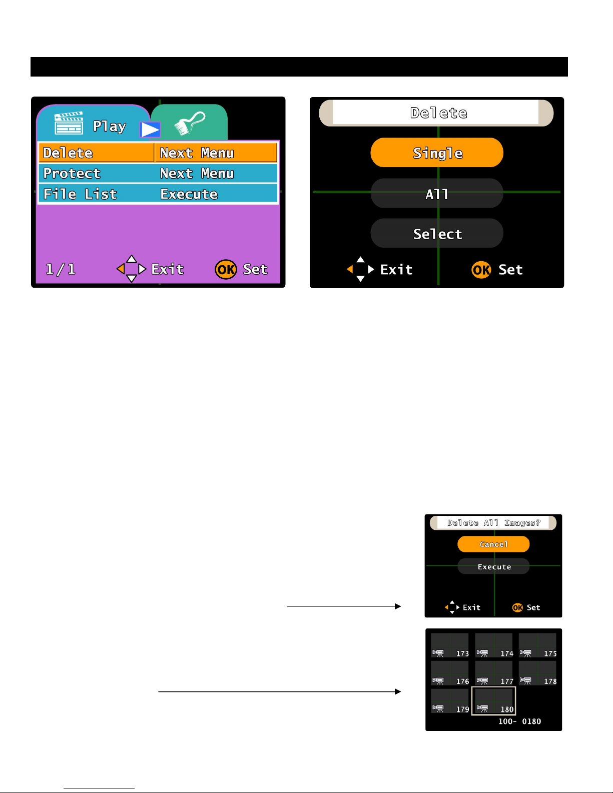
PLAY MENU - Delete:
This option will allow you to delete any of all of the recorded video files. There are three options
under the Delete feature: SINGLE, ALL and SELECT. Choosing the SINGLE option will allow
you to delete the most current recorded video file. Choosing the ALL option will allow you to
delete all recorded video files from the SD card. Choosing the SELECT option will allow you to
select which video file you want to delete.
1. While in “Playback Mode”, Press the MENU button on the remote to enter the PLAY Menu.
2. The “Delete” option is the first option selected in the menu.
3. Press the OK button to enter the “Delete” feature setting. Use the ▲▼ buttons to select
either the SINGLE, ALL or SELECT option. Press the OK button to select the option you
wish to change to. (You can also press EXIT to return to the Play Menu)
the most current recorded video file
If you choose ALL, the system will prompt you to Cancel or
Execute. If you choose to “Execute” the system will delete
all recorded files from the SD card. Choosing “Cancel” will
take you back to the previous menu.
If you choose SELECT, the system will take you to a
selection menu that displays a list of all of the recorded
files. You can use the ▲▼◄► buttons to navigate
through the recordings. Press the OK button to delete the
selected file.
4. Press EXIT on the remote and the system will update the setting
and return you back to the PLAY menu.
Page 28
28
OPERATION
NOTE:
If you choose SINGLE, the s
ystem will
prompt you to Set
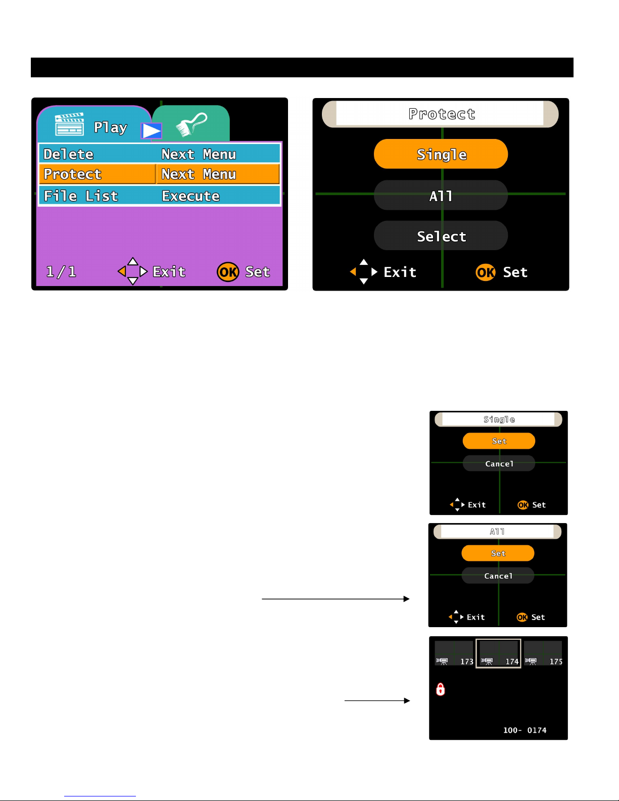
PLAY MENU - Protect:
This option will allow you to Save or “Protect” any or all of the recorded video files and prevent
them from being deleted even when the system is continuously recording. There are three
options under the Protect feature: SINGLE, ALL and SELECT.
1. While in “Playback Mode”, Press the MENU button on the remote to enter the PLAY Menu.
Press the ▼ button to select the “Protect” option and press OK to enter the option.
2. Use the ▲▼ buttons to select either the SINGLE, ALL or
SELECT option. Press the OK button to select the option. (You
can also press EXIT to return to the Play Menu)
or Cancel. If you choose “Set” the system will protect the
most current recorded video file. Choosing “Cancel” will
take you back to the previous menu.
If you choose ALL, the system will prompt you to Set or
Cancel. If you choose “Set” the system will protect all
recorded files on the SD card. Choosing “Cancel” will take
you back to the previous menu.
If you choose SELECT, the system will take you to a
selection menu that displays a list of all of the recorded
files. You can use the ▲▼◄► buttons to navigate
through the recordings. Press the OK button to protect the
selected file. (A red Padlock icon will appear on the left
side of the screen to show the file is protected)
3. Press EXIT on the remote and the system will update the setting
and return you back to the PLAY menu.
Page 29
29
OPERATION
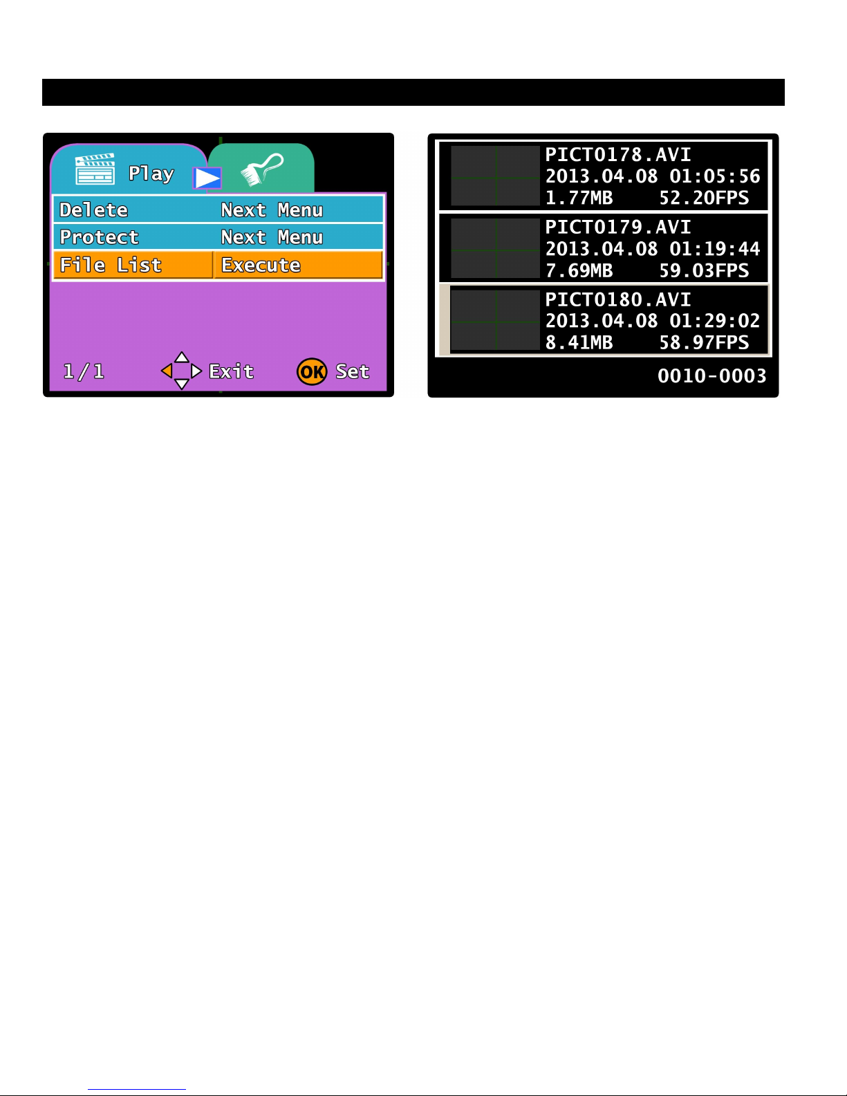
PLAY MENU - File List:
This option will allow you to select a specified video file for playback. Once the option is
selected, the system will go into a preview list and allow you to look through every individual
recorded video file. Each file will have its own specified time and date stamp to help you locate
which file you are looking for. Once you locate the video file you are looking for, you can select it
and the file will begin playback.
1. While in “Playback Mode”, Press the MENU button on the remote to enter the PLAY Menu.
2. Press the ▼button twice on the remote to select the “File List” option.
3. Press the OK button to enter the “File List” feature setting. Use the ▲▼ buttons to
navigate through the file list and find the specific video file you are looking for. Once
you’ve located the specific file, press the OK button to select the file and begin playback.
NOTE: Once playback has begun, you can use the ▲▼◄► buttons to operate the playback
controls. (Please see the “Playback Mode” section of this manual on Page 21)
Each recorded video file will have a Time & Date stamp and a small thumbnail image in
the list to help you navigate and find the specific file you are looking for.
You may press the EXIT button at anytime on the remote to exit the menu settings if you
do not wish to change any of the options. Exiting the menu will not change any of the
settings on the system.
4. Once the video playback is complete, you can the EXIT button and the system will take you
back to the File List menu
Page 30
30
OPERATION
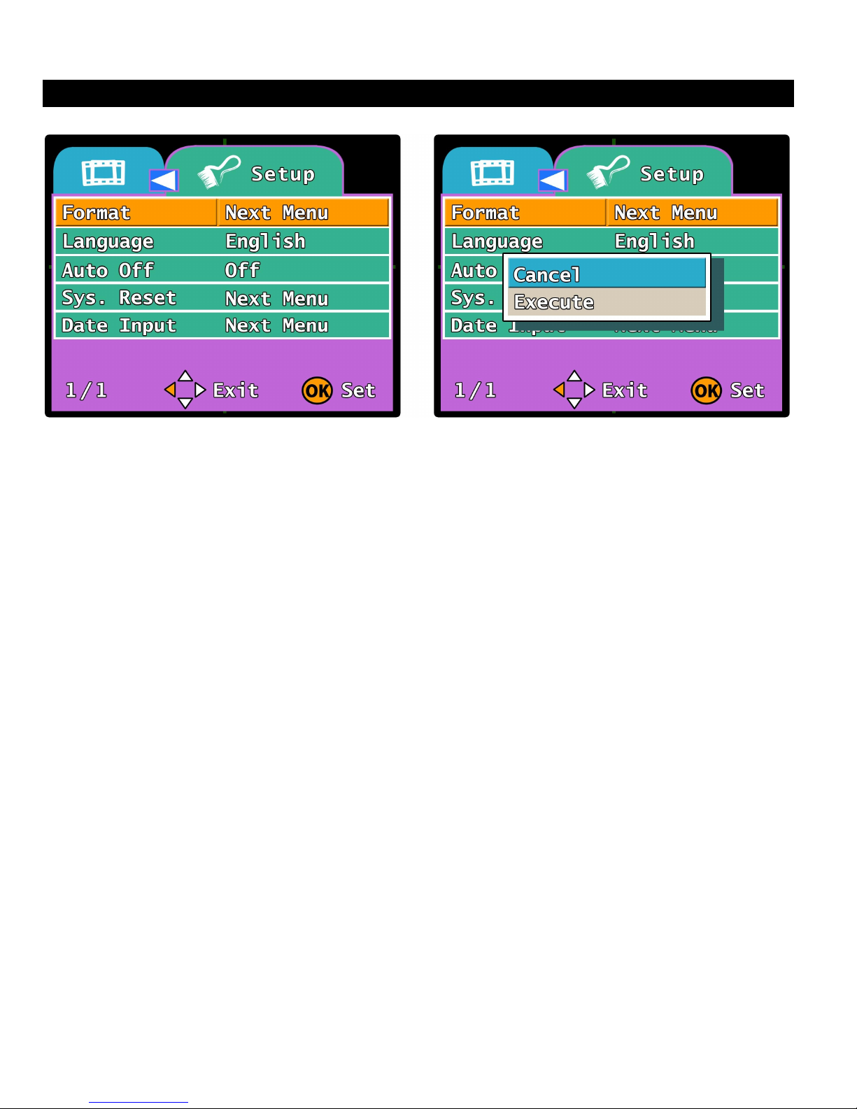
SETUP MENU - Format:
This option allows you to Format the SD Card to FAT32 format and allow the UBB-4.CQ to store
more recordings onto the SD card.
1. While in “Playback Mode” or “Record Mode”, Press the MENU button on the remote to enter
the VIDEO or PLAY menu. Press the ►button to switch to the SETUP menu.
2. The “Format” option is the first option selected in the menu.
3. Press the OK button to enter the “Format” feature setting. Use the ▲▼ buttons to select
Cancel or Execute. Press the OK button to set the option.
NOTE: If you choose “Execute” the system will automatically erase all files on the SD card and
reformat the SD card for better storage capacity. Choosing “Cancel” will take you back to
the SETUP menu.
Once the Execute function is chosen and the system reformats the SD card, all files and
information that was on the SD card will be erased and cannot be retrieved again.
Please make sure to double check any files on the SD card that you wish to save before
choosing this option.
4. Once the reformatting is complete, the system will automatically take you back to the SETUP
menu. You can press the EXIT button to exit the setup menu and go back to the Playback or
Recording screens.
Page 31
31
OPERATION
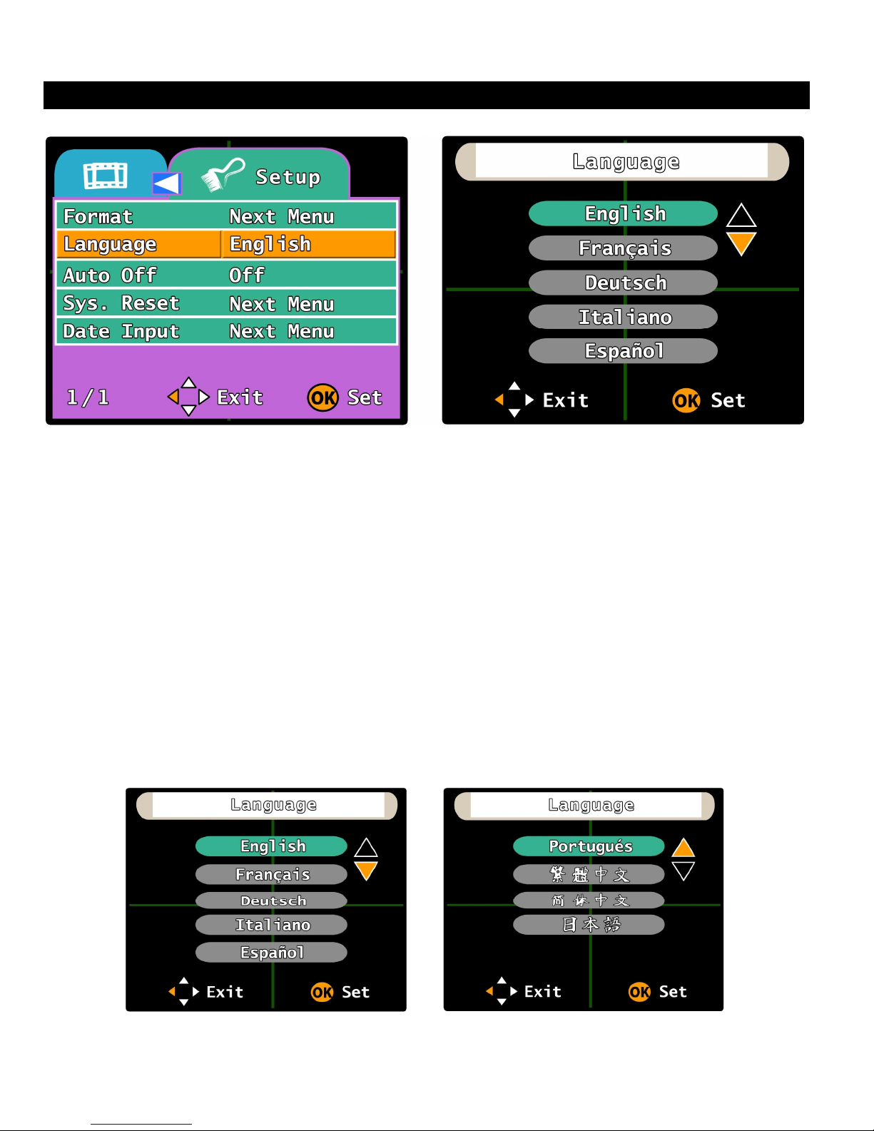
SETUP MENU - Language:
This option will allow you to select which language you want the UBB-4.CQ system to be
displayed in. You can choose from one of nine different languages including: English, French,
Dutch, Italian, Spanish, Portuguese, Chinese (Traditional), Chinese (Simplified) and Japanese.
1. While in “Playback Mode” or “Record Mode”, Press the MENU button on the remote to enter
the VIDEO or PLAY menu. Press the ►button to switch to the SETUP menu.
2. Press the ▼ button to select the “Language” option.
3. Press the OK button to enter the “Language” feature setting. Use the ▲▼ buttons to
navigate through the language options. Press the OK button to select the language that
you wish to change to. (You can also press EXIT to return to the SETUP Menu)
NOTE: Once the language is selected, all system menus will be automatically changed to that
specified language. Languages can be switched at anytime.
4. Once the specified language is set, the system will automatically update and return you back
to the SETUP menu.
Page 32
32
OPERATION
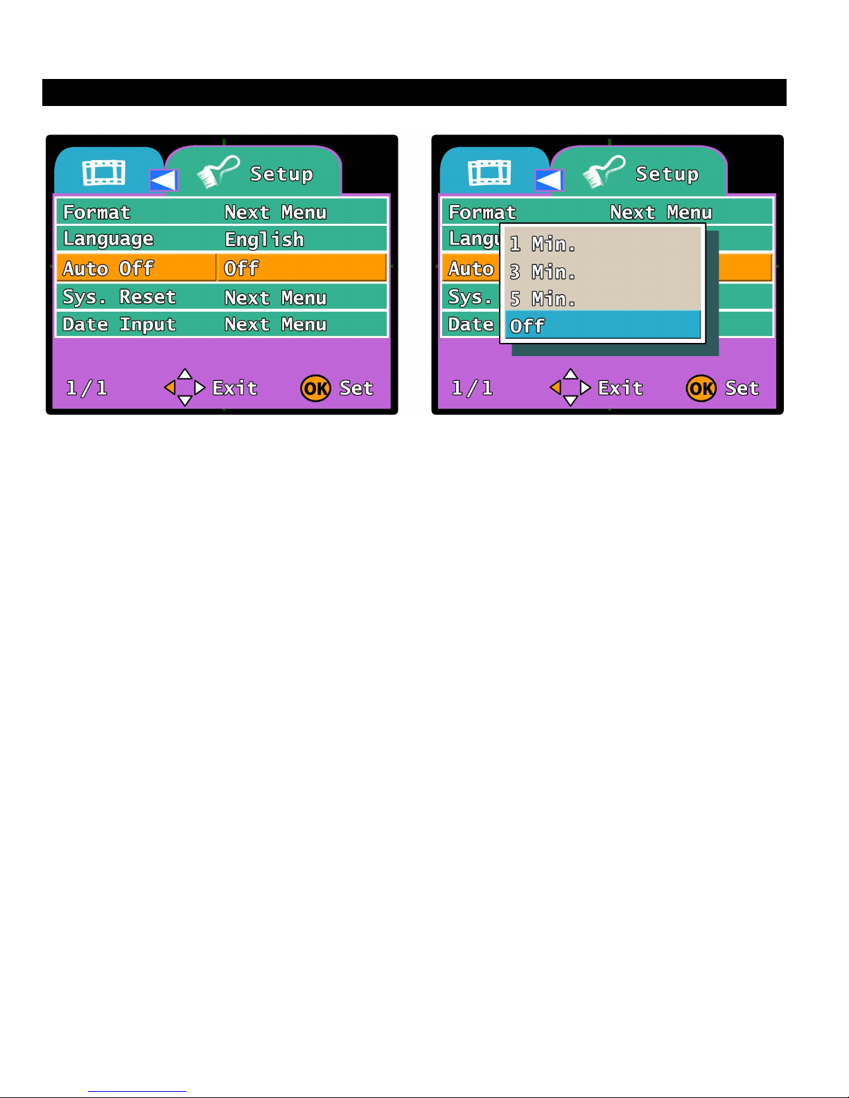
SETUP MENU - Auto Off:
This option allows you to select how long the system will record for after the door is opened and
closed when the ignition is on.
When the ignition is turned on and the door is opened, the system will automatically switch to
the interior camera (VIDEO 3) and begin recording. After the door is closed, the system will
continue to record for the specified amount of time. There are four different settings for this time
interval: 1 Minute, 3 Minutes, 5 Minutes and Off. The Default setting is Off.
1. While in “Playback Mode” or “Record Mode”, Press the MENU button on the remote to enter
the VIDEO or PLAY menu. Press the ►button to switch to the SETUP menu.
2. Press the ▼ button twice to select the “Auto Off” option.
3. Press the OK button to enter the “Auto Off” feature setting. Use the ▲▼ buttons to select
between 1 Minute, 3 Minutes, 5 Minutes and Off. Press the OK button to set the option.
NOTE: If you choose “Off” the system will record for 10 seconds after the door is closed and
then power down to standby mode.
4. Once the selection is complete, the system will automatically take you back to the SETUP
menu. You can press the EXIT button to exit the setup menu and go back to the Playback or
Recording screens.
Page 33
33
OPERATION
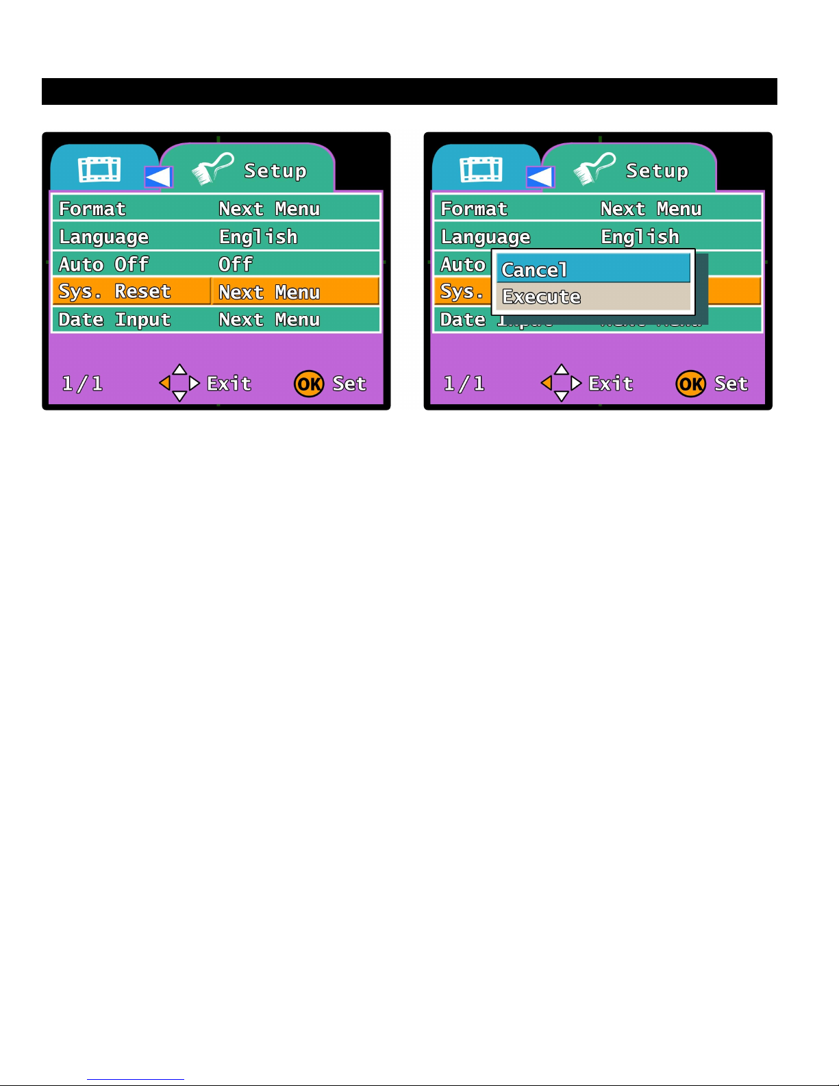
SETUP MENU - Sys. Reset:
This option allows you to reset the UBB-4.CQ system back to all factory default settings. Once
this option is selected, all options that have been changed will be reset and all recorded video
files will be erased from the SD card.
1. While in “Playback Mode” or “Record Mode”, Press the MENU button on the remote to enter
the VIDEO or PLAY menu. Press the ►button to switch to the SETUP menu.
2. Press the ▼ button three times to select the “Sys. Reset” option.
3. Press the OK button to enter the “Sys. Reset” feature setting. Use the ▲▼ buttons to select
between Execute and Cancel.
NOTE: If you choose “Execute” the system automatically reset all options to their default values.
Any options that have been changed will be reset and all recorded video files will be
erased from the SD card. Please make sure to check all of the recordings before you
reset the system to make sure that you will not erase any recordings you wish to keep. If
you select “Cancel” the system will take you back to the SETUP menu.
4. Once the reset is complete, the system will automatically take you back to “Record Mode”
and begin recording immediately.
Page 34
34
OPERATION
NOTE:
There are three lines under the Date Input
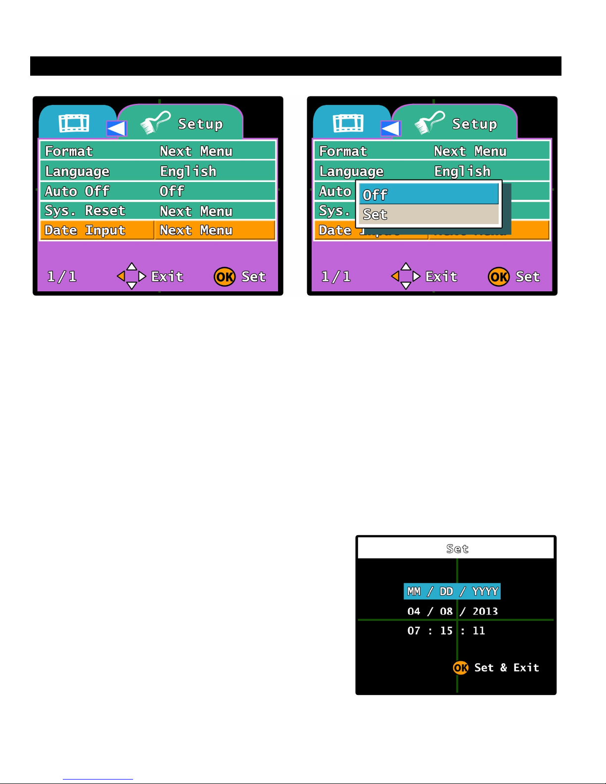
SETUP MENU - Date Input:
This option allows you to set the Time & Date stamp of the UBB-4.CQ system. You can also
select the order of how you want the date to be displayed (Ex. YYYY/MM/DD, MM/DD/YYYY or
DD/MM/YYYY). The Time & Date stamp serves two important functions; One, it lets you know
the time and date that the recording event took place. And two, it makes it easier to cycle
through the recordings in Playback Mode.
1. While in “Playback Mode” or “Record Mode”, Press the MENU button on the remote to enter
the VIDEO or PLAY menu. Press the ►button to switch to the SETUP menu.
2. Press the ▼ button four times to select the “Date Input” option.
3. Press the OK button to enter the “Date Input” option and then use the ▲▼ buttons to
select Set or Off. Choosing “Set” will take you into the Date/Time setting screen to
change the Time & Date stamp. Choosing “Off” will turn the Time & Date stamp
completely off.
setting screen. The first line is the date display
type (YYYY / MM / DD), the second line is the
date setting and the third line is the time setting.
Press the ▲▼ buttons to change the settings
of the current line and then press the ◄►
buttons to move to curser the previous or
next line.
4. Once the Time & Date is set, Press the OK button and the system will automatically save the
settings take you back the SETUP menu..
Page 35
35
OPERATION
SCREEN STRUCTURE:
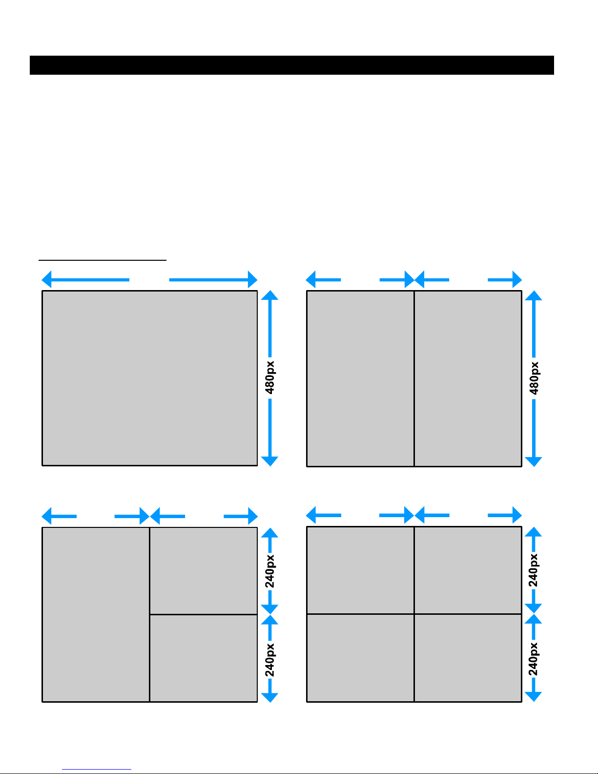
The main display of the UBB-4.CQ system is a standard quad screen. However the system will
auto-detect how many cameras are plugged in and adjust the screen accordingly to how many
cameras it sees.
The primary camera (Usually the front camera VIDEO 1) is always the top left screen in 4camera “quad screen” view, and the left side screen in 3-camera and 2-camera screen views.
If there is only one camera plugged in, whether it is the front, inside or reverse camera, the
screen will only display the one camera that the system detects. Once it sees mores cameras
plugged in, it will re-adjust the window layout to account for the other cameras.
SCREEN STRUCTURE
720px
360px
V1 V1 V4
1 VIDEO INPUT 2 VIDEO INPUT
360px 360px
360px 360px
360px
V3
V1
V4
3 VIDEO INPUT 4 VIDEO INPUT
V1 V2
V3 V4
Page 36
36
OPERATION
SCREEN STRUCTURE: (Continued)
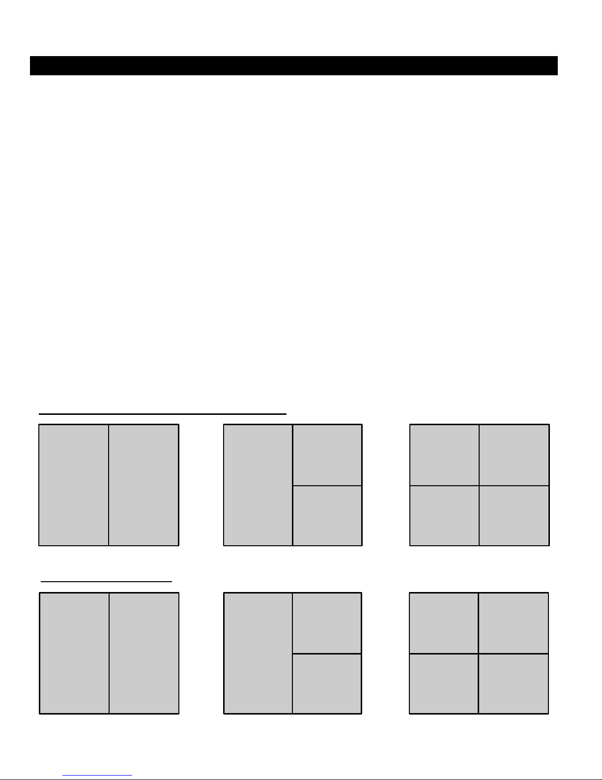
Door Open without Ignition On:
If the door is opened without the ignition on (Simulating a break-in or normal vehicle entry
scenario) the system will automatically switch the security camera (VIDEO 3) to the left or the
upper-left primary camera position on the monitor. The screen structure will remain this way
depending on how long you have the “Auto Off” time set for (Between 10 seconds to 5 minutes).
If the ignition is not switched on before the set time interval runs out, then the system will power
down. If the ignition is turned on before the time runs out, then the system will switch the front
camera (VIDEO 1) back to the primary position.
Ignition On Before Opening Door:
If the door is opened when the ignition is already on (Simulating a passenger pick-up or a
remote start scenario) the system will automatically switch the security camera (VIDEO 3) to the
left or the upper-left primary camera position on the monitor. The screen structure will remain
this way depending on how long you have the “Auto Off” option time set for (Between 10
seconds to 5 minutes).
Ignition Recording:
After the boot up recording is complete, the system will switch the front camera (VIDEO 1) back
to the left or upper left primary camera position on the screen and begin recording immediately
as long as the ignition is on. A new recorded file will be generated every 5 minutes and stored
on the SD card with a time and date stamp.
DOOR OPEN RECORDING (Ignition On/Off)
V3 V1 V3
IGNITION RECORDING
V1 V4 V1
V1
V4
V3
V4
V3
V2
V1
V3
V1
V4
V2
V4
Page 37
37
OPERATION
SCREEN STRUCTURE: (Continued)
EVENT RECORDING:
1. Door Open: This event will switch the security camera (VIDEO 3) to the left or the upper-left
primary camera screen and begin recording. The system will continuously generate a new
recording file every 5 minutes and store it in the on the SD card with its own time and date
stamp.
2. Door Closed: This event will allow the system to record for an additional 10 seconds to 5
minutes (Programmable) after the door is closed and then switch the front camera (VIDEO 1)
back to the left or upper-left primary camera position. The system will store the additional
recordings on the SD card
3. Reverse Recording: This event will switch the reverse
camera (VIDEO 4) to the primary camera screen and begin
recording immediately. Every 5 minutes the system will
generate a new recording file and store it on the SD card
with its own time and date stamp.
4. Reverse Off: This event will allow the system to switch
back to the front camera (VIDEO 1) and begin recording
immediately
REVERSE RECORDING
V4
AUDIO RECORDING:
For audio recording inside the vehicle, the microphone will switch on automatically when the
system is activated either by the Ignition, Dome Light or Reverse triggers. The audio data is
stored on the same *.asf file as the video and they are integrated together into one recording so
there is no need to activate the audio recording separately from the video recording, the system
will activate them both automatically and store it all on the SD card.
SD CARD MEMORY MANAGEMENT:
The UBB-4.CQ comes included with an 8GB SD card to
store the recordings. You can use up to a 32GB SD card if
you wish. The system automatically formats the SD card to
store the recordings. All recordings are stored in a
continuous list format with their own Time & Date Stamp and
file size. All recordings are in order from newest to oldest
and can be deleted from the SD card either in playback
mode from the system itself or from you computer.
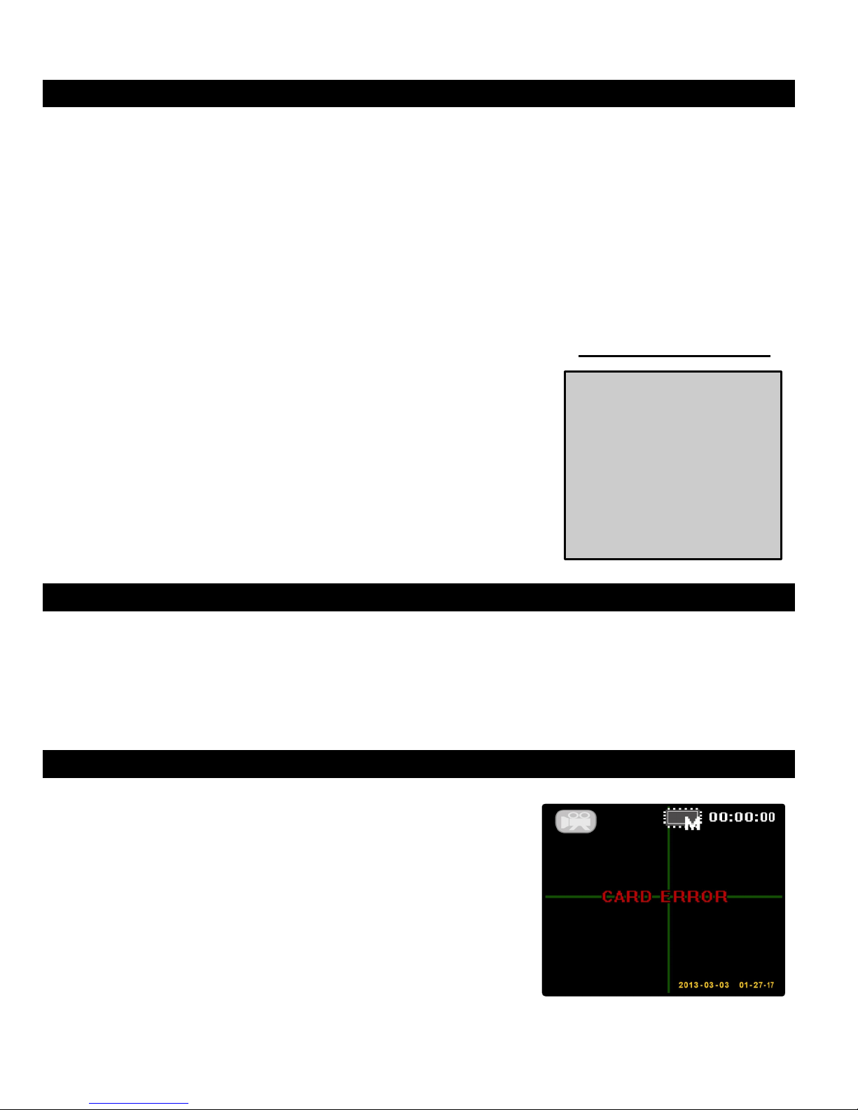
NOTE: If the system is activated without the SD card in
place, a “CARD ERROR” message will appear on
the monitor to let you know
CARD ERROR SCREEN
Page 38

38
TROUBLESHOOTING:
Please read the following helpful tips if you run into any trouble installing this system into the
vehicle. These tips may also be useful if the operation of the system is not functioning properly.
Please make sure that the system is powered up and working properly before reading through
these tips. For normal operation, the unit should activate as soon as the vehicle ignition is
turned on. The LCD monitor should power on and any cameras that are plugged into the system
should be displayed.
SYSTEM DOES NOT TURN ON -or- NO DISPLAY ON MONITOR:
1. Check the systems main power (Yellow) and ground (Black x2) connections are good.
Scrape away any paint or rust on the ground location to make sure it has a good
connection. Also, check to make sure the ignition wire (Red) is hooked up properly to an
ignition source.
2. Check the power and ground connection of the monitor and each camera. The power for
the cameras will be connected to the camera output (Blue) wire on the system’s power
harness. Make sure this connection is good. The power connection for the monitor
should be going to 12 volt ignition.
3. Check the RCA video cables for each camera and make sure they are not spliced or
pinched anywhere along the like. Make sure that are properly connected to the UBB-
4.CQ module. Double check the RCA cable from the monitor as well and make sure it is
not pinched or spliced either.
NOT ALL CAMERAS DISPLAY ON MONITOR:
1. Check power and ground connections of all cameras and make sure they are connected
properly and turning on. If need be, plug the problem camera’s RCA into another monitor
just to test and make sure the video output of the camera is working properly. This will
allow you to find out if there is a problem with the camera itself or the UBB-4.CQ system.
2. Check all RCA connections for the cameras and make sure they are not spliced or
pinched and double check to make sure they are plugged in security to the UBB-4.CQ
system.
CANNOT ACCESS THE SYSTEM MENU:
1. The remote does not require any programming to the system and should work right out of
the box as long as the IR sensor is plugged into the main module. Make sure the IR
sensor has a good connection to the UBB-4.CQ main module and that the cable is not
spliced or pinched.
2. The IR sensor may be mounted in a location where it cannot see the IR eye of the
remote. Check to make sure the remote can be pointed line-of-sight and the IR sensor
and that nothing is blocking it.
3. Check the battery and make sure it is a fresh battery and is installed properly into the
remote.
Page 39

39
TROUBLESHOOTING: (Continued)
NO SOUND ON RECORDINGS:
1. Double check to make sure that the 3.5mm microphone jack is plugged into the unit
correctly and that the cable itself is not pinched or spliced open. Make sure the
microphone is in a good mounting location where all sound can be recorded.
2. In the VIDEO menu, check to make sure that the SOUND option is turned on. If this
option is off, the microphone out is turned off by the system and there will be no audio
recording. (Audio recording is optional and will not inhibit the system from working if this
option is off or if the microphone is not plugged in)
TECHNICAL SPECIFICATIONS:
SPECIFICATIONS:
Supply Voltage: DC 12 Volt
Operational Voltage: 9V ~ 36V
Current Consumption: Working Mode: 400mA - Standby Mode: 10mA
TV System NTSC / PAL
Resolution: QVGA 320 × 240, 30 fps
Video Inputs: 4 RCA (1.0V ± 20m Vp-p, 75 Ohm)
Video Outputs: 1 RCA (1.0V ± 20m Vp-p, 75 Ohm)
Video Encode Method: MPEG4
Video File Format: Advanced Systems Format (.asf)
Audio Input: Microphone (3.5mm headphone jack) stereo line-in
Audio Output: Stereo line-out
Audio Encode Method: ADPCM
Audio Sampling: 44100 bps
Storage Temperature: -4°F - 185°F (-20°C - 85°C)
Operating Temperature: 32°F - 158°F (0°C - 70°C)
Control Module Dimensions (MM): 142 (L) × 101 (W) × 33 (D)
DISCLAIMER:
Under no circumstances shall the manufacturer or distributor of the UBB-4.CQ system be held liable for
consequential or incidental damages sustained in connection with the use of the UBB-4.CQ Mobile DVR
system. The UBB-4.CQ is designed as a safety enhancement device and is in no way intended as a
replacement for rear-view mirrors, side-view mirrors or physically checking the surroundings when
backing up, parking or driving the vehicle. Always check surroundings for safety when operating the
vehicle! Objects on the monitor are closer than they appear. For the installation, modification of certain
parts of the vehicle may be required. It is the sole responsibility of the vehicle owner to check and verify
any and all State or Federal Motor vehicle codes with regards to modifications of vehicle bumper or any
systems in the vehicle. The manufacturer of the UBB-4.CQ assumes no liability or responsibility
whatsoever with regards modifications of the vehicle bumpers or any other equipment in the vehicle.
REV: B 04-15-2013
Page 40

40
TECHNICAL SUPPORT: (800) 998-6880
Monday - Friday 8:00am - 4:30pm Pacific Std. Time
E-mail: [email protected]
CRIMESTOPPER SECURITY PRODUCTS, INC.
1770 S. TAPO STREET, SIMI VALLEY, CA. 93063
© 2013 Crimestopper Security Products
Web Site: www.crimestopper.com
REV: B 04-15-2013
 Loading...