

Page 1
C4evo - INSTALLATION GUIDE
V 1.2
04/03/2011
Page 2

Table of contents
Preface ............................................................................................................ 3
Warnings and notices ...................................................................................... 3
1. Hardware features ...................................................................................... 4
2. Hardware description .................................................................................. 5
2.1. Front ..................................................................................................... 5
2.2. Back ...................................................................................................... 5
2.3. Inside .................................................................................................... 6
3. Preparing/installing the device ..................................................................... 7
3.1. Open the device to insert a sim card ....................................................... 7
3.2. Connect the GSM/GPS external antenna ............................................... 8
3.3. Choose the appropriate location for mounting ...................................... 8
3.4. Pin out & Wires description ................................................................... 8
3.5. Plug the device to the external battery .................................................. 9
4. Inputs activation threshold ......................................................................... 9
5. LEDs sequences ......................................................................................... 10
6. Support ..................................................................................................... 10
Page 3

Preface
The information contained in this installation guide is subject to changes in order to
improve the reliability, design or features without prior notice. Mobile Devices reserves the
right to make changes in the content without obligation to notify any person or
organisation of such changes or improvements. Mobile Devices can in no event be held
liable for technical or editorial errors or omissions herein, nor for incidental, special or
consequential damages from the furnishing, performance or use of this installation guide.
Please contact our technical support for current updates and supplemental information
concerning the use and operation of this or other Mobile Devices products.
Warnings and notices
Please read the installation guidelines, as well as the safety and operating instructions
before operating your device. Follow all instructions and heed all warnings in the installation
guide.
Page 4

1. Hardware features
C4E
Performance Processor ARM 11 - 500MHz
RAM 64 Mbytes
NAND Flash 256 Mbytes
Power supply External power supply 8-
32V
●
External voltage
measurement
8-32V
Li-ion battery charger
●
Li-ion battery option (900mA.h)
Communication GSM receiver
●
GSM antenna External
Positioning GPS receiver
●
GPS antenna External
Interface & Telematics
features
USB (2.0 Host/Slave) powered (limited to 350 mA on 5V)
when connected to external power
not powered on internal battery
Input Ignition (active high) alarm (active
low) and 1 input active low.
Output 2 (active low 300mA driving
current )
3D Accelerometer ±2g, ±8g
3 axis Gyroscope Please contact us
1-wire
●
LEDs 2
Environmental Connectors microFIT 8 pins
Mini-USB
Fakra connectors for the antennas
Operating temperature * -20/+60°C (contact us for extended
range)
Dimensions 66x66x24
SIM card slot
*without battery
Page 5
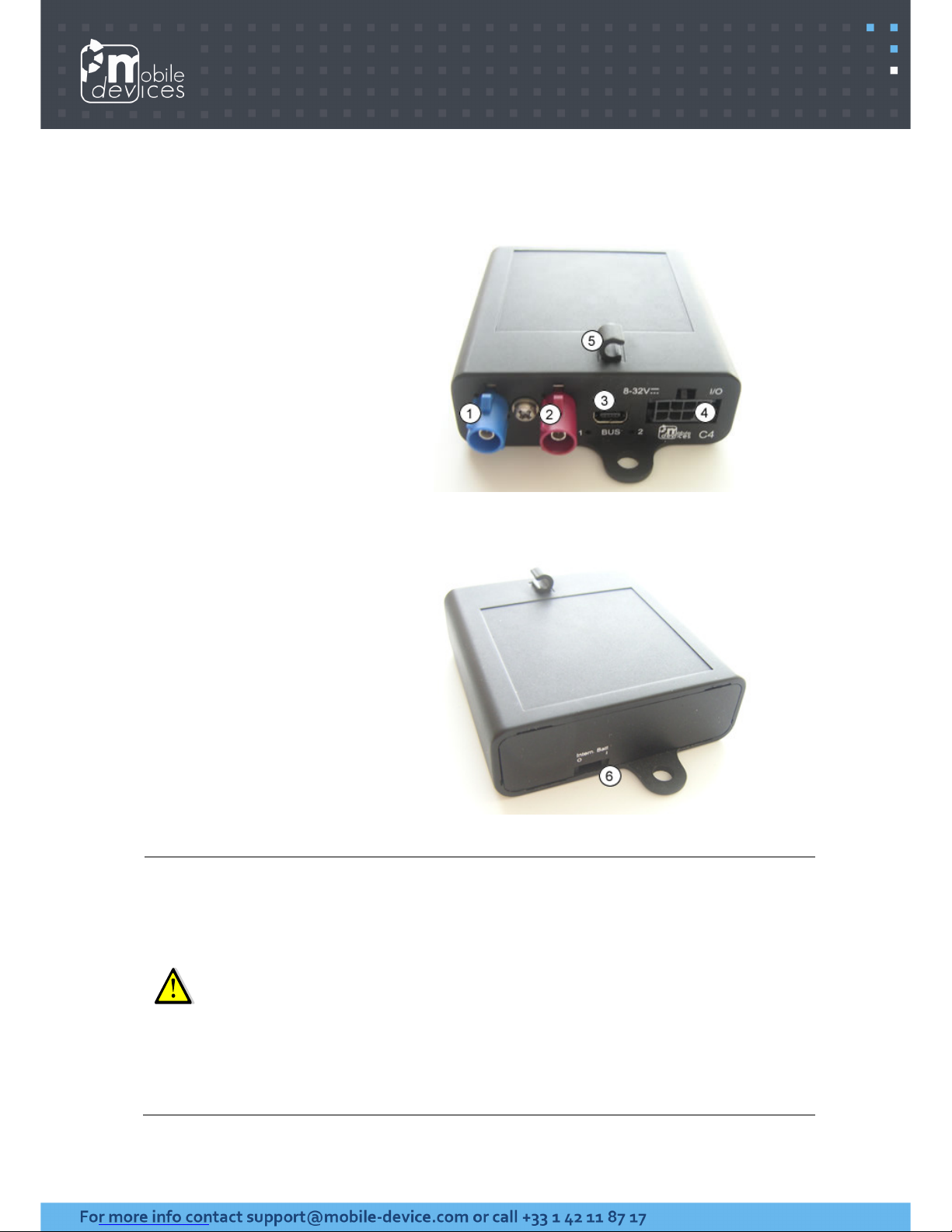
2. Hardware description
2.1. Front
1. GSM connector
2. GPS connector
3. USB connector
4.
Molex (8pins) connector
5. USB cable Hook
2.2. Back
6. Inner battery switch
Move the switch
The switching ON of the internal battery requires a running
10 seconds after ignition (the led 4 must be lit then unlit).
Move the switch
The switching OFF of the internal battery is instant. Thus, don't switch off the
internal battery if th
battery.
inwards
(I) to activate the internal battery.
system. This is about
outwards
(O) to deactivate the internal battery
e device is running without be connected to an external
.
Page 6
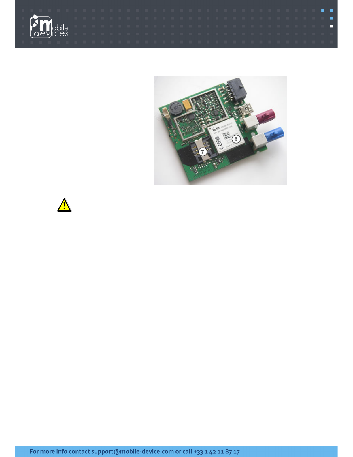
2.3. Inside
7. SIM holder
8. GSM/GPS module
The SIM card PIN code must be deactivated.
Page 7
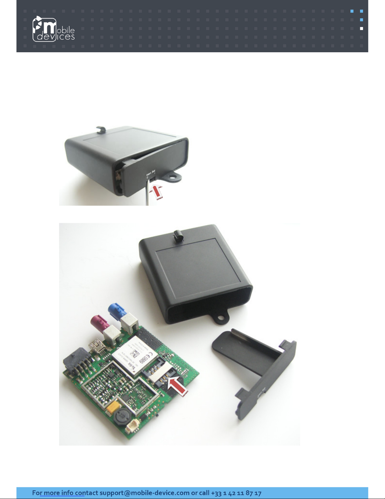
3. Preparing/installing the device
3.1. Open the device to insert a sim card
Insert a flat screwdriver into the inner battery switch hole and pry it to remove the back
cover. Afterwards pull on the PCB to release it.
Page 8
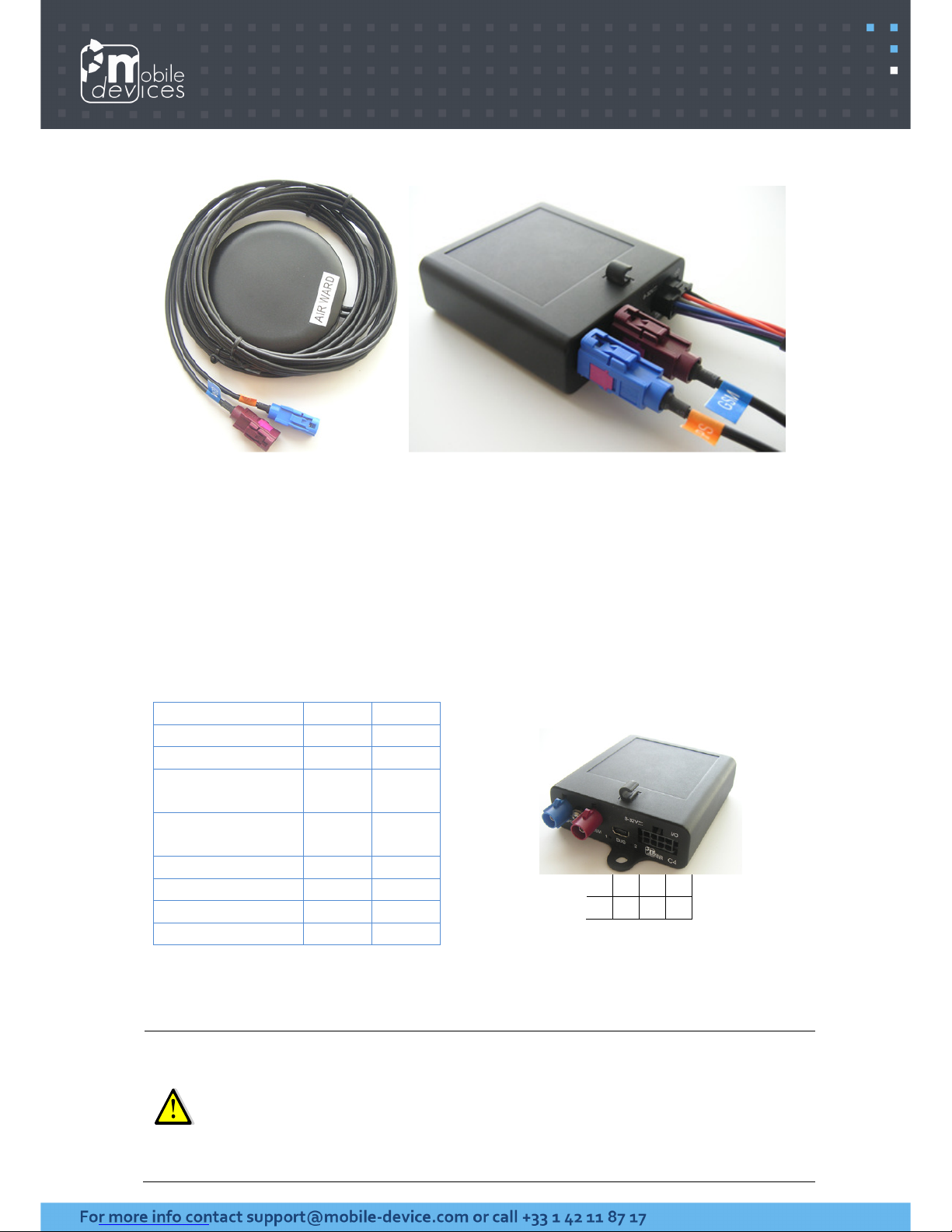
3.2. Connect the GSM/GPS external antenna
3.3. Choose the appropriate location for mounting
The ideal location for mounting the device is under the dashboard. However, some types of
coated windshields, as well as windshields with an in-screen heating system can block GPS
signals. External antenna should never be covered by any kind of object or material,
especially not by metal or aluminium. Transmission and reception of GPS signal is however
not hindered by plastic or normal glass. Moreover, put at least 20 cm between the antenna
and a speaker.
3.4. Pin out & Wires description
Signal Pin Colour
VBAT_EXT 1 Red
GND 2 Black
IN1_IGNITION
(VBAT) 3
White
IN2_ALARM
(GND) 4
Orange
IN3 (GND) 5 Green
ONE_WIRE 6 Grey
DIG_OUT1 7 Purple
DIG_OUT2 8 Blue
8 6 4 2
7 5 3 1
Power supply may be derived directly from the vehicle’s main power or from the board
installation. In the first case, it is an absolute must that a fuse on the main cable is present.
Ignition wire must always be connected to the vehicle’s ignition OR tied with the
permanent positive to the vehicle’s battery.
Ground must be always connected first. It is mandatory to add a fuse (2A) to the
permanent positive. The closer to the connection point with vehicle power.
Page 9

3.5. Plug the device to the external battery
The device must have a direct connection with the main power (external battery). Mobile
Devices advise against the use of intermediate system.
1. Check that inputs 2 and 3 are free (not connected).
2. Plug the device (black wire) to the ground of the external battery.
3. Plug the device (red wire) to the permanent positive of the external battery.
4. Plug the device (white wire) to the ignition (after contact).
In some case, the use of a circuit breaker can let the ignition (after contact) active. Thus, the
device will be ON indefinitely. So, it’s important to find a signal where the ignition can be
ON or OFF.
Moreover, it is imperative to insulate the GPS antenna in order to avoid it get in touch with
the car’s chassis.
The device should be always plugged to :
• The ground of the external battery.
• A ground point defined by the vehicle manufacturer.
A circuit breaker should never be enabled as long as:
• Ignition is active.
• Ignition goes OFF since less than 2 minutes. This is the time for the device
to do a proper shutdown.
It is mandatory to add a fuse (2A) to the permanent positive. The closer to the
connection point with vehicle power.
4. Inputs activation threshold
Here are inputs activation thresholds (voltage).
• Input2 (negative) is active from approx. 0 to 2V (disabled if >2V)
• Input3 (negative) is active from approx. 0 to 2V (disabled if >2V)
Note: Range voltage on inputs is 0-30V
Page 10

5. LEDs sequences
Green LED (Soft) Red LED (System)
Sequence Meaning Sequence Meaning
No GPRS/No
GPS
3 times (50ms ON/100ms
OFF)
3550ms OFF
C4E OFF OFF
No GPRS/Fix
GPS
2 times (50ms ON/100ms
OFF)
3700ms OFF
Ext.
Power/Run
ON
GPRS OK/No
GPS
1 time (50ms ON/100ms
OFF)
3850ms OFF
Int. Bat/Run 200ms ON/800ms OFF
GPRS OK/Fix
GPS
2000ms ON
2000ms OFF
Shutdown 5ms ON/2000ms OFF
Idle/Sleep
twice (5ms ON/50ms
OFF)
1895ms OFF
6. Support
For all questions not related in this installation guide, please contact the support team by
email at [email protected]
 Loading...