

Page 1

Ver
1.0 - 2017
MPT-100
I N S T R U C T I O N M A N U A L
Mobile Create Co., Ltd.
Page 2
- 2 -
■Newly developed Ultra-wide range coverage
The MPT-100U allows you to make calls anywhere within the coverage area of the cellular communication network.
Since conventional blind zones such as areas outside radio communication areas and places between buildings
are significantly reduced, you can make calls with a wider coverage area.
■High voice quality
The MPT-100U has a loud speaker with the advanced VoIP technology, so you get high voice quality rather than
conventional two-way radios. The microphone sensitivity is also adjustable to make for clear sound.
■Various calling modes
The MPT-100U has various calling modes to support your business.
■Convenient shortcut buttons
You can set shortcuts for the functions which are used frequently such as for the calling modes or setting screens.
Just press the Shortcut Button to make a call quickly.
■Applicable for 12V and 24V Vehicle
The MPT-100U supports both 12V and 24V power supplies. A DC/DC converter isn’t needed when using 24V. The
device goes into low power saving mode when powered off so as to reduce battery use when the car is parked for
a long time.
■GPS fleet management
Installing the optional GPS antenna allows you to manage vehicle locations.
Working Status such as "Loading" and "Unloading" which are required for your fleet management, can also be
changed by operating the Multi-function Microphone.
Product Features
The GPS service needs to be applied for. Contact your dealer for details.
Page 3

- 3 -
PLEASE OBSERVE FULLY
Be sure to observe the following precautions fully for the safe and proper use of this product:
WARNING
This sign indicates a hazardous situation which could result in serious injury or death if
ignored or incorrectly handled.
CAUTION
This sign indicates a hazardous situation which could result in physical or property
damage if ignored or incorrectly handled.
This symbol indicates bans which must be fully complied.
This symbol indicates precautions which need to be fully observed.
This symbol indicates notes which are requested to be considered.
WARNING
Do not operate the microphone while driving a car.
Before operating this product, a driver shall stop the car in a safe place.
Do not install or operate this product in airplanes and hospitals, or it could affect
electronic and medical devices.
Do not install or operate this product in places where inflammable gas is generated, or
it could cause an ignition accident.
Cardiac pacemaker users shall not use this product, because it could affect
pacemakers, causing an accident due to the malfunction of such devices.
Use this product away from automatic control equipment such as automatic door and
fire alarm systems, or the radio waves generated by this product could affect such
equipment, causing an accident due to malfunction.
Install this product to avoid a risk of pinching or damage the power code.
It could cause a fine, overheating or ignition accident.
Safety Precautions
Page 4
- 4 -
PLEASE OBSERVE FULLY
Be sure to observe the following precautions fully for the safe and proper use of this product:
WARNING
Do not install or operate this product in a place which may obstruct the operator’s front
vision or interfere with the operation, or it could cause an injury, an accident, or a failure.
Pay attention to the speaker volume while driving so that the sound outside the car can
be heard. Failure to do so could cause an injury or accident.
Do not disassemble or modify this product, or it could cause an injury, an accident, or a
failure.
CAUTION
Do not install or operate this product in places which are subject to direct sunlight, or it
could cause plastic case deformation or discoloration, or a failure.
Do not install or operate this product in places which are subject to rain or water splash.
It could cause failure since this product are not anti-dust or waterproof treatment.
Do not give an impact to or throw this product, or it could cause a failure.
Do not connect this product to any devices other than the specified ones, or it could
cause a failure.
Keep this product away from magnetic cards such as cash cards, or the data on them
may be lost.
Do not use thinner or alcohol when cleaning this product, or it could cause plastic case
deformation or discoloration, or a failure.
Safety Precautions
Page 5

- 5 -
For the proper use of this product
■ This product performs communication using a cellular network. The scope of the warranty of this product does not
include cellular networks. Be sure to understand the properties of this system and harness its benefits under the
responsibility of the user.
■ Use only accessories sold by Mobile Create. Do not use commercially-available or self-built accessories such as
GPS antenna, USB extension cable, or the product will not be covered under warranty.
■ The housing is made of ABS resin. Do not throw or drop this product during transportation, or it may break. In
addition, do not remove screws from this product to disassemble it, or it could cause performance degradation or
failure which is not covered under the product warranty.
■ This product and accessories are not waterproof nor dustproof. It will be out of warranty if the failure caused by
water or dust.
■ This product is designed and manufactured only for standard commercial communications. Do not use this
product which is required for special quality or reliability such as medical, disaster-prevention, or security device,
for which failure or malfunction affects life support or property significantly.
■ Do not install this product in places which are subject to direct sunlight in spite of designing for vehicles, trucks and
so forth, or it could cause performance degradation or failure.
*Recommended usage environment temperature: 32°F to +113°F (0°C to +40°C)
■ Do not remain MIC code strongly extended or it could cause code disconnection.
■ Leaving stains on this product for a long time may cause flaking of the plating or paint. Wipe with a dry soft cloth
periodically.
■ When talking, keep the microphone approximately 2 inch away from the mouth. Talking at a close distance to the
microphone could cause cracking or distortion of the voice transmitted to the other party.
■ Using this product in places where cellular signal is poor such as in a tunnel or garage and the influence of
communication line conditions (such as network line construction and crossed lines) may cause the interruption
of the flow of conversing voices during a call.
■ The firmware of this product cannot be reverse-engineered, reverse-assembled, or reverse-complied. It also
cannot be modified or revised.
■ No notices of intellectual property rights such as copyright, patent, utility model, and trademark described for
this product can be deleted or modified.
Points to be noted before using this product
We assume no responsibility whatsoever for any direct, indirect, or incidental damage to you or a third party
caused by the use of this product under your own responsibility.
When using this product, be sure to take all possible measures such as by paying sufficient attention to the
usage environment and conditions and by taking safety and reliability measures including malfunction
prevention and preventing the spread of fire.
Page 6

- 6 -
For FCC part 15 subpart B
■ Changes or modifications not expressly approved by the party responsible for compliance could void the user’s
authority to operate the equipment.
■ Peripheral equipment: Dedicated device by Mobile Create
■ NOTE: This equipment has been tested and found to comply with the limits for a Class B digital device, pursuant
to part 15 of the FCC Rules. These limits are designed to provide reasonable protection against harmful
interference in a residential installation. This equipment generates, uses and can radiate radio frequency energy
and, if not installed and used in accordance with the instructions, may cause harmful interference to radio
communications. However, there is no guarantee that interference will not occur in a particular installation. If this
equipment does cause harmful interference to radio or television reception, which can be determined by turning
the equipment off and on, the user is encouraged to try to correct the interference by one or more of the following
measures:
- Reorient or relocate the receiving antenna.
- Increase the separation between the equipment and receiver.
- Connect the equipment into an outlet on a circuit different from that to which the receiver is connected.
- Consult the dealer or an experienced radio/TV technician for help.
■ This device complies with Part 15 of the FCC Rules. Operation is subject to the following two conditions:
(1) this device may not cause harmful interference, and
(2) this device must accept any interference received, including interference that may cause undesired
operation.
Page 7
- 7 -
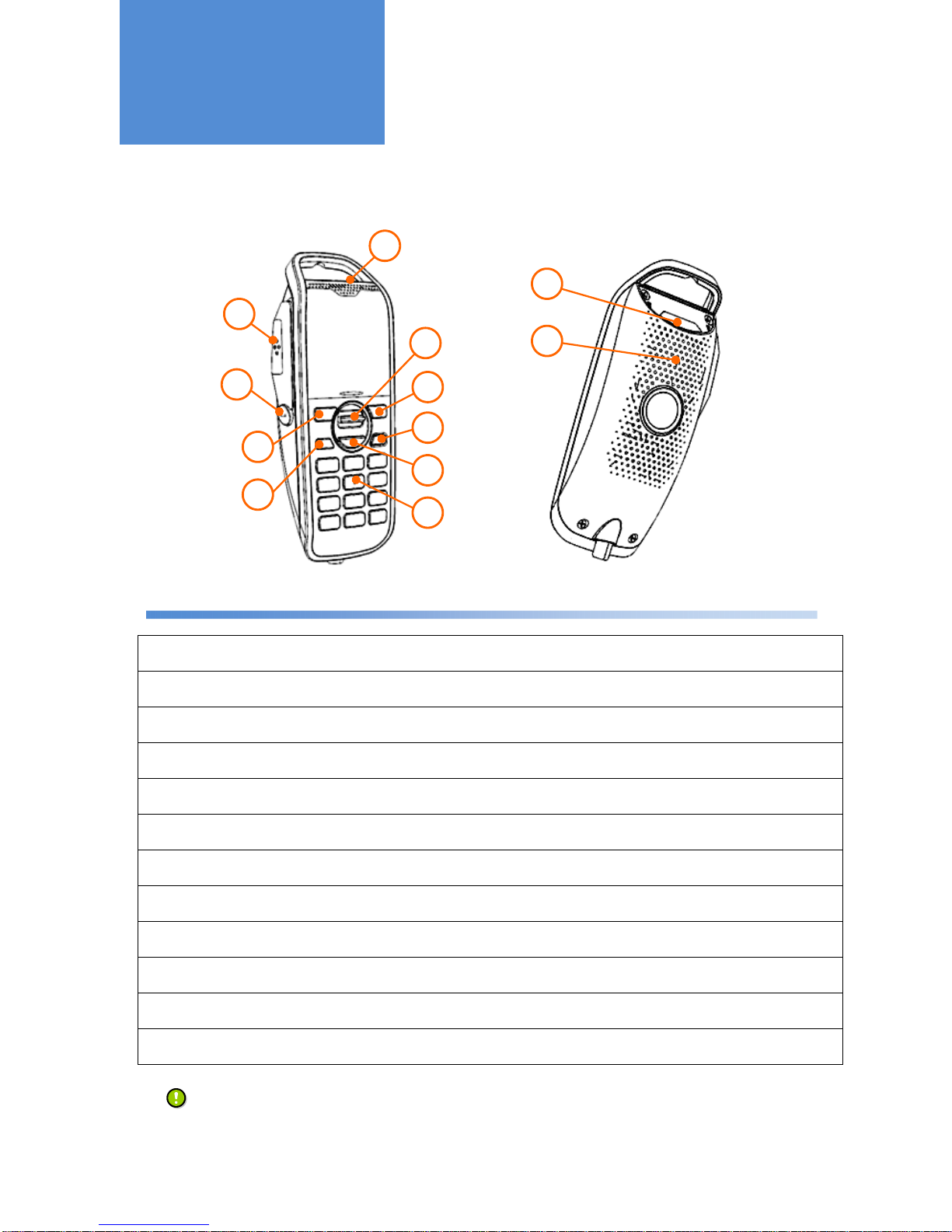
Microphone
Front
Rear
①
PTT Button
Pressing this PTT Button starts making a call.
Pressing this PTT Button during a call transmits sound to a counterpart radio.
②
Shortcut Button
Pressing this button enables registered call modes or menus.
For more details of Shortcut Button, refer to "Useful Functions- Shortcut" on page 18.
③
Left Button
This button is used mainly when switching call modes and returning to the menu screen.
④
Home Button
Pressing this button returns to the home screen.
⑤
Up/Down Button
This button is used mainly when adjusting sound volume and selecting menu functions.
⑥
OK Button
This button is used mainly when finalizing a choice and making a call.
⑦
Right Button
This button is used mainly when selecting menu functions.
⑧
Power Button
This button is used when turning the power on and off. (*1)
⑨
Numeric Keypad
This keypad is used when entering a number during individual calls.
⑩
Microphone
Talk toward this port during a call.
⑪
LED Light
The LED lights flicker when the call ends.
⑫
Speaker
The sound transmitted from a counterpart radio as well as sound effects are played in silent mode.
*1: It works during the Power On Trigger is "Power Button" only.
Functions of Parts
10
1
2
3
4
11
12
5
7
6
8
9
Page 8
- 8 -
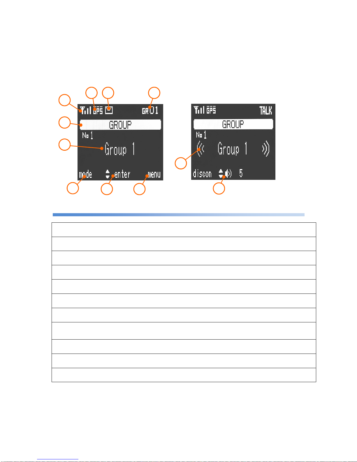
Display screen
①
3G RSSI
3G Received Signal Strength Indicator is displayed on a scale of one to four.
②
GPS RSSI
GPS Received Signal Strength Indicator.
③
Message
The icon is displayed when you have unread text messages.
④
My Group /
My Channel
The Group/Channel that you now belong to can be displayed.
⑤
Call Mode
The current call mode is displayed.
⑥
Call Mode Detail
The number of the radio ID which is selected for the current call mode is displayed.
⑦
Function of the Left Button
Action
The action of the Left Button is displayed. This button is used mainly when switching of
call modes.
⑧
Function of the Up and
Down / OK Button Action
The action of the Up and Down / OK Button is displayed.
This button is used mainly when selecting menu items and during a call, adjusting
sound volume.
⑨
Function of the Right
Button Action
The action of the Right Button is displayed.
⑩
Call Status
These are displayed during a call.
⑪
Sound Volume
The sound volume of the Speaker which is set to be output is displayed.
During a call, pressing the Up or Down Button changes the sound volume.
7
8
9
10
11
1
5
6
Home screen
Screen during a call
2 3 4
Page 9

- 9 -
Main body (Front)
(Rear)
①
Power Button / Volume
Pushing the button to turn the power on and off. (*4)
And turning this knob left and right adjusts the sound volume.
②
GPS LED
During the reception of GPS signal, this LED turns on.
③
LINK LED
While the cellular network is functioning, this LED keeps turning on.
④
TALK LED
During a call, it turns on. While the voice data are being transmitted or received, it flickers.
⑤
External Speaker Jack
Connector for an external speaker.
Use an 8Ω speaker. It is recommended to use nominal 5W or greater. (*1/*2)
⑥
MIC Connector
This port is to connect with the Multi-function Microphone. (*2)
⑦
GPS Connector
This port is to connect with the GPS antenna. (*2)
⑧
External Connector
I/O connector for external peripherals. (*2/*3)
⑨
USB Connector
Connecting with the communication module. (*2)
⑩
Power Connector
Connecting with the power cable. (*2)
*1: This product cannot connect with earphone or headphone or it may cause the product damage.
*2: Use connectors that Mobile Create appoints.
Using connectors which are not appointed by Mobile Create, it may cause the product damage.
*3: To use the external connector, the product needs to be customized. Contact your dealer for details.
*4: It works during the power on trigger is "Power Button" only.
1
2 3
4
5
6
7 8 9
10
Functions of Parts
Page 10

- 10 -
Turning the power on
1
: The start-up method differs depending on the setting, which is available in the following three types:
"Power Button" "External Trigger" and "Always On".
2
: The screen lights up and the home screen is displayed.
Turning the power off
1
: If the power control mode is “Power Button”, hold down the Power Button on the main body or the
microphone for 2 seconds. If the mode is “External Trigger”, turn off the engine key.
2
: The screen goes out and the power is turned off.
Power Button Mode
OFF
ACC
ON
Turning on the ACC (accessory) pow
er turns
on the power of the main body.
Main body
Microphone
Home
screen
Always On Mode
It requires some time to make a call after
the
radio is started up.
Check the 3G
RSSI displayed on the screen
before making a call.
External Trigger Mode
Holding down the Power Button for 2
seconds
turns on the power of the main body.
As long as the m
ain power is supplied, the power is
always on. Use this setting when power is supplied
from a cigarette socket.
To change the power setting,
installation work
and the programming
are required. Contact
your dealer for details.
Turning the power
on/off
Page 11

- 11 -
Making a call (outgoing)
A call can be made in the call mode selected on the screen.
For how to switch call modes, refer to "Switching call modes" on page 14.
1
: Check if the call mode and counterpart’s unit ID are correct,
then press the PTT Button.
2
: After the "beep, beep, …" ring tone, a blip sound is produced when the talk session is established .
3
: Speak into the Microphone Port while pressing the PTT Button.
Making /
Receiving a Call
PTT Button
Microphone
Port
Screen displayed during a call
3G RSSI is just a rough indication and does not assure the call quality.
The conversing voices may be interrupted during a call even when the radio signal is strong.
RSSI
No service Weak radio signal Stronger radio signal
Call Mode
Call mode detail
Page 12

- 12 -
Receiving a call (incoming)
1
: After a blip ring tone, the call mode is displayed on the screen.
2
: You can talk while long-pressing the PTT Button.
■ Ring tones for different call modes
Individual Call Ring tone "Boop blip"
Break-in Calls Ring tone "Boop boop blip"
Group Calls Ring tone "Blip
Changing the sound volume
The volume can be changed using volume knob of main body or Up/Down Button of microphone.
Microphone
The volume can also be changed
on the
volume setting screen in the menu.
Other kinds of group calls: All Call, Channel Call, and Dispatcher Call, etc.
Main body
To talk with better sound
When talking, keep the Microphone approximately 2 inch
away
from the mouth. Talking very close to the Microphone port
may
crack or distort the voice sound delivered to the counterpart.
How to change the microphone sensitivity:
[Menu] > [9:Utilities] > [3:Voice Qualities] > [1:Mic Sensitivity]
According to the voice volume, change the
sensitivity
to one
which is friendly to the counterpart.
Turn down
Turn up
Turn down
Turn up
Page 13

- 13 -
A wide variety of call modes
■ Standard call modes
Individual Call This mode enables talking to another radio on a one-to-one basis.
All Call This mode enables talking to all radios together.
Dispatcher Call
This mode enables talking to all dispatchers in the group
simultaneously.
All dispatcher Call
This mode enables talking to all dispatchers including those in
different groups.
Group Call This mode enables talking to all radios in the group simultaneously.
Channel Call
This mode enables talking to all radios which belong to the same
channel in the group simultaneously.
■ Break-in call modes
Break-in Individual Call
This mode forcibly terminates a radio during a call and makes
it join an individual call.
Break-in All Call
This mode forcibly terminates radios during a call and makes
them join an all call.
Break-in Dispatcher Call
This mode forcibly terminates a dispatcher during a call and
makes it join a dispatcher call.
Break-in All Dispatcher Call
This mode forcibly terminates all dispatchers during a call
and makes them join an all dispatcher call.
Break-in Group Call
This mode forcibly terminates radios in the group during a call
and makes them join a group call.
Break-in Channel Call
This mode forcibly terminates radios within the same channel
number during a call and makes them join a channel call.
Making a Call
Page 14

- 14 -
Switching call modes
■ Making an Individual Call
1
: Entering a radio ID with the numeric keypad switches to Individual Call.
■ Making other calls
1
: Pressing the on the home screen switches among call modes.
Call modes are switched in the order they are registered.
Group Call All Call
Channel Call
Press the button
• The call modes that you want to use need to be configured in advance.
Dispatcher Call
Left Button
How to switch between call modes
Every time the upper Left B
utton is pressed, call modes are switched in the order they
are registered.
In Channel call, pressing the numeric keys does not switch the call mode to Individual Call
and a channel number needs to be entered.
Press
buttons
Individual Call mode
Numeric Keypad
Page 15

- 15 -
Registering Group
■ How to use this function
1
: Switch to the [Menu] screen using the .
2
: Choose [5:Group Setting] using the and press the .
3
: Choose [1:Main Group] using the and press the .
4
: Choose a group using the , tick it using the , and register it using the .
Useful Functions
OK Button
OK Button
Up/Down Button
Up/Down Button
OK Button
Right Button
Right Button
Up/Down Button
• Since the group setting requires data communication to the cloud, the registration may fail if radio
signals
are weak. If it fails, try the registration again.
• This function may not be usable depending on your system setting.
Contact your dealer for details.
Page 16

- 16 -
Selecting Channel
■ How to use this function
1
: Switch to the [Menu] screen using the .
2
: Choose [6: Channel Setting] using the and press the .
3
: Choose [1: Set Channel] using the and press the .
4
: Enter a channel number using the numeric keypad and press the to select it.
OK Button
OK Button
Up/Down Button
Up/Down Button
•The channel can be selected using a number from 1 to 999.
Entering "0" cancels the selection.
• Since the channel selection requires data communication to the cloud, selection may fail if radio
signals
are weak. If it fails, try the selection again.
• This function may not be usable depending on your system setting.
Contact your dealer for details.
Right Button
OK Button
Page 17

- 17 -
Home Call Screen
The Home Screen after a call can be changed according to the following procedure:
■ Home call screen selection
Received Call
The call received from a counterpart radio is retained on the screen after the call.
In the case of an individual call, the radio ID is also retained.
Transmitted Call
The call mode that you made is retained on the screen after the call.
Previous Call
Irrespective of whether an incoming or outgoing call, the radio ID and the last call
are retained on the screen after the call.
Fixed
After a call, the radio ID and the call mode which are pre-programmed are
retained on the screen.
■ How to set this function
1
: Switch to the [Menu] screen using the .
2
: Choose [2: Home Call Screen] using the and press the .
3
: Choose the home screen that you want to set using the and check it with the
to complete the selection.
Menu screen
Home Call Screen
The call mode for Fixed setting needs to be configured in advance.
OK Button
Up/Down Button
Up/Down Button
OK Button
Right Button
Useful Functions
Page 18

- 18 -
Shortcut
Registering shortcuts for call modes, individual radios, and menu items which are frequently used enables them to
be easily invoked. Up to 5 shortcuts can be registered.
■ How to register a shortcut
(Example: Registering a shortcut for Individual Call to unit #10)
1
: Long-press the Shortcut Button for 3 seconds while unit #10 is selected.
2
: When the shortcut registration screen is displayed, choose with the and register with the .
■ How to invoke a shortcut
1
: Pressing the Shortcut Button switches the screens in the order they are
registered.
Shortcut Button
• If multiple shortcuts are registered, they are invoked in ascending order.
• To use Shortcut function, enable the Shortcut setting in advance.
OK Button
Up/Down Button
Long-press
this button
Page 19

- 19 -
Text Message
If the GPS service has been introduced, text messages can be sent to individual radios from a computer.
Talk History
Up to five received and transmitted calls are saved, respectively.
■ How to display the Talk History
1
: Switch to the [Menu] screen using the .
2
: Choose [3:Talk History] using the and press the .
3
: Press the to switch between the received call history and the transmitted call history.
To make a call, choose the counterpart radio using the and press the PTT Button.
Useful Functions
PTT Button
Switch with the
right button
• The GPS service needs to be applied for. Contact your dealer for details.
• Up to nine text messages received are stored and can be checked from the menu.
The text messages
received can be checked again from the
menu.
[Menu] > [
7: Text Message
]
OK Button
Up/Down Button
Right Button
Right Button
Up/Down Button
Useful Functions
Page 20

- 20 -
Menu function
1: Volume Settings
The speaker volume can be changed
2: Home Call Screen
The call mode displayed on the home screen after a call can be changed
□ Received call
The call received from a counterpart radio is retained on the screen a
fter the
call. In the case of an individual call, the radio ID is also retained.
□ Transmitted call
The call mode that you made is retained on the screen after the call.
□ Previous call
Irrespective of whether an incoming or outgoing call, the radio ID and the last
call are retained on the screen after the call.
□ Fixed
After a call, the radio ID and the call mode which are pre-
programmed are
retained on the screen.
3: Talk History
The talk history of each of five past incoming and outgoing calls can be
checked.
4: Record
The five most recent calls are recorded (the voice sound of the counterpart
radio only).
5: Group Setting
The talk group that you want to belong to can be set.
1: Main Group
The main group that you want to belong to can be set.
2: Sub Group
The sub group that you want to belong to can be set.
3: My Group
The main and sub groups that you now belong to can be displayed.
4: Group List
The list of all groups can be displayed.
6: Channel Setting
Channels can be set.
1: Set Channel
The channel that you want to belong to can be set.
2: My Channel
The channel that you now belong to can be displayed.
3: Channel List
Up to 50 radio IDs for the channel that you now belong to can be displayed.
7: Text Message
The nine most recent text messages received can be checked.
8: Call Options
The missed call alert and the remote monitoring can be set.
9: Utilities
A wide variety of functions can be set.
1: General Settings
Functions of home screen can be set and reset settings
2: Shortcuts
The list of registered shortcuts can be displayed or cancelled.
3 :Voice Qualities
The microphone sensitivity and noise cancellation can be adjusted.
4: Display Settings
The screen contrast and lighting time of Hook light can be adjusted.
5:
Tones
The tones can be enabled/disabled.
6: System Status
The network status, GPS status, external device status can be checked.
7:
Advanced Settings
Various settings are configured. Using this requires a supervisor password.
Troubleshooting
Useful Functions
Some functions may not be used depending on your system environment. Contact your dealer for details.
Page 21

- 21 -
If you suspect a failure
■ No Sound
・Check to see if the volume setting is too small.
・Check if the microphone is properly connected to the main body.
・Check if the power turns on.
(Check if the Power Button LED is lit and the microphone screen is displayed.)
■ In spite of trying to make a call, you have trouble getting through to a counterpart
・The cellular network may be out of service or the radio signal may be weak. Move to a place where the signal is
strong. Check the 3G RSSI on the screen.
・If you cannot make a call, check the message on the screen.
Messages on the screen.
"Receiver is on another session. Call back later. "
This message is displayed when the counterpart radio is on the line. Make a call again later.
"No reply. Receivers are out of range or powered off. "
The counterpart radio is powered off or out of the service area.
Make a call again later.
"Error. Wrong Number."
This wireless radio ID is not registered with the system. Check if the number of the counterpart radio is correct.
"Out of range. Can't connect to voice server. "
Check the 3G RSSI on the screen and make a call again in a place where the radio signal is strong.
"Connection Failed. Check the USB connection. "
There is the possibility of network failure or communication module failure.
■ You have trouble transmitting your voice
・ The sound quality may be deteriorated if your mouth is too close to the Microphone Port.
Keep the microphone approximately 2 inch away when you talk.
・ Be careful not to put your fingers on the Microphone Port.
・ The microphone sensitivity can be changed from Utilities in the menu.
Adjust the microphone sensitivity according to the loudness of your voice.
How to adjust the microphone sensitivity:
[Menu] > [9:Utilities] > [3:Voice Qualities] > [1:Mic Sensitivity]
Main Body volume
Turn
up
Turn down
Troubleshooting
Page 22

- 22 -
If you suspect a failure
■ GPS does not perform positioning
・ Immediately after the power is turned on, it may take some time until positioning is initiated.
・ The GPS radio signals cannot be received under elevated railway tracks and in tunnels.
Move to a place where the sky can be seen.
・ Positioning may not be performed accurately in places which are susceptible to multipath such as between dense
trees and near high buildings.
Multipath…A phenomenon where radio waves transmitted from a satellite are reflected and diffracted by obstacles such as buildings
and land features and the same radio waves are received through multiple channels on the receiving side, causing an error
in position information. Places which are easily affected by multipath include places between high buildings and side roads
of elevated highways. When driving in such places, more errors may be observed or positioning may not be performed.
However, since it depends on the position and condition of the car and the acquisition condition of the satellite, it does not
mean that multipath occurs on all cars at the same place in the same way.
・ Be careful to install the GPS antenna in an appropriate place. Positioning may not be performed accurately
depending on the place where it is installed. In addition, failure to place the provided antenna plate properly may
also cause a reduction in sensitivity. Be sure to place the antenna plate properly.
・ Installing the GPS antenna near an electronic device which generates noise may prevent accurate positioning.
●Devices which may affect GPS reception
Car navigation system, cell phone charger and mobile device,
monitor display, car power inverter, radar detector, window sign
of taxi, and other radio devices, etc.
■Pay attention to the material of the windshield
Some cars have a windshield made of a material that blocks radio signals.
If the radio signals from the satellites are shut out, the GPS cannot perform
positioning. Materials such as heat reflective, heat absorbing, and UV-reducing
glass may cause a reduction in sensitivity.
■Install the GPS antenna at a place where the sky can be clearly seen
Install the GPS antenna in a place around the colored area in the photo on the
left where the sky can be clearly seen so that the radio signals from the GPS
satellites can be received well.
Install the GPS antenna as far away as possible from noise
generation sources.
Devices generating noise
They may interfere with the
reception of GPS
Page 23

- 23 -
When installing this product, pay careful attention to the following:
■ Do not install this product in any place
where it will be subjected to direct sunlight
Since the dash board and its periphery are subjected to direct sunlight, they may be
heated up to approximately 200°F, which is far above the operation guaranteed
temperature of this product. Therefore, do not install the main body, microphone, and
communication module in any place in a car where it will be subjected to high
temperatures.
In addition, do not install them on a glass area such as windshield.
■ Do not use 2 USB extension cables
Consider the installation position and install this product within the
reach of the provided cables. You can use a USB extension cable
in the standard package. However, do not use an additional USB
cable, otherwise it causes a communication error between the
main body and the communication module.
■ Do not tie the antenna cable together with other wires
Do not tie the GPS antenna and USB cables together with the wires of other devices and the car. In addition, lay the GPS antenna and USB
cables as far away as possible from such wires. Since the radio signal from the GPS satellite are very weak, positioning may not be performed
properly due to the noise generated by other wires.
■ Points to be noted when installing a power cable with a cigarette plug
The power source installation work for the cigarette plug is easy. On the other hand, however, it is very likely to develop failures. During
installation, pay attention to eliminate any cause of contact failure. Dirt in the cigarette socket on the car side could cause a contact failure
of the power source, leading to the malfunction of this product.
Tobacco staining and dust could also cause a contact failure. If a contact failure is suspected, clean the cigarette socket.
Wires of other
devices and the car
GPS antenna
Placing the GPS antenna close to other wires may
cause GPS positioning failure due to noise
When installing this product
Positive section
Grounded part
Insert fully.
Grounded part
Page 24

- 24 -
*1 Both 12 V and 24 V powers can be used.
The power-on trigger ("Power Button"/"External Trigger"/"Always on"), cable types, and connection
method differ depending on the operation. Contact your dealer for details.
*2 Required for the GPS service. Contact your dealer for details.
*3 An 8 Ω speaker can be connected. It is recommended to use a speaker rated at 5W or higher.
3G communication module
Connection of the main body
(normal type)
Example of wiring
Main body
Antenna plate
12 V / 24 V DC Power
*1
External speaker
(*3)
GPS antenna
(
Optional item *2)
Microphone
If
the power is synchronized with the
power button, ACC does not need to
be connected.
ACC
ACC
Page 25

■ Specifications
Power supply voltage DC12V / DC24V Support (DC 7V to 32V)
Power Consumption DC12V Typ. 400mA / Max 800mA
DC24V Typ. 250mA / Max 500mA
Shutdown 0.1mA or less (Power off)
Dimensions Main Body 5.16 (L) x 5.31 (W) x 1.61 (H) inch
(Mounting bracket included / projections not included)
Microphone 2.32 (L) x 2.32 (W) x 1.26 (H) inch
(Projections not included)
Weight Main body 11.99 oz (Mounting bracket included)
Microphone 9.17 oz
Operating Temperature
-4℉ to +140℉
Operating Humidity 20% to 80%
Data communication Network AT&T HSPA+ (850MHz/1900MHz)
Required data rate 15kbps (Max)
GPS Reception frequency L1 (1575.42MHz)
Number of channels 12 ch
Receiving sensitivity -160dBm
Regulatory FCC Part 15 Class B (Main unit, Power cable, Multi-Function Microphone)
FCC ID: R17HE910 (Communications Module)
External interface Digital input x 9ch (Max)
Analog input x 1ch (Max)
Open collector input x 5ch (Max)
Serial connection x 2ch (RS232C)
Note: To Use the external interface, customization is needed.
Please contact us for details.
Mobile Create USA, Inc.
2033 Gateway Place Suite #658, San Jose, California, U.S.A. 95110
■ Reproducing, copying, or modifying this document, in whole or in part, without permission is prohibited.
■
The specifications, design, and other information contained in this document are subject to change for improvement
without prior notice.
 Loading...