

MobileAccess MobileAccessVEDual-Band, VE Dual-Band Instant Coverage Solution Installation Manual
IMPORTANT:
B C D A B C
Quick Installation Sheet
Instant Coverage Solution
MobileAccessVE Dual-Band
MobileAccessVE Kits
This installation is performed in cooperation with your service provider. Contact your service provider for the
installation of the RF source (BTS, Microcell, etc.) and the provision of required parameters.
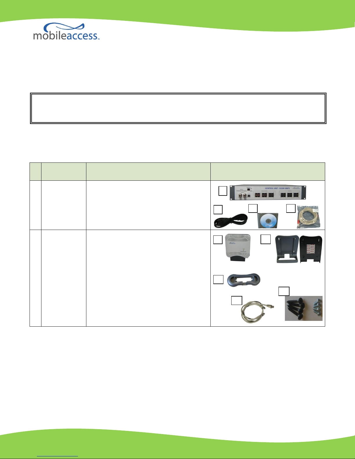
The MobileAccessVE Dual-Band Solution includes two kits: Control Unit Kit and Access Pod Kit.
Please verify that your kits include the items listed below.
Description
I VE Control
Unit (VCU) Kit
Kit Includes
A) VE Control Unit (includes brackets for
securing the VCU to 19” rack)
B) Power Cord*
C) VE SW CD
D) Local Configuration Cable (crossed RJ-45
cable)
Unit
NOTE: Only main items are displayed.
A
II VE Access
Pods (VAP) Kit
* The included power cord should not be used with any products other than the VE Control Unit.
A) VE Access Pod (VAP)
B) Wall Mount Adaptor (includes double-sided
sticky tape on rear for faster installation)
C) Desk Mount Adaptor
D) RJ-45 Cat-5e Jumper Cable
E) 8 Screws:
4 short screws – for securing the
adaptor to the Access Pod
4 long screws - for securing the wall
mount adaptor to the wall (for “antitheft” installation)
D
Front
E
Required Equipment (Not Included)
The following elements are provided by your wireless service provider and are NOT included in either kit:
Service Provider’s RF source - Macro BTS, Microcell, Picocell or Bi-Directional Amplifier (BDA)
Patch panel and jumper cables - typically included in your IDF/Telco closet
Rear
QIS_VE Dual Band_Rev A00 709C005002_28JAN10.doc 1
General Installation Approach
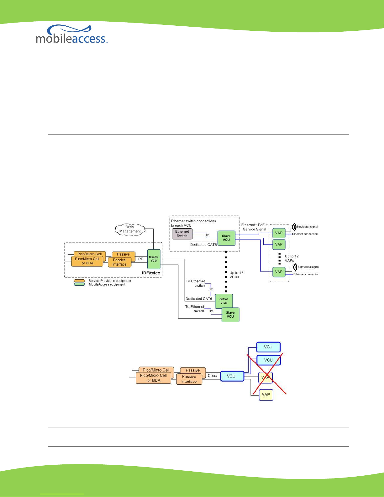
The VE Control Unit (VCU) can operate in ONE of the following modes where the operation mode is
automatically set by the unit according to the detected connections:
Master VE Control Unit (Master VCU) - connected to the RF source(s) and up to 12 VCUs.
Slave VE Control Unit (VCU) - Connected to the Master VCU and up to 12 VAPs.
NOTE: Do not connect VAPs and VCUs to the same VCU.
Service provider’s equipment (BTS, Repeater, etc.) is connected to the Master VCU through passive
interface (supplied by the service provider). The passive interface can either be a coaxial cable or include
other RF components such as splitters, attenuators, bi-directional couplers, etc.
Up to 12 Slave VCUs are connected to the Master VCU via dedicated CAT-6 cables.
Each Slave VCU is connected to an Ethernet switch (up to 12 ports) and up to 12 VAPs.
All VCUs (and their VAPs) are managed through the Master VCU WEB Management connection.
Figure 1: MobileAccessVE Dual-Band Basic Architecture
Figure 2: INCORRECT Installation – VAPs and VCUs connected to the Master VCU
NOTE: In installations of up to 12 VAPs, Slave VCUs are not required. VAPs can be connected directly to
the Master VCU.
QIS_VE Dual Band_Rev A00 709C005002_28JAN10.doc 2

Operations performed by the Wireless Service Provider
The wireless service provider is normally responsible for the following operations:
Installing the corresponding RF sources in the building; typically a Picocell, Microcell or Bi-Directional
Amplifier.
Connecting the RF sources to the relevant VE Control Unit through passive interface.
Providing the RF parameters for each service: DL Central Frequency, Maximum BTS Power Out (0dBm-
33dBm) and UL Gain (5dB to -15dB).
Infrastructure requirements:
1. IDF/Telco closet space for one or more VCUs, depending on the number and locations of the installed VCUs:
(48.3 x 51.3 x 8.88 cm) per VCU.
2. 350 Watts of AC power to the VCU IDF/Telco closet.
3. Building infrastructure:
a. Category-5e or Cat-6 cabling, Unshielded or Shielded Twisted Pair (UTP/STP).
b. 24 AWG minimum diameter for CAT-5e cabling.
c. Dedicated CAT-6/7 STP cable from Master VCU to Slave VCUs with run lengths NOT exceeding
100m (300ft) and not shorter than 10m (30ft).
d. CAT-5/6 UTP or STP cable from VCU to each VAP with run lengths NOT exceeding 100m (300ft)
and not shorter than 10m (30ft). VAPs can be connected over existing Cat-5e/6 cabling
infrastructure and existing Ethernet jacks without affecting the LAN.
Note: Verify with the IT department that existing cables support the VE installation. If infrastructure
documentation is available, review the documentation to determine cable types and lengths. If the cable
information is not available, attempt to visually identify the cable type (depending on the cable vendor,
the cable type may be listed on the cable sheath). It is recommended to use a Fluke cable tester to
measure the cable length of the most remote VAPs.
4. Master VCU Cable Connections:
a. 2 x N-type female, 50 ohm interfaces to carrier equipment
b. 12 x RJ-45 interfaces to Slave VCUs
c. 1 x RJ-45 interface to Management
d. 1 x D-Type 9 pins RS-232 interface for local craft
e. 1 x D-Type 15 pins interface for External Alarms (dry contacts)
5. Slave VCU Cable Connections
a. 1 x RJ-45 interface to Master VCU (not used in small single-tier deployments)
b. 12 x RJ-45 interfaces to VAPs
c. 12 x RJ-45 interfaces to Ethernet Switch for LAN service
d. 1 x D-Type 9 pins RS-232 interface for local craft
Note: Ethernet standards specify that the maximum distance between an Ethernet switch and appliance
(computer, WLAN AP etc) should not exceed 100m (300ft). Therefore, when MobileAccessVE shares the IT
LAN, the maximum distance for a given cable run between the Ethernet switch and appliance cannot be longer
than 100m (300ft), including all patch cords (from switch to VCU, from VCU to patch panel, from RJ-45 outlet
to VAP, and from VAP to appliance).
QIS_VE Dual Band_Rev A00 709C005002_28JAN10.doc 3
 Loading...