

MobileAccess MA 850 Installation Manual

Installation and Configuration Guide
M
M
M
o
o
o
b
b
b
i
l
e
A
c
c
e
s
s
8
5
0
(
f
o
r
F
C
C
)
i
l
e
A
c
c
e
s
s
8
5
0
(
f
o
r
F
i
l
e
A
c
c
e
s
s
8
5
0
(
f
o
r
F
C
C
C
C
)
)
P/N: 709C001103
REV: A00
Date: 06-NOV-06

Preface
Preface Material
MobileAccess Ltd. Vienna, Virginia Tel: +1-703-848-0200
http://www.MobileAccess.com
MA 850 Installation and Configuration Guide II

Preface
Preface Material
PPrreeffaaccee MMaatteerriiaall
© COPYRIGHT 2006, MOBILEACCESS NETWORKS INC. ALL RIGHTS RESERVED.
MOBILEACCESSTM IS A REGISTERED TRADEMARK OF MOBILEACCESS. THIS DOCUMENT CONTAINS OTHER TRADEMARKS, TRADE NAMES AND
SERVICE MARKS OF MOBILEACCESS AND OTHER ORGANIZATIONS, ALL OF W HICH ARE THE PROPERTY OF THEIR RESPECTIVE OWNERS.
THIS DOCUMENT CONTAINS CONFIDENTIAL AND PROPRIETARY INFORMATION OF MOBILEACCESS AND MAY NOT BE COPIED, TRANSMITTED, STORED
IN A RETRIEVAL SYSTEM OR REPRODUCED IN ANY FORMAT OR MEDIA, IN WHOLE OR IN PART, WITHOUT THE PRIOR WRITTEN CONSENT OF
MOBILEACCESS. INFORMATION CONTAINED IN THIS DOCUMENT SUPERSEDES ANY PREVIOUS MANUALS, GUIDES, SPECIFICATIONS, DATA SHEETS OR
OTHER INFORMATION THAT MAY HAVE BEEN PROVIDED OR MADE AVAILABLE TO THE USER.
THIS DOCUMENT IS PROVIDED FOR INFORMATIONAL PURPOSES ONLY, AND MOBILEACCESS DOES NOT WARRANT OR GUARANTEE THE ACCURACY,
ADEQUACY, QUALITY, VALIDITY, COMPLETENESS OR SUITABILITY FOR ANY PURPOSE OF THE INFORMATION CONTAINED IN THIS DOCUMENT.
MOBILEACCESS RESERVES THE RIGHT TO MAKE UPDATES, IMPROVEMENTS AND ENHANCEMENTS TO THIS DOCUMENT AND THE PRODUCTS TO
WHICH IT RELATES AT ANY TIME WITHOUT PRIOR NOTICE TO THE USER. MOBILEACCESS MAKES NO WARRANTIES, EXPRESS OR
IMPLIED, INCLUDING, WITHOUT LIMITATION, THOSE OF MERCHANTABILITY AND FITNESS FOR A PARTICULAR PURPOSE,
WITH RESPECT TO THIS DOCUMENT OR ANY INFORMATION CONTAINED HEREIN.
MA 850 Installation and Configuration Guide III

Preface
Preface Material
Policy for Warrantee and Repair
MOBILEACCESS TESTS AND INSPECTS ALL ITS PRODUCTS TO VERIFY THEIR QUALITY AND RELIABILITY. MOBILEACCESS USES EVERY REASONABLE
PRECAUTION TO ENSURE THAT EACH UNIT MEETS THEIR DECLARED SPECIFICATIONS BEFORE SHIPMENT. CUSTOMERS SHOULD ADVISE THEIR
INCOMING INSPECTION, ASSEMBLY, AND TEST PERSONNEL ABOUT THE PRECAUTIONS REQUIRED IN HANDLING AND TESTING OUR PRODUCTS. MANY
OF THESE PRECAUTIONS CAN BE FOUND IN THIS MANUAL.
THE PRODUCTS ARE COVERED BY THE FOLLOWING WARRANTIES:
General Warranty
MOBILEACCESS WARRANTS TO THE ORIGINAL PURCHASER ALL STANDARD PRODUCTS SOLD BY MOBILEACCESS TO BE FREE OF DEFECTS IN
MATERIAL AND WORKMANSHIP FOR ONE (1) YEAR FROM DATE OF SHIPMENT FROM MOBILEACCESS. DURING THE WARRANTY PERIOD,
MOBILEACCESS WILL REPAIR OR REPLACE ANY PRODUCT THAT MOBILEACCESS PROVES TO BE DEFECTIVE. THIS WARRANTY DOES NOT APPLY TO
ANY PRODUCT THAT HAS BEEN SUBJECT TO ALTERATION, ABUSE, IMPROPER INSTALLATION OR APPLICATION, ACCIDENT, ELECTRICAL OR
ENVIRONMENTAL OVER-STRESS, NEGLIGENCE IN USE, STORAGE, TRANSPORTATION OR HANDLING.
Specific Product Warranty Instructions
ALL MOBILEACCESS PRODUCTS ARE WARRANTED AGAINST DEFECTS IN WORKMANSHIP, MATERIALS AND CONSTRUCTION, AND TO NO FURTHER
EXTENT. ANY CLAIM FOR REPAIR OR REPLACEMENT OF UNITS FOUND TO BE DEFECTIVE ON INCOMING INSPECTION BY A CUSTOMER MUST BE MADE
WITHIN 30 DAYS OF RECEIPT OF SHIPMENT, OR WITHIN 30 DAYS OF DISCOVERY OF A DEFECT WITHIN THE WARRANTY PERIOD.
THIS WARRANTY IS THE ONLY WARRANTY MADE BY MOBILEACCESS AND IS IN LIEU OF ALL OTHER WARRANTIES, EXPRESSED OR IMPLIED.
MOBILEACCESS SALES AGENTS OR REPRESENTATIVES ARE NOT AUTHORIZED TO MAKE COMMITMENTS ON WARRANTY RETURNS.
Returns
IN THE EVENT THAT IT IS NECESSARY TO RETURN ANY PRODUCT AGAINST ABOVE WARRANTY, THE FOLLOWING PROCEDURE SHALL BE FOLLOW ED:
1. RETURN AUTHORIZATION IS TO BE RECEIVED FROM MOBILEACCESS PRIOR TO RETURNING ANY UNIT. ADVISE MOBILEACCESS OF THE MODEL,
SERIAL NUMBER, AND DISCREPANCY. THE UNIT MAY THEN BE FORWARDED TO MOBILEACCESS, TRANSPORTATION PREPAID. DEVICES RETURNED
COLLECT OR WITHOUT AUTHORIZATION MAY NOT BE ACCEPTED.
2. PRIOR TO REPAIR, MOBILEACCESS WILL ADVISE THE CUSTOMER OF OUR TEST RESULTS AND ANY CHARGES FOR REPAIRING CUSTOMER-CAUSED
PROBLEMS OR OUT-OF-WARRANTY CONDITIONS ETC.
3. REPAIRED PRODUCTS ARE WARRANTED FOR THE BALANCE OF THE ORIGINAL W ARRANTY PERIOD, OR AT LEAST 90 DAYS FROM DATE OF
SHIPMENT.
Limitations of Liabilities
MOBILEACCESS'S LIABILITY ON ANY CLAIM, OF ANY KIND, INCLUDING NEGLIGENCE FOR ANY LOSS OR DAMAGE ARISING FROM, CONNECTED WITH,
OR RESULTING FROM THE PURCHASE ORDER, CONTRACT, QUOTATION, OR FROM THE PERFORMANCE OR BREACH THEREOF, OR FROM THE DESIGN,
MANUFACTURE, SALE, DELIVERY, INSTALLATION, INSPECTION, OPERATION OR USE OF ANY EQUIPMENT COVERED BY OR FURNISHED UNDER THIS
CONTACT, SHALL IN NO CASE EXCEED THE PURCHASE PRICE OF THE DEVICE WHICH GIVES RISE TO THE CLAIM.
EXCEPT AS EXPRESSLY PROVIDED HEREIN, MOBILEACCESS MAKES NO WARRANTY, EXPRESSED OR IMPLIED, WITH
RESPECT TO ANY GOODS, PARTS AND SERVICES PROVIDED IN CONNECTION WITH THIS AGREEMENT INCLUDING, BUT NOT
LIMITED TO, THE IMPLIED WARRANTIES OF MERCHANTABILITY AND FITNESS FOR A PARTICULAR PURPOSE. MOBILEACCESS
SHALL NOT BE LIABLE FOR ANY OTHER DAMAGE INCLUDING, BUT NOT LIMITED TO, INDIRECT, SPECIAL OR CONSEQUENTIAL
DAMAGES ARISING OUT OF OR IN CONNECTION WITH FURNISHING OF GOODS, PARTS AND SERVICE HEREUNDER, OR THE
PERFORMANCE, USE OF, OR INABILITY TO USE THE GOODS, PARTS AND SERVICE.
MA 850 Installation and Configuration Guide IV
Preface
Preface Material
Reporting Defects
THE UNITS WERE INSPECTED BEFORE SHIPMENT AND FOUND TO BE FREE OF MECHANICAL AND ELECTRICAL DEFECTS.
EXAMINE THE UNITS FOR ANY DAMAGE THAT MAY HAVE BEEN CAUSED IN TRANSIT. IF DAMAGE IS DISCOVERED, FILE A CLAIM WITH THE FREIGHT
CARRIER IMMEDIATELY. NOTIFY MOBILEACCESS AS SOON AS POSSIBLE.
NOTE: KEEP ALL PACKING MATERIAL UNTIL YOU HAVE COMPLETED THE INSPECTION
WARNING: TO COMPLY WITH FCC RF EXPOSURE COMPLIANCE REQUIREMENTS, ANTENNAS USED FOR THIS PRODUCT MUST BE FIXED MOUNTED
ON INDOOR PERMANENT STRUCTURES, PROVIDING A SEPARATION DISTANCE OF AT LEAST 20 CM FROM ALL PERSONS DURING NORMAL OPERATION.
WARNING: ANTENNA GAIN SHOULD NOT EXCEED 10 dBi.
WARNING: EACH INDIVIDUAL ANTENNA USED FOR THIS TRANSMITTER MUST BE INSTALLED TO PROVIDE A MINIMUM SEPARATION DISTANCE OF 20
CM OR MORE FROM ALL PERSONS AND MUST NOT BE CO-LOCATED WITH ANY OTHER ANTENNA FOR MEETING RF EXPOSURE REQUIREMENTS.
WARNING: THE DESIGN OF THE ANTENNA INSTALLATION NEEDS TO BE IMPLEMENTED IN SUCH A WAY SO AS TO ENSURE RF RADIATION SAFETY
LEVELS AND NON-ENVIRONMENTAL POLLUTION DURING OPERATION.
ATTENTION:
COMPLIANCE WITH RF SAFETY REQUIREMENTS:
MOBILEACCESS™ PRODUCTS HAVE NO INHERENT SIGNIFICANT RF RADIATION.
THE RF LEVEL ON THE DOWN LINK IS VERY LOW AT THE DOWNLINK PORTS. THEREFORE, THERE IS NO DANGEROUS RF RADIATION WHEN THE
ANTENNA IS NOT CONNECTED.
Safety
WARNING! To comply with FCC RF exposure compliance requirements, antennas used for this product
must be fixed mounted on indoor permanent structures, providing a separation distance of at least
20 cm from all persons during normal operation.
1. Each individual antenna used for this transmitter must be installed to
provide a minimum separation distance of 20 cm or more from all persons
and must not be co-located with any other antenna for meeting RF
exposure requirements.
2. The design of the antenna installation needs to be implemented in such a
way so as to ensure RF radiation safety levels and non-environmental
pollution during operation.
Compliance with RF safety requirements:
• MobileAccess™ products have no inherent significant RF radiation.
• The RF level on the downlink is very low at the downlink ports. Therefore, there is no
dangerous RF radiation when the antenna is not connected.
MA 850 Installation and Configuration Guide V

Preface
Preface Material
Certification
MobileAccess products have met the approvals of the following certifying organizations:
ISO 9001:2000 (from March 15, 2004)
FCC Certification
For US: FCC 47 CFT part 15 for 802.11b/g
Per section 15.204B.
ID:OJFMA850 will only be supplied as complete system per section 15.204(b) of rules.
FCC certification for MA 850 is valid for use only with the following elements:
Antenna types: section 2.4.1 in this User Guide
AP Types: section 2.5 in the User Guide
NOTE: This equipment has been tested and found to comply with the limits for a Class B digital
device, pursuant to Part 15 of the FCC Rules. These limits are designed to provide reasonable
protection against harmful interference in a residential installation. This equipment generates,
uses and can radiate radio frequency energy and, if not installed and used in accordance with
the instructions, may cause harmful interference to radio communications. However, there is no
guarantee that interference will not occur in a particular installation. If this equipment does
cause harmful interference to radio or television reception, which can be determined by turning
the equipment off and on, the user is encouraged to try to correct the interference by one or
more of the following measures:
• Reorient or relocate the receiving antenna.
• Increase the separation between the equipment and receiver.
• Connect the equipment into an outlet on a circuit different from that to which the receiver is
connected.
• Consult the dealer or an experienced radio/TV technician for help.
WARNING! Changes or modifications to this equipment not expressly approved by the party responsible
for compliance MobileAccess Ltd. could void the user’s authority to operate the equipment.
MA 850 Installation and Configuration Guide VI

Preface
Preface Material
Professional Installation of Transmitter
According to FCC 15.203, if an intentional radiator has a standard antenna connector, it must be
professionally installed according to FCC 15.203 regulations:
1. The MA850 cannot be sold to the general public. Only professional installer, qualified ("licensed") by
MobileAccess for this purpose is aloud to install the MA850.
2. The installation must be controlled and follow the requirement of "Installation Manual"
(P/N:709C001103). Each potential installer must receive special training, which is a condition for
receiving the license from MobileAccess Inc to become a "licensed" installer. The installation
procedure as described in the "Installation Manual" includes the mechanical installation and initial
setup by a PC based tool.
3. The intended application of the system is exclusively for the commercial/industry use.
MA 850 Installation and Configuration Guide VII

Preface
Preface Material
About This Guide
This user guide provides all the information necessary to install and configure the MobileAccess
MA 850.
Revision History
The revision history for this document is shown in Table 1-1.
Table 1-1: Revision history
P/N and REV Date Description
MA 850 Installation and Configuration Guide VIII

Preface
Preface Material
List of Acronyms
AGC Automatic Gain Control
BDA Bi-Directional Amplifier
BU Base Unit
DL Downlink
RHU Remote Hub Unit
SNR Signal to Noise Ratio
UL Uplink
VDC Volts Direct Current
AP Access Point
MA 850 Installation and Configuration Guide IX

Preface
Preface Material
Table of Contents
Preface Material .......................................................................................................................III
Policy for Warrantee and Repair......................................................................................................... IV
Certification ...................................................................................................................................... VI
Professional Installation of Transmitter..............................................................................................VII
About This Guide ............................................................................................................................VIII
Revision History ..............................................................................................................................VIII
List of Acronyms ............................................................................................................................... IX
Table of Contents................................................................................................................................X
Introduction to the MA 850 System ........................................................................................1
1.1 About MobileAccess MA 850 .........................................................................................................1
1.1.1 MA 850 Features and Capabilities ........................................................................................2
1.2 MA 850 Front and Rear Panels......................................................................................................3
1.2.1 Front Panel Connections and LEDs.......................................................................................3
1.2.2 Rear Panel Port Connections and LEDs ................................................................................4
1.3 Unit Architecture..........................................................................................................................5
1.4 Installation Configurations ............................................................................................................5
1.4.1 Standalone.........................................................................................................................6
1.4.2 Add-On to MA 1000 RHU ....................................................................................................6
1.4.3 Add-on to MA 2000 System .................................................................................................7
1.5 Signal Distribution in the MA 850 ..................................................................................................8
1.6 Commissioning and Monitoring .....................................................................................................8
Infrastructure Preparation.......................................................................................................9
2.1 Installation Requirements.............................................................................................................9
2.2 Coaxial Cable Connections ..........................................................................................................10
2.2.1 General Cable Installation Procedures ................................................................................10
2.2.2 RF Rules ..........................................................................................................................10
2.3 Power Consumption, Connections and Power Supplies .................................................................11
2.3.1 Power Safety Instructions .................................................................................................11
2.3.2 MA 850 Power Consumption..............................................................................................11
2.3.3 Types of Power Supplies ...................................................................................................11
MA 850 Installation and Configuration Guide X

Preface
Preface Material
2.3.4 Power Connections ...........................................................................................................11
2.4 In-building Antennas..................................................................................................................12
2.4.1 Antenna Types .................................................................................................................12
2.4.2 Antenna Connections ........................................................................................................12
2.5 Access Points .............................................................................................................................13
Installation..............................................................................................................................14
3.1 Accessory Kits............................................................................................................................14
3.2 Placing the Unit and Recording Location......................................................................................15
3.3 Standalone Wall Mount Installation .............................................................................................15
3.4 Add-on to an MA 1000 System Installation ..................................................................................16
3.5 Add-on to an MA 1000 with MA 1200 ..........................................................................................19
3.6 Add-on to an MA 2000 System....................................................................................................22
3.6.1 MA 850 RC 2000 Assembly................................................................................................22
3.6.2 MA 850 Rack Mount..........................................................................................................24
3.6.3 MA 850 Wall Mount Installation .........................................................................................24
Configuration and Management............................................................................................25
4.1 Local Configuration and Monitoring .............................................................................................26
4.1.1 Getting Started.................................................................................................................26
4.1.2 MA 850 Customer Tool Window Description .......................................................................27
4.1.3 Configuration Using MA 850 Customer Tool........................................................................28
4.1.4 Monitoring Using MA 850 Customer Tool............................................................................28
4.2 Remote - Web Browser Session ..................................................................................................29
4.2.1 IP Configuration Procedure ...............................................................................................30
4.2.1.1 Connecting to the Network ...................................................................................30
4.2.1.2 Performing Auto-Discovery....................................................................................30
4.2.1.3 Assigning a Static IP Address ................................................................................31
4.2.1.4 Configuring the SNMP Parameters .........................................................................34
4.2.1.5 Configuring Serial Parameters ...............................................................................36
4.2.2 Login and User Levels.......................................................................................................37
4.2.3 MA 850 View ....................................................................................................................38
4.3 Gain Setting ..............................................................................................................................39
4.4 Monitoring Alarms......................................................................................................................40
SNMP Management Using Any Standard SNMP Manager ..................................................41
5.1 Traps List ..................................................................................................................................41
MA 850 Installation and Configuration Guide XI

Preface
Preface Material
Specifications.........................................................................................................................43
MA 850 Installation and Configuration Guide XII

IInnttrroodduuccttiioonn ttoo tthhee MMAA 885500 SSyysstteemm
This chapter provides a description of the MA 850 system, its architecture, installation
configurations, operation and required commissioning procedures.
1.1 About MobileAccess MA 850
Figure 1-1. MobileAccess 850
1
The MA-850 Wi-Fi Module enables 802.11b/g Wi-Fi signals to be combined with other wireless
services for simultaneous distribution over the MobileAccess Universal Wireless Network. It can
be deployed in a stand-alone mode, for distribution of Wi-Fi only, or it can be connected to
other MobileAccess elements (MA-1000/2000) to deliver Wi-Fi along with other wireless services
including cellular/PCS, public safety, and WMTS.
Unlike traditional Wi-Fi deployments, where 802.11 Access Points (APs) are installed on ceilings
and walls throughout the facility, the MA-850 enables organizations to cluster their 802.11 APs
together in secure telecom closets. With the clustering approach, IT managers can more easily
access APs, which ultimately reduces the operational costs of managing the Wi-Fi network and
minimizes disruption within the facility.
MA 850 Installation and Configuration Guide 1

1.1.1 MA 850 Features and Capabilities
• Multi-use infrastructure:
The same cables and antennas used for Wi-Fi can be used to support the simultaneous
extension and distribution of other wireless voice and data services, as follows:
o Support for four 802.11b/g AP ports
o Mobile services from MobileAccess 1000/2000, ModuLite or Litenna remote units
• Simple installation and maintenance:
o All active elements are in the telecom shaft or closet
o All data and voice services distributed via a common coax cabling and broadband
antennas
o AP Clustering - 802.11 access points (APs) connect to the MA 850 in telecom closets
• Scalable: Additional APs connected as needed to the MA 850
• Management:
o Robust system management - Familiar SNMP-based management provides proactive
visibility and control of the MA 850 based Wi-Fi infrastructure.
o Management through local RS232 connection and remote WEB management
About MobileAccess MA 850
• WI-Fi applications transparency - The MA 850 uses discrete, passive antennas to
radiate 802.11 signals, providing a coverage architecture that replicates the behaviors
necessary to transparently support advanced AP features and location-sensitive Wi-Fi
applications.
• High-power - With integral constant gain amplifiers combined with its low-loss
architecture, the MA 850 offers scalable support for demanding applications such as wireless
VoIP
MA 850 Installation and Configuration Guide 2
1.2 MA 850 Front and Rear Panels
Mobile service connections
Antenna connections
Power
Local Setup
This section describes the MA 850 front- and rear-panel connections and LEDs.
1.2.1 Front Panel Connections and LEDs
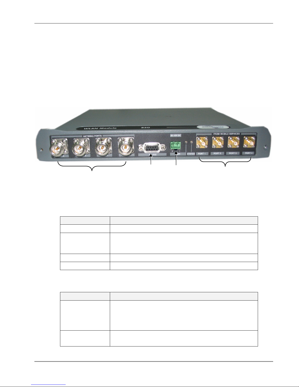
The front panel contains the antenna connections and mobile services connections, power and
local setup connections. The following figure shows the MA 850 front panel.
MA 850 Front and Rear Panels
Figure 1-2. MobileAccess 850 Front View
Front Panel Ports
The following table describes the front panel ports.
Front Panel Ports Description
Antenna Ports Four n-type female antenna connections
Mobile Services
Four SMA female connections used in installations that integrate
MA 850 with MA 1000 RHUs or MA 2000 services.
NOTE: To be terminated with 50 ohm terminations when not in use.
Local RS232 connection for local setup (see section 4.1).
DC Power connection: 20V to 48V (see 2.3.3)
Front Panel LEDs
The front panel contains two LEDs, described in the following table.
Front Panel LEDs Description
Run Internal operation and channel operation status:
o Green blinking – unit OK
o Off – fault detected in unit
o Red blinking – failure of one of the channels
PWR (Unlabeled LED adjacent to the power connection).
Green – Power OK.
MA 850 Installation and Configuration Guide 3
1.2.2 Rear Panel Port Connections and LEDs
Antenna sense
connection
802.11b/g AP connectio
ns
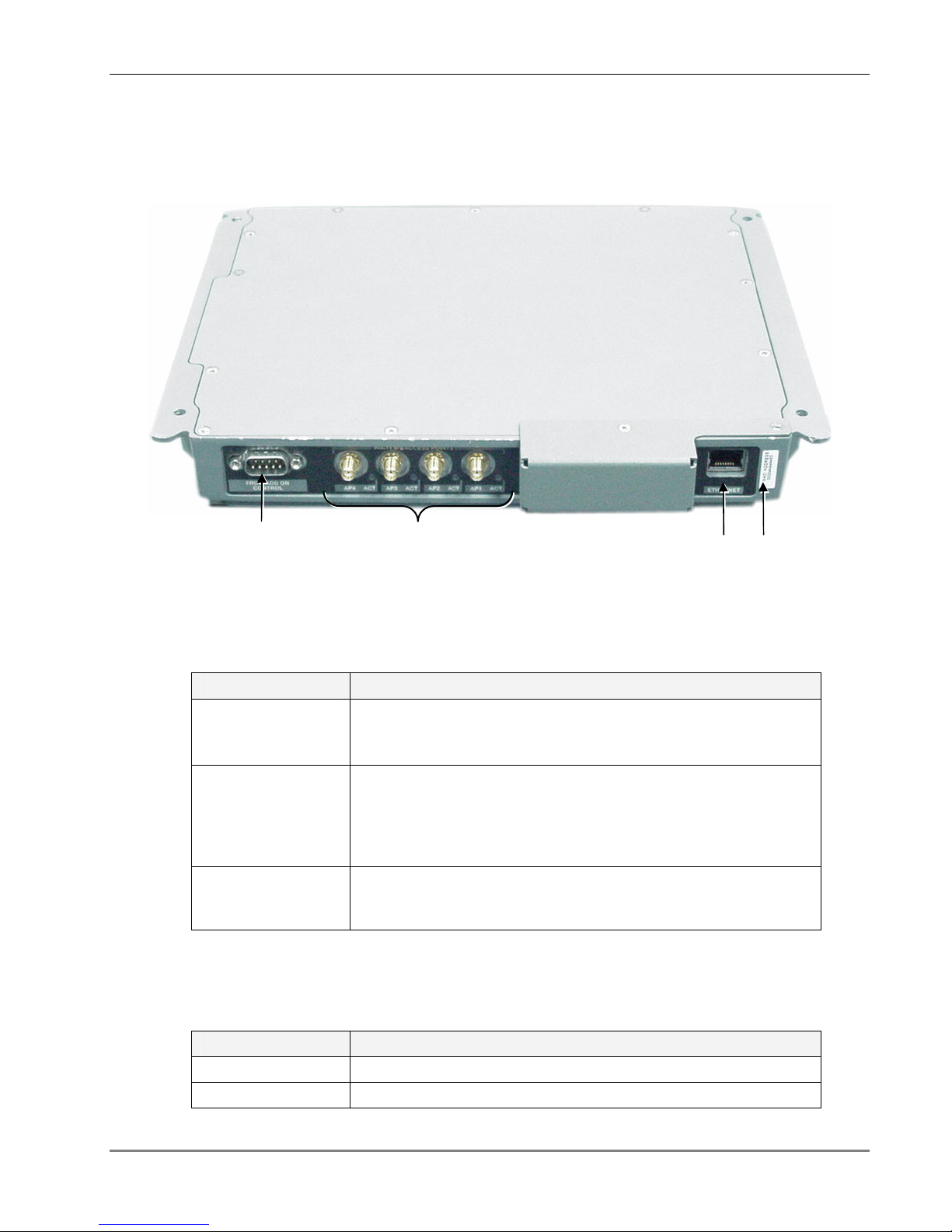
The rear panel contains the 802.11b/g AP connections, Ethernet connection for remote
management and antenna sensing connector.
MA 850 Front and Rear Panels
Figure 1-3. MobileAccess 850 Rear View
Rear Panel Ports
The following table describes the rear panel ports.
Rear Panel Ports Description
802.11b/g APs
Four 802.11b/g connections. (See LED descriptions in the
following table).
NOTE: To be terminated with 50 ohm terminations when not in use.
Connection to
control
Relevant only when installed as part of a MA 1000 system.
Connects to RHU 1000 rear panel Control connector. Routes the
antenna sensing (indication of whether antenna is present) to the
RHU for monitoring via the management application. (RHU
Version 3.1 and higher).
Ethernet port
Connection to network for configuration and management
through a WEB browser.
near the port.
The default IP Address is on the label
Rear Panel 802.11 b/g AP LEDs
Ethernet
port
MAC
Address
The rear panel LEDs indicate connection point of corresponding 802.11b/g AP.
Rear Panel LEDs Description
Blinking green AP connected and working.
Red Corresponding AP is not connected or does not transmit.
MA 850 Installation and Configuration Guide 4

1.3 Unit Architecture
Unit Architecture
MA 850 consists of the following main
• Interface: Provides interface to the 802.11b/g AP ports.
• Gain control mechanism: Gain control to adjust 802.11b/g signals to specific site
• Combining and separating mechanism: On the downlink, combines the amplified
802.11b/g signals with the 802.11a AP signals and those of mobile services. On the
uplink, separates the signals and routes them to the corresponding ports.
• Monitoring and control: Support for WEB monitoring, SNMP MIBs displayed via a
standard Web browser and local RS232 and service options.
Figure 1-4. MobileAccess 850 Functional Block Diagram
functional
modules:
1.4 Installation Configurations
MA 850 can be installed in the following configurations:
• Standalone – to provide coverage for 802.11b/g services only
• Add-on to a MobileAccess 1000 series RHU (with and without MA 1200 add-on)
• Add-on to MobileAccess 2000 system
NOTE: In all installation types, all the signals are converged via the MA 850 and distributed via
the antennas connected to the MA 850 antenna ports.
MA 850 Installation and Configuration Guide 5
 Loading...