

Page 1

UM-1000, Revision 2.2 I
MobileAccess™
MobileAccess™MobileAccess™
MobileAccess™ 1000/1200
Installation and Configuration Guide
UM-1000, Revision 2.2
December 09, 2003
Page 2

Introduction MobileAccess™ 1000/1200
II UM-1000, Revision 2.2
Copyright © 2003 MobileAccess.
All rights reserved. Printed in Israel.
© 2003 by MobileAccess
This document contains confidential and proprietary information of MobileAccess
and may not be copied, transmitted, stored in a retrieval system or reproduced in
any format or media, in whole or in part, without the prior written consent of
MobileAccess. Information contained in this document supersedes any previous
manuals, guides, specifications, data sheets or other information that may have
been provided or made available to the user. This document is provided for
informational purposes only, and MobileAccess does not warrant or guarantee the
accuracy, adequacy, quality, validity, completeness or suitability f or any purpose of
the information cont ained in this document. MobileAccess reserves the right to make
updates, improvements and enhancements to this document and the products to
which it relates at any time without prior notice to the user. MOBILEACCESS
MAKES NO WARRANTIES, EXPRESS OR IMPLIED, INCLUDING, WITHOUT
LIMITATION, THOSE OF MERCHANTABILITY AND FITNESS FOR A
PARTICULAR PURPOSE, WITH RESPECT TO THIS DOCUMENT OR ANY
INFORMATION CONTAI NED HEREIN.
TRADEMA RK A CKNOWLEDGEMENT
MobileAccess
TM
is a registered trademarks of MobileAccess. This document contains
other trademarks, trade names and service marks of MobileAccess and other
organizations, all of which are the property of their respective owners.
MobileAccess Ltd. Vienna, Virginia Tel: +1-703-848-0200
MobileAccess Ltd. Lod, Israel Tel: +972-8-9183888
http://www.mobileaccess.com
Email: [email protected]
Page 3

MobileAccess™ 1000/1200 Introduction
UM-1000, Revision 2.2 III
POLICY FOR WARRANTEE AND REPAIR
MobileAccess tests and inspects all its products to verify their quality and reliability.
MobileAccess uses every reasonable precaution to ensure that each unit meets their
declared specifications bef ore shipment. Custom ers should advise their incoming inspection,
assembly, and test personnel about the precautions required in handling and testing our
products. Many of these precautions can be found in this manual.
The products are covered by the following warranties:
General Warranty
MobileAccess warrants to the original purchas er all standard products sold by MobileAccess
to be free of defects in material and workmanship for one (1) year from date of shipment fr om
MobileAccess. During the warranty period, MobileAccess will repair or replace any product
that MobileAccess proves to be defective. T his warranty does not apply to any product that
has been subject to alteration, abuse, im proper installation or application, accident, elec trical
or environmental over-stress, negligence in use, storage, transportation or handling.
Specific Product Warranty Instructions
All MobileAccess products are warranted against defects in workmanship, materials and
construction, and to no f ur ther extent. Any claim f or r epair or replac ement of units found to be
defective on incoming inspection by a custom er must be made within 30 days of receipt of
shipment, or within 30 days of discovery of a defect within the warranty period.
This warranty is the only warranty made by MobileAccess and is in lieu of all other
warranties, expressed or implied. MobileAccess sales agents or representatives are not
authorized to make commitments on warranty returns.
RETURNS
In the event that it is necessary to return any product against above warranty, the
following procedure shall be followed:
1. Return authorization is to be received from MobileAccess prior t o r eturning any
unit. Advise MobileAccess of the model, serial number, and discrepancy. The
unit may then be forwarded to MobileAccess, transportation prepaid. Devices
returned collect or without authorization may not be accepted.
2. Prior to repair, MobileAccess will advise the customer of our test results and any
charges for repairing customer-caused problems or out-of-warranty conditions
etc.
3. Repaired products are warranted for t he balance of the original warranty period,
or at least 90 days from date of shipm ent.
Page 4

Introduction MobileAccess™ 1000/1200
IV UM-1000, Revision 2.2
LIMITATIONS OF LIABILITIES
MobileAccess's liability on any claim, of any kind, including negligence for any loss or
damage arising from, connected with, or resulting from the purchase order, contract,
quotation, or from the perform ance or breach ther eof, or from the design, m anufacture, sale,
delivery, installation, inspection, operation or use of any equipment covered by or furnished
under this contact, shall in no case exc eed the purchase price of the device which gives rise
to the claim.
EXCEPT AS EXPRESSLY PROVIDED HEREIN, MOBILEACCESS MAKES NO WARRANTY, EXPRESSED OR
IMPLIED, W ITH RESP ECT TO A NY GOODS, P ARTS AND S ERVI CES P ROVIDE D IN CONNECTION WITH THIS
AGREEMENT INCLUDING, B UT NOT LIMITED TO, THE IMPLIED W ARRANTIES OF MERCHANT ABILITY AND
FITNESS FOR A PARTICULAR PURPOSE. MOBILEACCESS SHALL NOT BE LIABLE FOR ANY OTHER
DAMAGE INCLUDING, BUT NOT LIMITED TO, INDIRECT, SPECIAL OR CONSEQUENTIAL DAMAGES ARISING
OUT OF OR IN CONNECTION WITH FURNI SHING OF GOODS, PA RTS AND SERVICE HEREUNDE R, OR THE
PERFORMANCE, USE OF, OR INABILITY TO USE THE GOODS, PARTS AND SERVICE.
REPORTING DEFECTS
The units were inspected befor e shipment and found to be free of mechanical and electric al
defects.
Examine the units for any damage that may have been caused in transit. If damage is
discovered, file a claim with the fr eight carrier immediately. Notify MobileAccess as soon as
possible.
NOTE: Keep all packing material until you have completed the inspection
WARNING: To comply with FCC RF exposure com pliance requir em ents, antennas us ed for
this product must be fix ed mounted on indoor permanent structures, pr oviding a separation
distance of at least 20 cm from all persons during normal operation.
WARNING: Antenna gain should not exceed 10dB.
WARNING: Eac h individual antenna used for this transmitter m ust be installed to provide a
minimum separation dist ance of 20 cm or more f rom all per sons and mus t not be co-located
with any other antenna for meeting RF exposure requirements.
Page 5

MobileAccess™ 1000/1200 Introduction
UM-1000, Revision 2.2 V
WARNING: The MobileAccessTM system uses an optical laser for transmitting voice and
data. The laser unit has the following output characteristics:
- Optical output power (mW): ≤3.0
- Wavelength (nM): 1310 ± 10
WARNING: Applying power to the MobileAccess™ creates a laser energy source operating
in class I as defined by IEC 60825-1, 21 CFR 1040.10 and 1040.11 except for deviations
pursuant to laser notice no. 50 (July 26, 2001). Use either an infrar ed viewer, optical power
meter or fluorescent screen for optical output verification.
WARNING: The use of controls or adjustm ents or perf ormanc e procedures other than those
specified herein may result in hazardous radiation exposure.
WARNING:
Compliance with RF safety requirements:
MobileAccess™ products have no inherent significant RF radiation.
The RF level on the down link is very low at the remote hub unit downlink ports . Therefore,
there is no dangerous RF radiation when the antenna is not connected.
The design of the antenna installation needs to be implemented in such a way so as to
ensure RF radiation safety levels and non- environmental pollution during operation.
ATTENTION: To avoid damaging your product, please observe the following:
• Always keep the optical c onnector covered. Use the fiber optic cable or a protective
cover. Do not allow any dirt and/or foreign material to get on the optical connector
bulkheads.
• T he optical fiber jum per cable bend r adius is 3 cm . Sm aller radii can c ause exces sive
optical loss and/or fiber breakage.
• For proper system performance only use cables equipped with
SC/APC connectors to connect to the MobileAccess system.
Page 6

Introduction MobileAccess™ 1000/1200
VI UM-1000, Revision 2.2
C
ERTIFICATION
MobileAccess products have met the approvals of the following certifying organizations:
ISO 9001
For US
FCC 47 CFT part 22,24,90
FDA-CDRH
For Canada
RSS-118, RSS-119, RSS-133
….
SPECIFICATIONS
Maximum ambient operating temperature: 50° C
Maximum ambient temperature in a rack: 50° C
Page 7

MobileAccess™ 1000/1200 Introduction
UM-1000, Revision 2.2 VII
Preface
This user guide provides all the information necessary to install and configure the
MobileAccess 1000/1200 system.
Revision History
The revision history for this document is shown in Table 1-1.
Table 1-1: Revision history
Version Date Description
1.0 April 2003 Initial version.
2.0 October 2003 Updated version to MobileAccess.
2.1 November 2003 Review and editing
2.2 December 2003 Adding and updating RHU 1200
Page 8

UM-1000, Revision 2.2 VIII
Table of Contents
Chapter 1. Introduction...............................................................................................................................................1
1.1 About MobileAccess 1000/1200™.........................................................................................................................1
1.2 System Description................................................................................................................................................2
1.3 Base Unit to Remote Unit Configuration Options...................................................................................................4
1.4 MobileAccess Models............................................................................................................................................5
Chapter 2. Infrastructure Preparation .......................................................................................................................8
2.1 Basic Installation Rules..........................................................................................................................................8
2.1.1 Fiber Optic Rules........................................................................................................................................8
2.1.2 RF Rules.....................................................................................................................................................8
2.2 Power Consumption, Connections and Power Supplies........................................................................................9
2.2.1 Power Consumption of Units......................................................................................................................9
2.2.2 Power Supply Configurations.....................................................................................................................9
2.2.3 Types of Power Supplies..........................................................................................................................10
2.3 Single-building Installation...................................................................................................................................11
2.4 Horizontal Layout Installation...............................................................................................................................13
Chapter 3. Connections............................................................................................................................................14
3.1 Rack Installation ..................................................................................................................................................14
3.2 Module Descriptions and Connections.................................................................................................................15
3.2.1 Radio Interface Unit (RIU)........................................................................................................................15
3.2.1.1 RIU Front Panel........................................................................................................................15
3.2.1.2 RIU Rear Panel.........................................................................................................................16
3.2.1.3 RIU Connections.......................................................................................................................16
3.2.1.4 Connections to Additional BUs..................................................................................................17
3.2.2 Base Units ................................................................................................................................................18
3.2.2.1 BU Front Panel.........................................................................................................................18
3.2.2.2 BU Rear Panel..........................................................................................................................19
3.2.2.3 Base Unit to RHU connections..................................................................................................19
3.2.3 Remote Hub Unit (RHU) 1000..................................................................................................................20
3.2.3.1 Wall Mount................................................................................................................................21
3.2.3.2 Connections..............................................................................................................................21
3.2.4 RHU 1200.................................................................................................................................................22
3.2.4.1 Assembly and Connections......................................................................................................23
3.2.5 MobileAccess 410/430 Controller.............................................................................................................25
3.2.5.1 Controller Front Panel...............................................................................................................25
3.2.5.2 Controller Rear Panel...............................................................................................................26
Chapter 4. Appendices.............................................................................................................................................27
4.1 Appendix I: Optical Test Procedure.....................................................................................................................27
4.1.1 Fiber Optic Cable Test..............................................................................................................................27
4.1.2 MobileAccess System Characteristics......................................................................................................27
4.1.3 Test Equipment ........................................................................................................................................28
Page 9

MobileAccess™ 1000/1200 Introduction
UM-1000, Revision 2.2 IX
4.1.4 Optical Insertion Loss Measurement Test................................................................................................28
4.1.4.1 Method #1: Two Point Test.......................................................................................................28
4.1.4.2 Method #2: Single Point Test....................................................................................................29
4.1.5 Other Test Equipment..............................................................................................................................29
4.1.6 Optical Return Loss Measurement Test...................................................................................................30
4.1.7 Measurement Procedure..........................................................................................................................30
4.1.7.1 Measuring Power Input To Cable Being Tested.......................................................................30
4.1.7.2 Measuring Coupler Power Loss................................................................................................30
4.1.7.3 Measuring Return Power..........................................................................................................30
4.1.8 Results.....................................................................................................................................................31
4.1.9 Summary..................................................................................................................................................31
4.2 Appendix II: Link Measurements Form................................................................................................................32
4.3 Frequently Asked Questions................................................................................................................................33
Page 10

Page 11

UM-1000, Revision 2.2 1
Chapter 1. Introduction
1.1 About MobileAccess 1000/1200™
MobileAccess™ 1000 family of products provides seamless coverage for voice and
data wireless services in difficult indoor environments where steel, concrete and
earth block RF signals, or in high- rise buildings where reception of multiple signals
causes interference.
The MobileAccess™ converged wireless networks solution is designed to serve
multiple wireless services through a single common cabling infrastructure.
Homogeneous coverage is pr ovided by antennas connected to Remote Hub Units
(RHUs) distributed throughout t he coverage area.
The MobileAccess™ infrastructure is protocol-independent and can simultaneously
serve various services. Built-in alarm and control capabilities that enable remote
monitoring and control of the system elem ent s (including antennas).
Features
• Single cabling and antenna system for all services and frequency bands
• Support for all current and future voice and data wireless services such as
PCS/CELLULAR, TDMA, CDMA, GSM, future 3G protocols, Paging, iDEN
and 802.11 (a,b,g) Wireless LAN
• Upgradeable to include additional services
• Eliminates RF interferences occurring where multiple antenna systems are
used to serve multiple services
• Enables fast deployment for corporate enterprises, property owners and
WSP’s of new services
• Reduces tenant disruption
• Low power required by the system eliminates the need for high power
BTS/RBS, reducing operator expenses
• Provides both local and remote monitoring and control capabilities
• Software programmable param et ers including output power, AGC (on/off and
levels), and system gain
• Real time component setting capabilities for optimal performance (aging,
temperature, optical connectors, et c. ,)
• Modular design architecture
Page 12

Introduction MobileAccess™ 1000/1200
2 UM-1000, Revision 2.2
1.2 System Description
The MobileAccess™ system provides in-building coverage by routing RF signals
from (up to three) BT S or BDA units, t hrough optic f ibers to remote areas where the
signals are converted back to RF and interfaced to antennas covering the remote
area. All system elements can be remotely controlled and monit ored from a single
location.
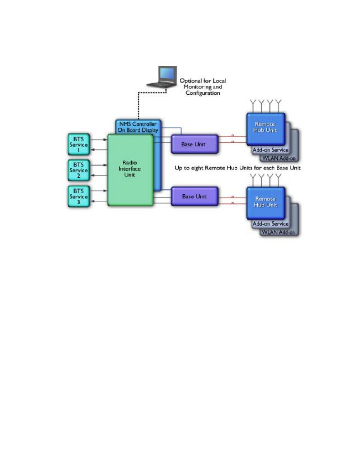
The MobileAccess™ coax and Fiber Optic hybrid solution consists of the following
elements:
• Radio Interface Unit (RIU) – Provides direct, sim ple interface to up to three
BTS or BDA units supporting up to three diff erent services. Connections can
be simplex or duplex.
RIU output signal is automatically adjusted to respond to a range of BTS or BDA
output power levels. This significantly reduces or elim inat es the need for
extensive manual site measurements and adjustments required to provide the
optimal input to the Base Units.
The RIU RF output signals are combined and fed via direct coax connection to
MobileAccess Base Units.
• Base Units (BUs) – convert the RF signal received f rom the RIU (or passive
interface) to an optic signal that is then split and routed via optic fiber to
Remote Hub Units located in remot e locations. Each BU can support up to
eight RHUs.
• Remote Hub Units (RHUs) – converts the optic sig nal to an RF signal and
feeds it to the antennas in the rem ote areas in order to provide the required
coverage. Each RHU supports two differ ent services (one high-band and one
low-band) and provides coax connections to up to four antennas. The RHU
filters and amplifies the optic signal received from the BU according to the
service it supports.
A third service can be added using a MobileAccess 1200 add-on or independent
module.
Wireless LAN services can also be added to the MobileAccess 1000 RHU by
connecting the MobileAccess 840 add-on module. This provides wireless LAN
signals to the antennas connected to the MobileAccess 1000 RHU.
• System Controller – provides monitoring and control to all MobileAccess
system elements, from a single locat ion.
Page 13
MobileAccess™ 1000/1200 Introduction
UM-1000, Revision 2.2 3
A block diagram of the MobileAccess™ system is given below.
Figure 1-1. MobileAccess™ System Block Diagram
The Base Units and controller (along with the power supplies and other elements
required for interf ace) are usually installed in the same rack in the communication
room, while the RHUs are distributed throughout the locations to be covered. In the
communication room located next t o the BT S or BDA, the RI U is also installed in t he
rack.
Page 14
Introduction MobileAccess™ 1000/1200
4 UM-1000, Revision 2.2
1.3 Base Unit to Remote Unit Configuration
Options
The MobileAccess™ 1000/1200 system includes three basic configuration options:
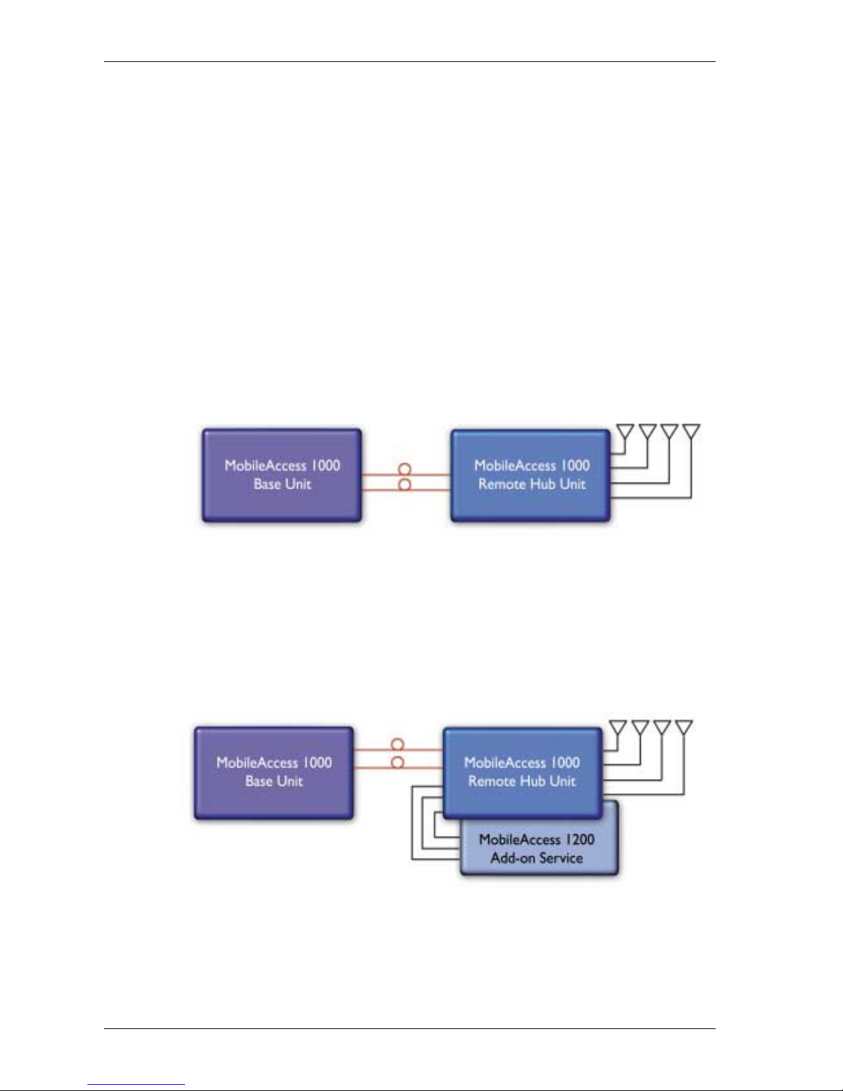
A) Basic configuration
In the basic configuration, depicted below, the Base Unit drives a single or dual
band, MobileAccess™ 1000 RHU. The dual band RHU consists of a low band
service (cellular 800, iDEN, Paging, or GSM 900) and a high band service (PCS
1900 or DCS 1800).
Figure 1-2. MobileAccess 1000 Basic BU – RHU Configuration
B) Using the MobileAccess 1200 add-on unit to provide an additional
service
In the second option, a MobileAccess™ 1200 add-on unit can be added in order to
provide an additional service. The add-on unit can be Cellular, PCS, UMTS, 3G, or
any future service.
Figure 1-3. MobileAccess 1000/1200 BU – RHU Plus Add-On
Page 15
MobileAccess™ 1000/1200 Introduction
UM-1000, Revision 2.2 5
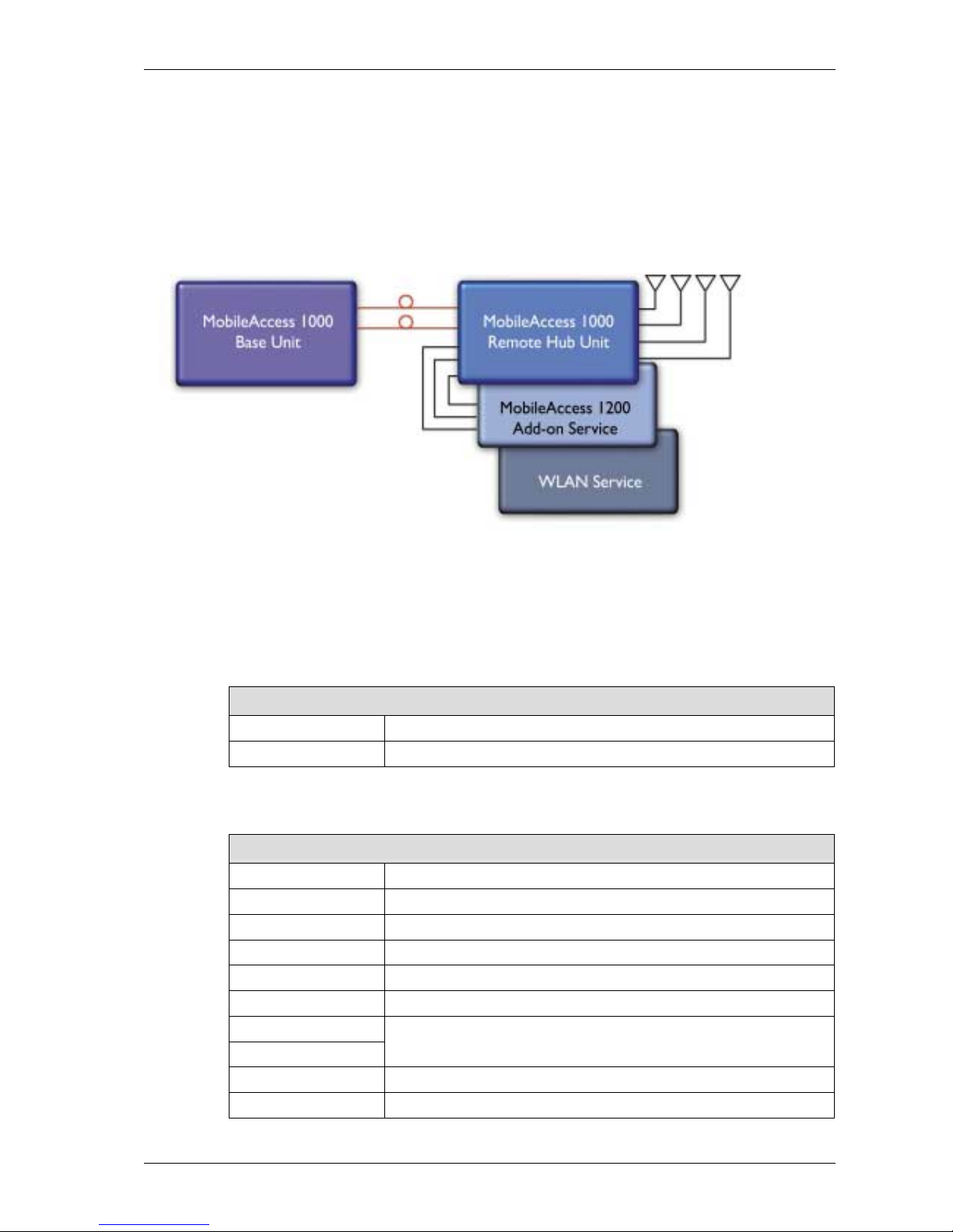
C) Using the MobileAccess 800 WLAN module to provide access to high
data-rate service
In the third conf iguration, depicted below, the W LAN module (MobileAccess™ 800)
is added. The WLAN module may also be added without the MobileAccess™ 1200
unit.
Figure 1-4. MobileAccess 1000/1200 BU – RHU Plus Add-on Plus WLAN Configuration
1.4 MobileAccess Models
Table 1-1: MobileAccess™ BU Models
MobileAccess Universal Base Units (1000, 1200, 2000 support)
WB-B8U Wide Band Base 8 Unit supporting 8 RHUs
WB-B4U Wide Band Base 4 Unit supporting 4 RHUs
Table 1-2: MobileAccess™ RHU Models with Add-on Capabilities
MobileAccess 1000 RHUs (ready for add-on units)
1000S-CELL-4 Single band-Cellular, 4 ports
1000S-IDEN-4 Single band-iDEN, 4 ports
1000S-PCS-4 Single band-PCS 4 ports
1000D-IDEN-PCS4 Dual band-iDEN/PCS, 4 ports
1000D-SMR-PCS4 Dual band-SMR/PAGING/PCS, 4 ports
1000D-CELL-PCS4 Dual band-Cell/PCS, 4 ports
1000D-CELL-DCS4 Dual band Cell/DCS 4P ready for add-on units
1000D-CL-M-DCS4 Dual band Cell multi operator/DCS 4P ready for add-on units
1000D-GSM-DCS4 Dual band GSM/DCS 4P ready for add-on units
1000D-GSMO-DCS4 Dual band GSM orange/DCS 4P ready for add-on units
Page 16

Introduction MobileAccess™ 1000/1200
6 UM-1000, Revision 2.2
Table 1-3: MobileAccess™ RHU Models
MobileAccess 1000 RHUs (Litenna compatible)
10L-D-IDEN-PCS4 Dual band-iDEN/PCS, 4 ports, LBC
10L-D-SMR-PCS4 Dual band-SMR/PAGING/PCS, 4 ports, LBC
10L-D-CELL-PCS4 Dual band-Cell/PCS, 4 ports, LBC
10L-D-CELL-DCS4 DB Cell/DCS 4P ready for add-on units-LBC
10L-D-CL-M-DCS4 DB Cell multi opr/DCS 4P ready for add-on units-LBC
10L-D-GSM-DCS4 DB GSM/DCS 4P ready for add-on units-LBC
10L-D-GSMO-DCS4 DB GSM orange/DCS 4P ready for add-on units-LBC
Table 1-4: MobileAccess™ 1200 RHU Models
MobileAccess 1200 RHU
1200-PCS-SA-1 Stand Alone high power PCS , one port
1200-UMTS-SA-1 Stand Alone high power UMTS, one port RHU
1200-PCS-AO Add-on RHU supporting a PCS service
1200-UMTS-AO Add-on RHU supporting UMTS service
Table 1-5: MobileAccess™ UMTS Ready RHU Models
MobileAccess 1200 RHU(Litenna UMTS Ready compatible)
12L-UMTS-AO Add-on RHU supporting UMTS service LBC
Table 1-6: MobileAccess™ Controller Models
Network Controller
410 Network Controller – Serial Interface (dial-up)
430 Network Controller –Ethernet/IP Interface
Table 1-7: MobileAccess™ Management System
Network Management System
NMS-SW-SERVER GUI and server S/W package (one per site)
NMS-SW-MFEE NMS annual S/W maintenance fee (per 430-CTLR)
Page 17

MobileAccess™ 1000/1200 Introduction
UM-1000, Revision 2.2 7
Table 1-8: MobileAccess™ RIU
Radio Interface Unit
RIU-IM Radio Interface Unit
RIU-BTSC-CELL BTS Conditioner for Cellular
RIU-BTSC-IDEN BTS Conditioner for iDEN
RIU-BTSC-PCS BTS Conditioner for PCS
RIU-BTSC-SMR BTS Conditioner for SMR-Paging
RIU-BTSC-GSM BTS Conditioner for GSM 900MHz
RIU-BTSC-GSM-O BTS Conditioner for GSM 900MHz for Orange
RIU-BTSC-DCS BTS Conditioner for DCS 1800MHz
RIU-BTSC-UMTS BTS Conditioner for UMTS 2100MHz
Page 18

Infrastructure Preparation MobileAccess™ 1000/1200
8 UM-1000, Revision 2.2
Chapter 2. Infrastructure Preparation
This following installation rules are based on the assumption that site survey and
installation planning (including power requirements) have been completed.
2.1 Basic Installation Rules
2.1.1 Fiber Optic Rules
• Use only single mode fiber for indoor applicat ions.
• Use only SC/APC connectors (green color).
• Use only fusion splice for connecting two fiber s.
• Use minimum splicing/connectors to achieve minimum losses on the fibers
(<0.5dB).
• Use precaution while installing, bending, connecting fiber optic.
• Use an optical power meter and OTDR for checking the fiber optic cables.
• Make sure the environment is clean while connecting/splicing fiber optic
cables.
• Verify the Fiber Optic connections. You may use the Optical Test Procedure
described in Appendix I: Optical Test Procedure.
• Pay special attention while connecting the SC/APC connectors - you must
hear the “click” when the connection is made.
2.1.2 RF Rules
• Use coax ½”, 50ohm, male-to-male N-type, (6- 7dB for 1Ghz, 11dB f or 2Ghz)
for connecting to RHU ports .
• Use coax RG223, 50ohm, male-to-male N-type f or connecting RF side from
the Base Unit to the BTS/RBS side.
• When using the MobileAccess™ system in an environment in which other
indoor coverage systems are installed, pay special attention t o the isolation
between antennas (distance must exceed 2 meter).
• Use special attention while bending coax cables, according the coax
specification.
• Use any antennas suitable to the desired frequency.
• Use VSWR meter (Site Master) for checking coax cables, including the
antennas. (<2).
• Unused RHU and RIU ports should be terminated with a 50ohm load.
Page 19

MobileAccess™ 1000/1200 Infrastructure Preparation
UM-1000, Revision 2.2 9
2.2 Power Consumption, Connections and
Power Supplies
Calculate the required power according to the requirements of the specific
installation and then determine the config urat ion of the power supplies. T he req uired
DC cables will then be determined by the selected PS configuration.
2.2.1 Power Consumption of Units
Table 2-1. MobileAccess™ Power Requirements
Unit Type Voltage Input
Power
Consumption
RIU 20 to 48VDC 10W
Base Unit 20 to 48VDC 14W
Remote Hub Unit 1000 20 to 48VDC 25W
Add-on Unit 1200 20 to 48VDC 50W
410/430 Controller 20 to 48VDC 10W
2.2.2 Power Supply Configurations
Two Power Supply configurations are usually in use:
• Individual connections - each PS is located adjacent t o the BU or RHU unit
it will serve
• Central connection – a single power supply supplies the power for all BUs
and RHUs
Page 20

Infrastructure Preparation MobileAccess™ 1000/1200
10 UM-1000, Revision 2.2
2.2.3 Types of Power Supplies
MobileAccess supplies various power supplies that can be installed in a rack or
mounted on a wall, depending on your configuration. Four power supply options are
available:
Table 2-2: MobileAccess™ Power Supplies
Power Supply
LPS-48V-40W Local AC/DC Converter 40W
LPS-48V-100W Local AC/DC Converter 100W
RPS-200-N-48 Non-redundant 200W 110/220V Wall Mount
RPS-500-R-48 Redundant 500W 110/220V Chassis Mount
RPS-1000-R-48 Redundant 1000W 110/220V Chassis Mount
RPS-14-50W-48 Remote power supply,14 modules of 50W,48V
RPS-14-100W-48 Remote power supply,14 modules of 100W,48V
RPS-6M-220 Remote power supply enclosure,6 Modules,220v in-48VDC
RPS-600W-220 Remote power supply module 600W/48VDC,220V in
RPS-1200W-220 Remote power supply module 1200W/48VDC,220V in
Page 21

MobileAccess™ 1000/1200 Infrastructure Preparation
UM-1000, Revision 2.2 11
2.3 Single-building Installation
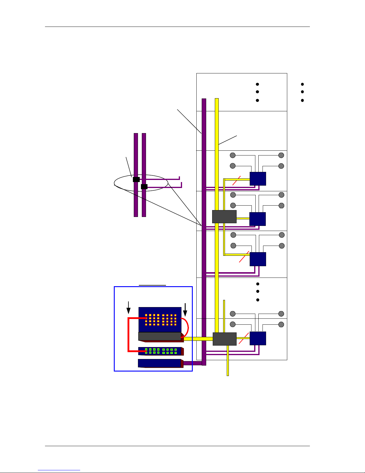
Single building installation conventions:
• Base Units – placed in the same location (usually in the communication
room).
• RHUs – usually placed in the communication shaf t of the cor responding f loor
so they can be easily located. A single RHU can typically cover a floor of up
to 30,000 sq ft.
• Fiber optic cable - Bundled fiber from the Patch Panel located in the
communication room rack is also rout ed through the building shaft to splice
boxes located every three floors where a Splice Box is used to split a t ube of
six fibers to three pairs of fibers. A pair of fibers is routed to the
corresponding floor, to the floor above and to the floor below.
• Single source power cable – a single thick power cable runs from the
communication room through the building shaft. The power is distributed to
each floor using two thin cables that are connected to t he thick power cable
using DC clamps. The thin cables provide power to the individual RHUs on
each floor.
• On each floor, connect F/O and power to the corr esponding RHU. Connect
antennas to RHU using via coax cables.
Page 22
Infrastructure Preparation MobileAccess™ 1000/1200
12 UM-1000, Revision 2.2
The following page shows an example of routing of Fiber Optic and power cables in
a multi story building using the installation conventions previously described.
Floor 9
Floor 2
RHU
2 Pigtail
Fibers
Fiber Optic
Cable
Floor 7
2 Pigtail
Fibers
Patch panel
B8U
SC/APC
PigTail
SC/APC
Jumpers
Splice
box
RHU
RHU
RHU
19" Rack
Power Supply
DC
Cable
Splice
box
Floor 30
Floor 8
D.C
Clamp
2 Pigtail
Fibers
Figure 2-1- Fiber Optic and Power Cables Routing Example
Page 23
MobileAccess™ 1000/1200 Infrastructure Preparation
UM-1000, Revision 2.2 13
2.4 Horizontal Layout Installation
Horizontal layout installation conventions:
• Connect a separate optic fiber to every site location, where a site may include
more than one RHU.
• The connection may be to a splice box or directly to the RHU (depending on
the site configuration).
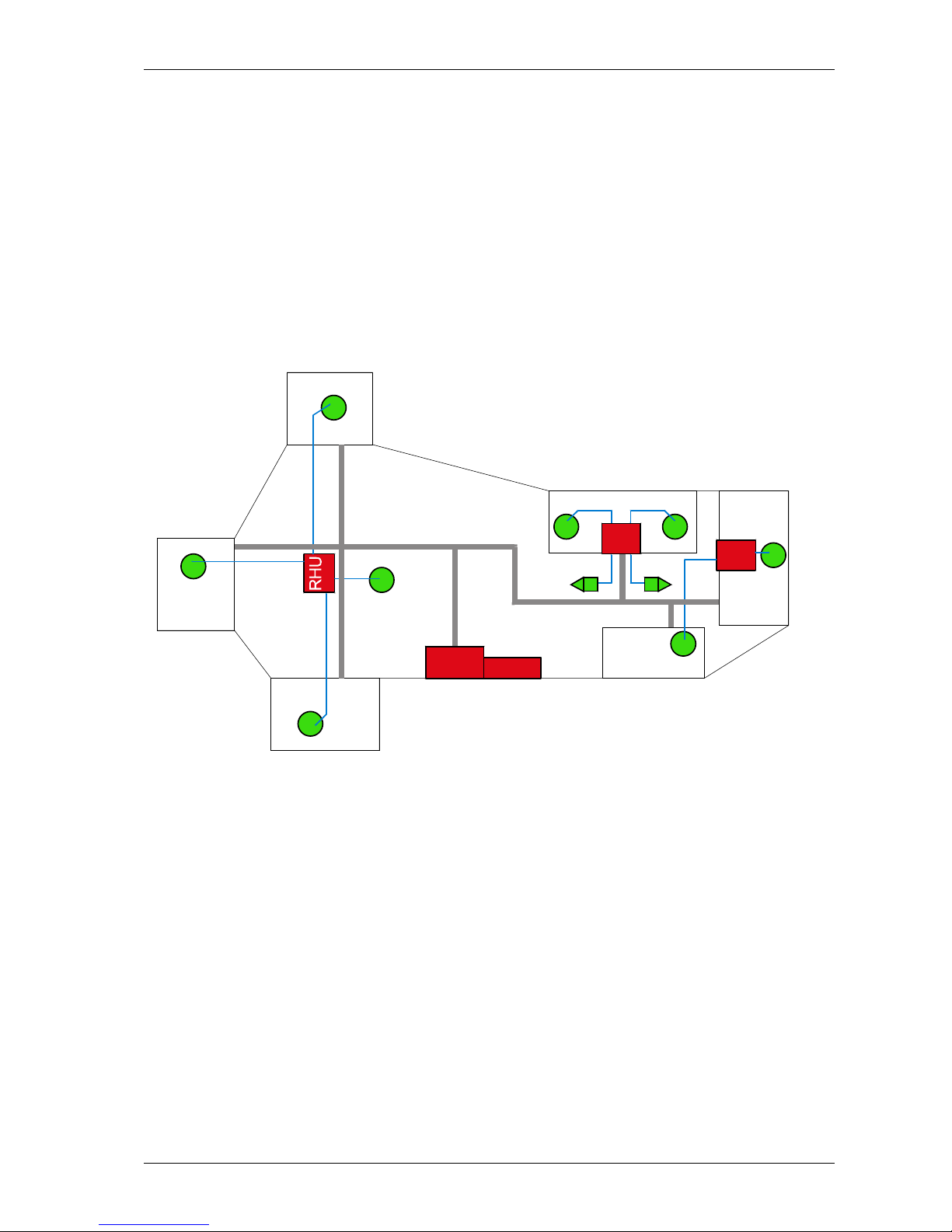
The following figure shows a horizontal layout installation with three RHUs
connected to a number of antennas.
RHU
RHU
CELL
SITE
BU
A
B
C
D
E
F
G
I
H
Figure
2-2: Horizontal Layout Installation
Page 24

Connections MobileAccess™ 1000/1200
14 UM-1000, Revision 2.2
Chapter 3. Connections
3.1 Rack Installation
It is recommended to install the following MobileAccess system modules in a 19”
rack (usually in the communication room):
• RIU 3U
• BU 1U
• MobileAccess 410/430 controller 1U
• Fiber Optic patch panel and splice tray
• Power supply/supplies (MobileAccess – 3U for each unit, units from other
manufacturers may vary in size)
Verify that the rack height can support all the unit s to be installed, where you may
also want to consider future expansions.
The following image describes shows the recommended locations of the
MobileAccess elements in the rack in order to facilitate and simplify the cabling
connections. Note that the MobileAccess 410/430 controller is at eye level to
provide an easy view of the LED indicators and LCD display and easy access to the
local and remote monitoring connections.
Figure 3-1: Recommended Order In Rack
MobileAccess Controller (1U)
MobileAccess RIU (3U)
MobileAccess
Power Supply (3U)
Fiber Optic Patch Panel
and Tray (variable size)
At eye level
MobileAccess Base Unit 6 (1U)
MobileAccess Base Unit 1 (1U)
MobileAccess Base Unit 2 (1U)
Page 25
MobileAccess™ 1000/1200 Connections
UM-1000, Revision 2.2 15
3.2 Module Descriptions and Connections
3.2.1 Radio Interface Unit (RIU)
Each RIU can support up to three BTS Conditioner (BTSC) sub-modules, where
each sub-module provides interface to a BTS or BDA. The BTS or BDA service must
correspond to the type of BTSC to which it is connected.
Each RIU can be connected to four 8-port Base Units (real panel connections) or
eight 4-port Base Units. The RIU can be expanded to support additional BU by
using splitters and combiners connected to the front panel connect ors.
Note: All connections are via RG223 coax cables with 1/2" N-type male connectors
3.2.1.1 RIU Front Panel
The RIU front panel contains all the indicators and LEDs. The wiring connections on
the front panel are used to com bine the RF signals into a single signal that is applied
to all BUs.
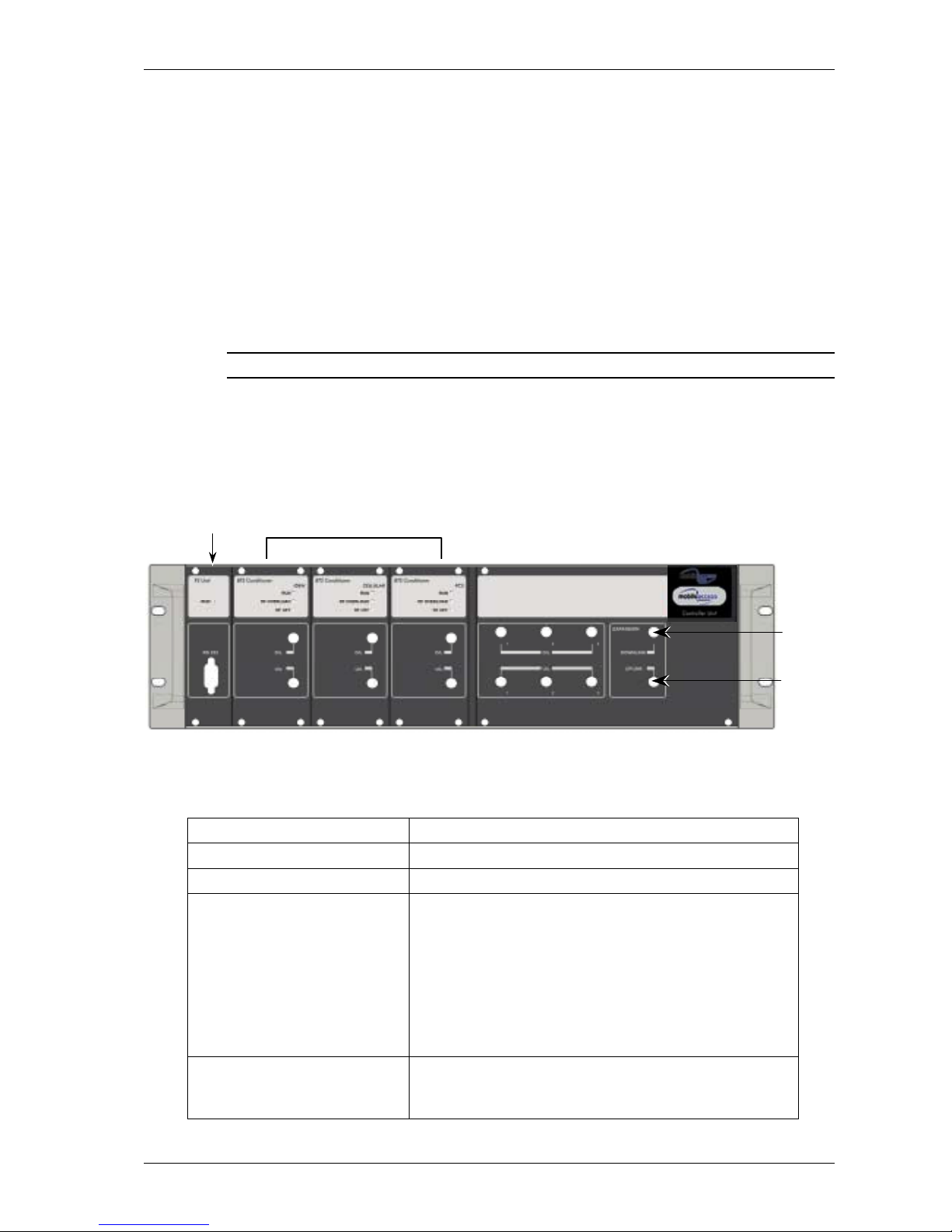
Figure 3-2. RIU Front Panel
Table
3-1. RIU Front Panel Indicators
LED Description
P.S UNIT PWR
ON – input signal is at the required level.
BTS CONDITIONER RUN
Flashing -- CPU is running and software loaded
BTS CONDITIONER DL OVERLOAD
Continuous Red – RF switch is disconnected to protect
the system. This may be due to:
• Unpredicted power rise for which the attenuation
response was insufficient to compensate and reduce
the power to the required level.
• Software problem detected.
Flashing: When the BTSC DL output power is more than
3dB of the calibrated value.
BTS CONDITIONER DL LOW
Continuous Red – if the BTSC DL power is at least 15dB
lower than the calibrated BTSC max power level. This
condition also triggers an event.
Power Supply BTS Conditioners
8W Splitter
8W Combiner
Page 26
Connections MobileAccess™ 1000/1200
16 UM-1000, Revision 2.2
3.2.1.2 RIU Rear Panel
The rear-panel provides all the connections on the BT S side and on the BU side as
well as connections to the MobileAccess 410/430 controller and the power
connection. Two types of BTS side connections are available for each BTS
conditioner: simplex and duplex.
ATTENTION
1. The RIU is factory set to 0dB gain on the uplink and
downlink. In order to operate properly, an ADJUSTMENT
process is required in the field.
2. Any unused input and output connectors MUST be
terminated with 50 ohms – otherwise the ADJUSMENT
procedure results may be affected.
3.2.1.3 RIU Connections
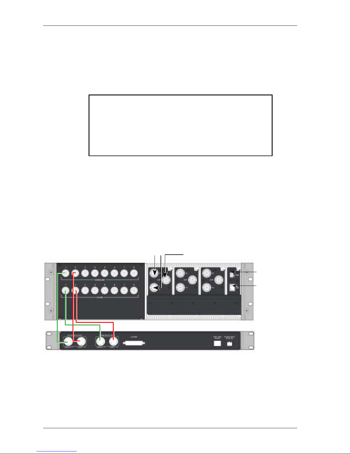
1. Connect each Base Unit to the corresponding pair of RF outputs on the RIU
rear panel. Note that one uplink and one downlink RIU rear-panel connector
is used to connect one OPTM (four ports from the BU). To connect
additional BUs, refer to Connections to Additional BUs.
2. Connect the BTS/BDA connections (either simplex or duplex), the controller,
and the power connections.
Figure
3-3. RIU Rear Panel showing the RF Connection
MobileAccess 1000 BU
connections (pair per BU)
DC power input
MobileAccess 410/430
controller connection
BTS/BDA simplex
connection
BTS/BDA duplex
connection
Page 27
MobileAccess™ 1000/1200 Connections
UM-1000, Revision 2.2 17
3.2.1.4 Connections to Additional BUs
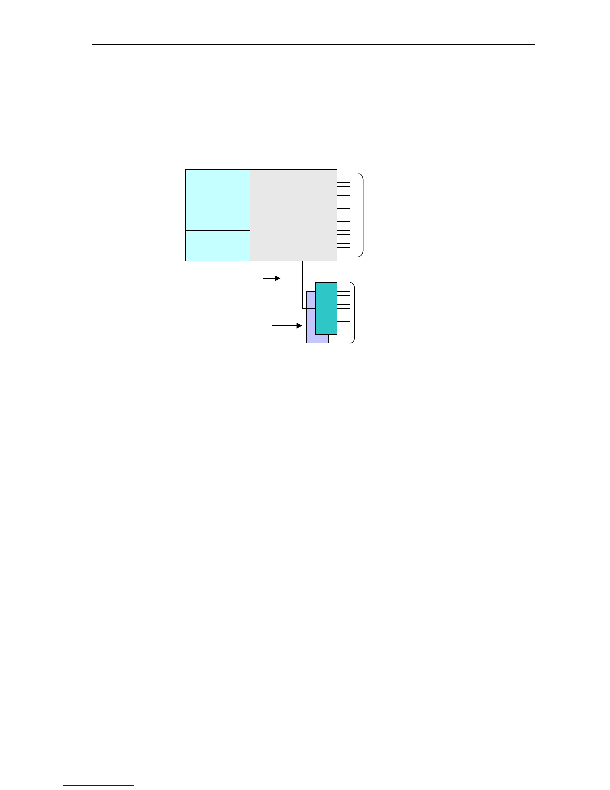
To connect more than four 8-port BUs or more than eight 4-port BUs to the RIU,
Connect an 8W splitter to the Downlink connector on the RIU front panel and an 8W
combiner to the Uplink connector on the RIU front panel and connect additional BUs
to the uplink and downlink connections.
Expansion ports
BTSCBTSC
BTSCBTSC
BTSCBTSC
Combiners
/Splitters
Compartment*
UL and DL
connections to
four BU8 modules
UL and DL connections
to up to four additional
BU8 modules
External 1:8 splitter
/combiner
Page 28
Connections MobileAccess™ 1000/1200
18 UM-1000, Revision 2.2
3.2.2 Base Units
Depending on the Base Unit model, each Base Unit drives up to four or eight
remotes via duplex F/O connection, where each remote can be as far as 2
kilometers (1¼ m iles) from the BU. Eight port BU consist of two four port BU that
are integrated.
During power-up, the Base Unit identifies the active connected RHUs that are
connected to that Base Unit and each of the corresponding link LEDs is lit according.
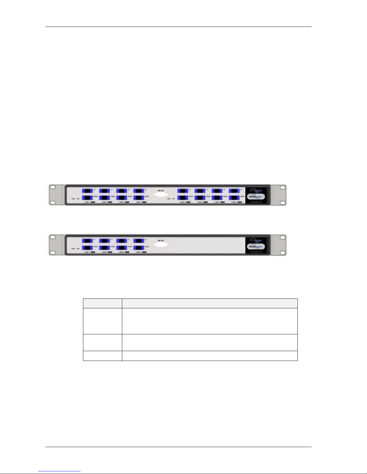
3.2.2.1 BU Front Panel
The front panel contains all the optical connect ions. The following figures show the
two configurations in which the BU is available.
Figure 3-4. Eight Port MobileAccess 1000 Base Unit Front Panel
Figure 3-5. Four Port MobileAccess 1000 Base Unit Front Panel
Table 3-2. MobileAccess BU 1000 Front Panel Indicators
LED Description
Link 1-8
ON - the optical link between the BU and RHU functions within the
specifications in both directions.
Blinking - optical power from RHU exceeds 2dBm.
LSR
ON - laser circuitry for the corresponding RHUs (1-4 or 5-8) is
functioning correctly.
PWR Power ON
Page 29
MobileAccess™ 1000/1200 Connections
UM-1000, Revision 2.2 19
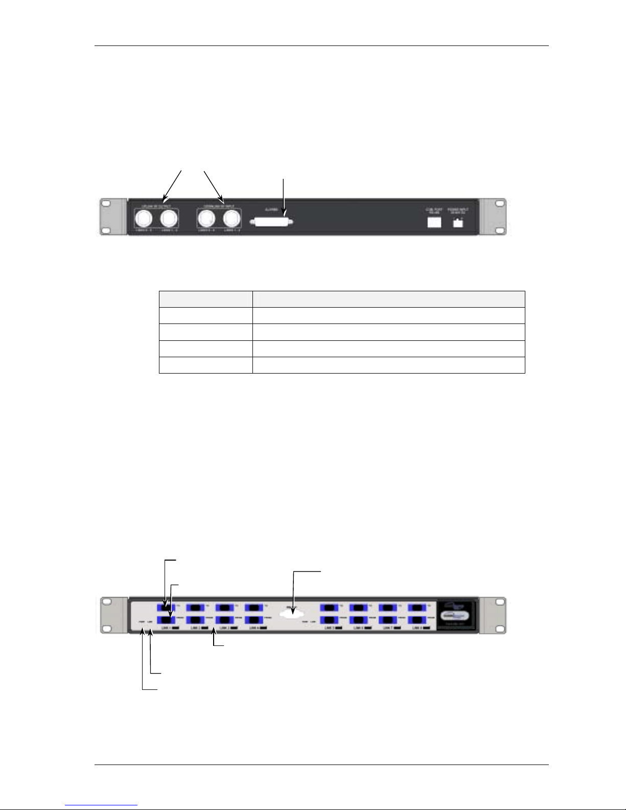
3.2.2.2 BU Rear Panel
The BU rear panel contains all the RF connections.
Figure 3-6. Base Hub Unit Rear Panel (RF Connections)
Table
3-3. MobileAccess 1000 Front Panel Indicators
Connector Description
Uplink output Uplink connectors to be connected on BTS side.
Downlink input Downlink connectors to be connected on the BTS side.
Com Port RS485 Connection to MobileAccess 410/430 controller.
PWR Power connection
3.2.2.3 Base Unit to RHU connections
1. It is assumed that the patch panel cabinet (SC/ APC adapt or s) for fiber optic
cable connections is installed in the rack near the Base Units.
2. Connect (3/125/900) pigtail with SC/APC connector s between splice
tray and patch panel cabinet.
3. Connect (3/125/3000) SC/APC jumpers bet ween the corr esponding
Base Unit and patch panel.
4. Connect the fiber optic cables fr om the Base Unit to the RHU’s
through the patch panel cabinet.
Figure 3-7. Base Hub Unit Rear Panel (RF Connections)
Laser output connection
to RHU
Optical diode input
from RHU
Base Unit Laser
operational LED indicator
RHU LED indicators
(Link 1 to 8)
RS232 connection for
monitoring
Power indicator
Pair of uplink and downlink connections
for interface to BTS side (all four
connectors must be connected)
Alarms connector
Page 30
Connections MobileAccess™ 1000/1200
20 UM-1000, Revision 2.2
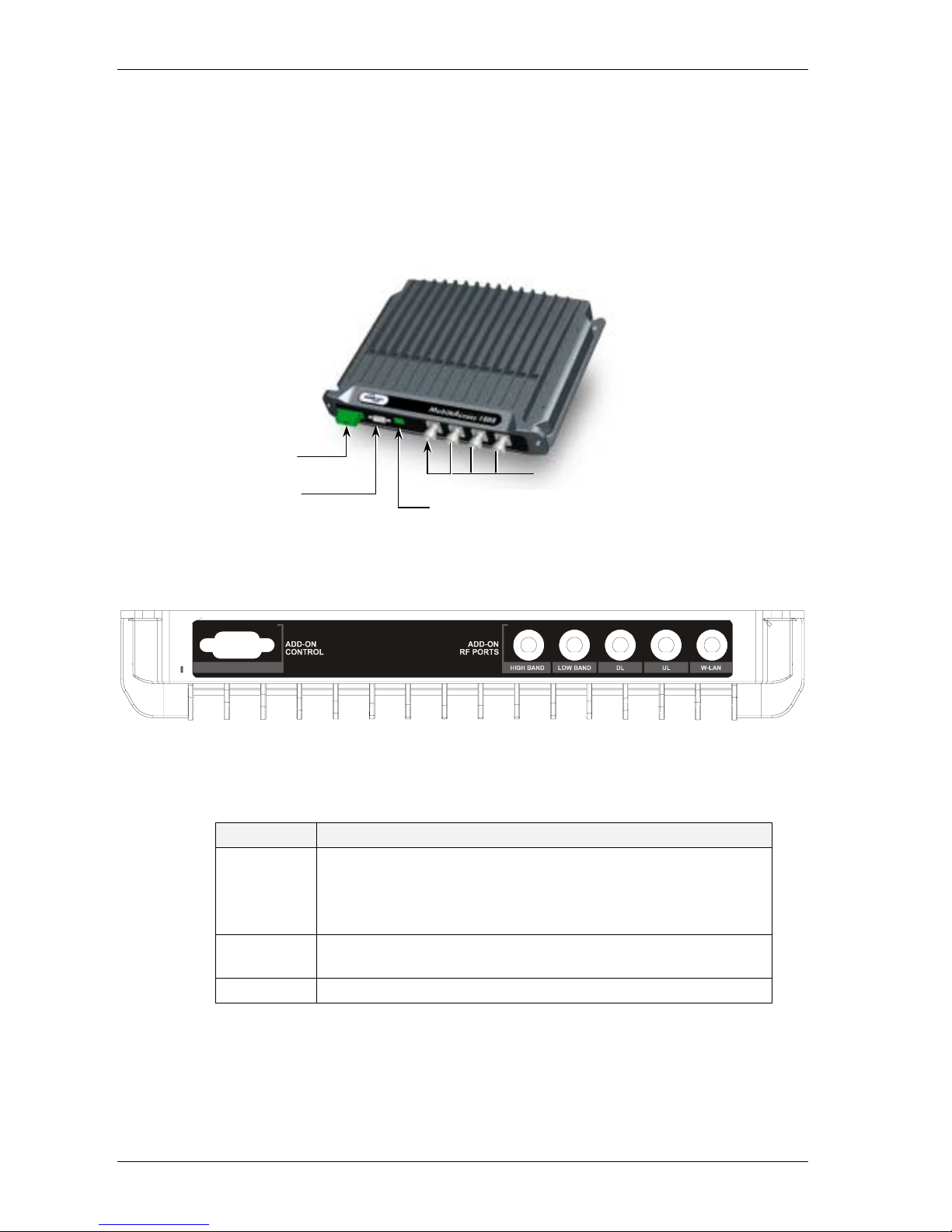
3.2.3 Remote Hub Unit (RHU) 1000
Supports two different frequency bands depending on the RHU 1000 model.
Output composite power per antenna port is in the range of 14 to 20 dBm
(depending on the served protocol). In order to supply antenna alarms, the
antenna must provide a DC resistance of up to 5K ohms.
Figure 3-8. RHU 1000
Figure 3-9. RHU 1000 Rear Panel
Table 3-4. MobileAccess 1000 Front Panel Indicators
LED Description
Link
When on constantly, the LED indicates that the received optical
power from BU functions within the specifications.
When it blinking, it indicates that the optical power from BU is
higher than 2dBo.
RUN
When blinking, indicates that the CPU in the RHU is in normal
operating mode.
DC Power ON
Cellular external
antennas connections
Optical input/output connectors
to/from Base Units
DC power connector
RS232 connector for MobileAccess
service personnel
Page 31
MobileAccess™ 1000/1200 Connections
UM-1000, Revision 2.2 21
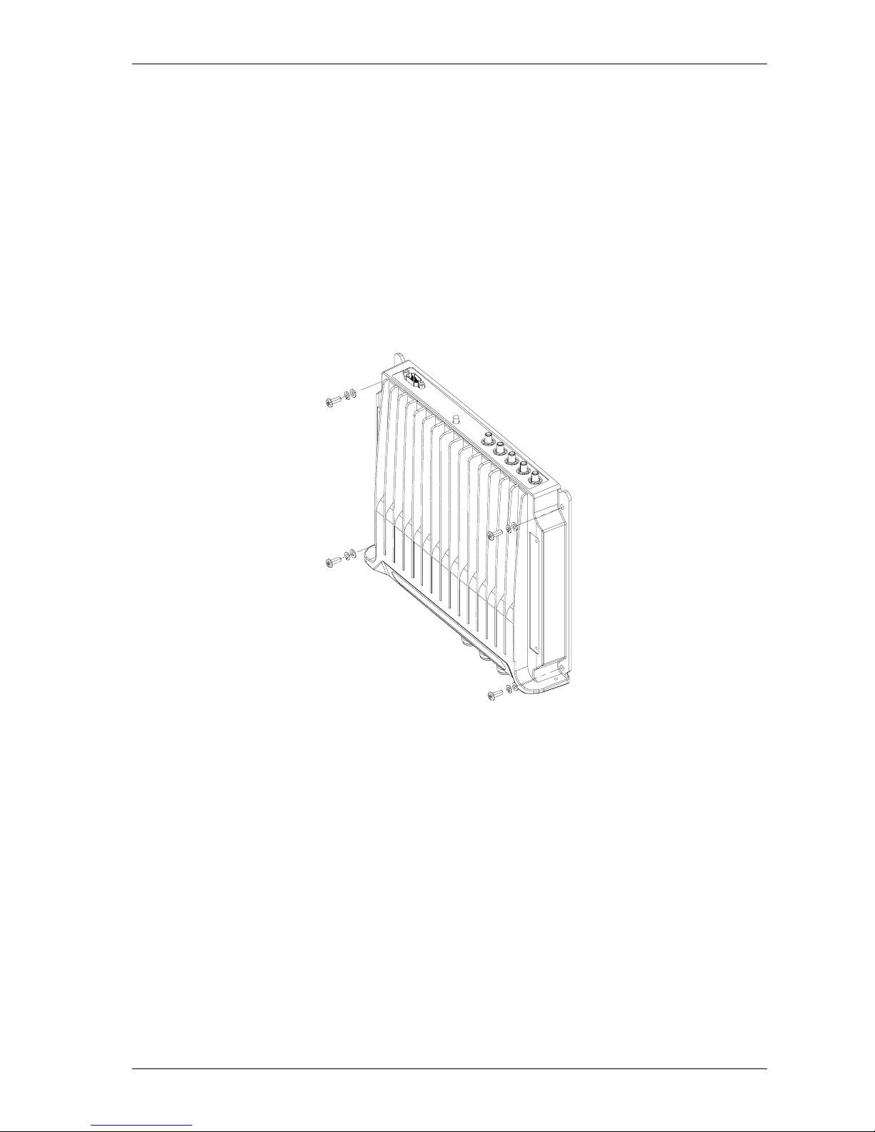
3.2.3.1 Wall Mount
RHU 1000 is usually mounted on a wall in a clean indoor environment – RF ports
facing down.
Assembly instructions
1. Place the unit against the wall and mark the four holes to be drilled in the wall.
2. Drill four holes 8mm in diameter and inser t the appropriate sized plastic plugs in
each hole.
3. Secure the RHU 1000 to the wall using four screws, 4.5mm diameter, 40mm
long.
Figure 3-10. RHU 1000 Wall Mount
3.2.3.2 Connections
1. Install splice box near RHU (refer to Figure 2-1).
2. Connect fiber optic cable to splice box and to SC/APC pig t ails to RHU
3. For the downlink, connect the fiber optic cable pigtails from splice box
coming from the Base Unit port to the corresponding Remote Hub
Unit port.
4. Connect the Remote Hub Unit to antennas according to the RF
engineers design. (up to 4 antennas per RHU) .
5. For the uplink, connect the f iber optic cable pigtails from splice box
from the Remote Hub Unit t o the uplink port that connects to the Base
Unit.
Page 32
Connections MobileAccess™ 1000/1200
22 UM-1000, Revision 2.2
6. Connect the power to each RHU according to power design planning
(local or remote power supply).
7. Verify that 50ohm terminators ar e placed on t he unused uplink and
downlink connectors.
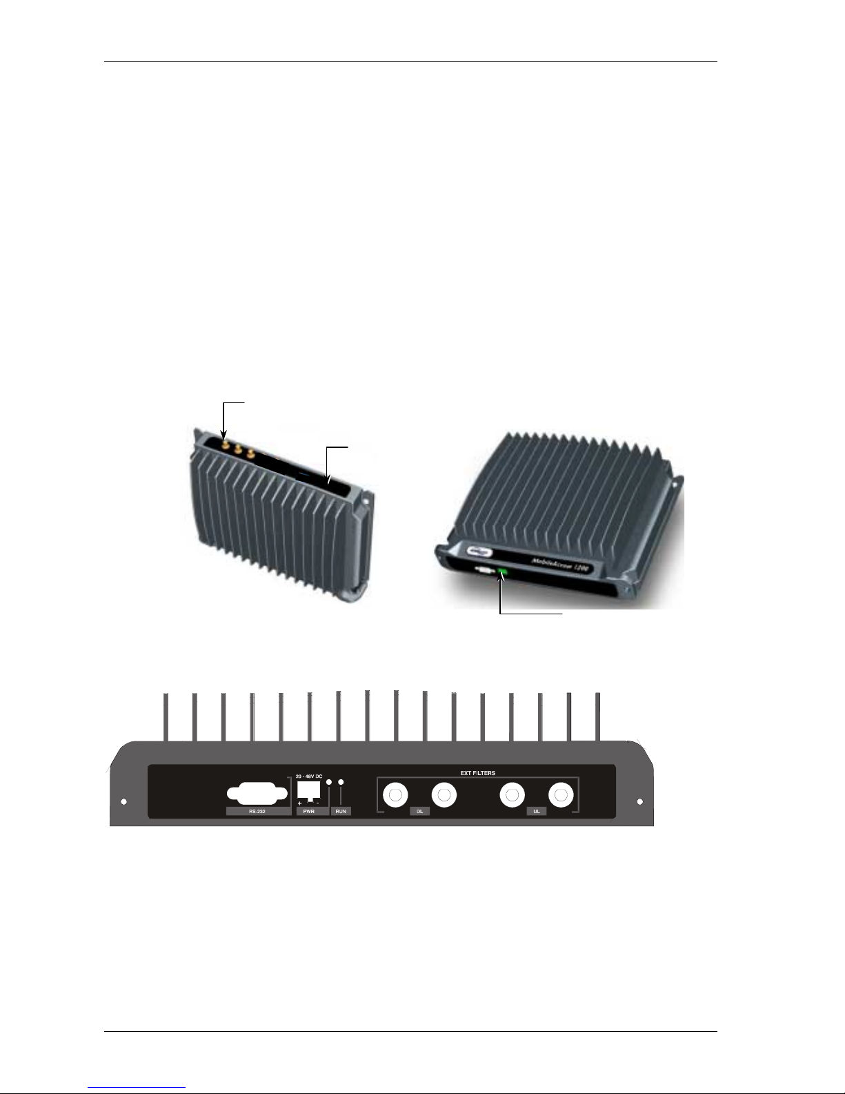
3.2.4 RHU 1200
High power module, supporting a single frequency band (low or high). The frequency
band depends on the model. RHU 1200 is supplied in two configurations: add-on
and standalone.
RHU 1200 add-on model is assembled onto the RHU 1000 model using the supplied
bracket. RHU 1200 does not requir e any additional RF or optic infrastructure since
all signals are received through the RHU 1000 unit to which RHU 1200 is
assembled.
Figure 3-11. RHU 1200 Front and Rear panels
Figure 3-12. RHU 1200 Rear Panel
SMA Uplink, Downlink
and High
Connection to
RHU 1000
DC Power
Page 33
MobileAccess™ 1000/1200 Connections
UM-1000, Revision 2.2 23
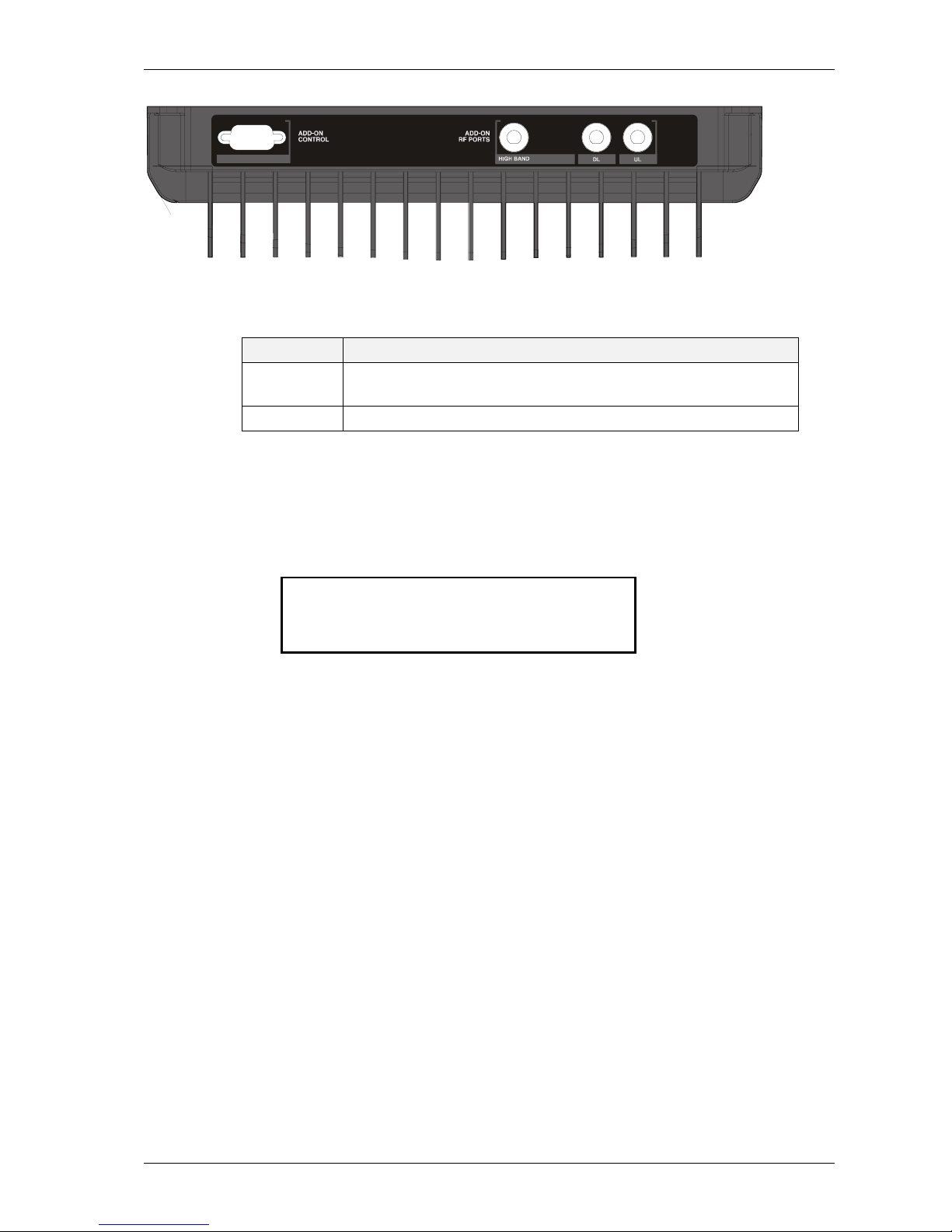
Figure 3-13. RHU 1200 Front Panels
Table
3-5. MobileAccess 1000 Front Panel Indicators
LED Description
RUN
When blinking, indicates that the CPU in the RHU is in normal
operating mode.
DC Power ON
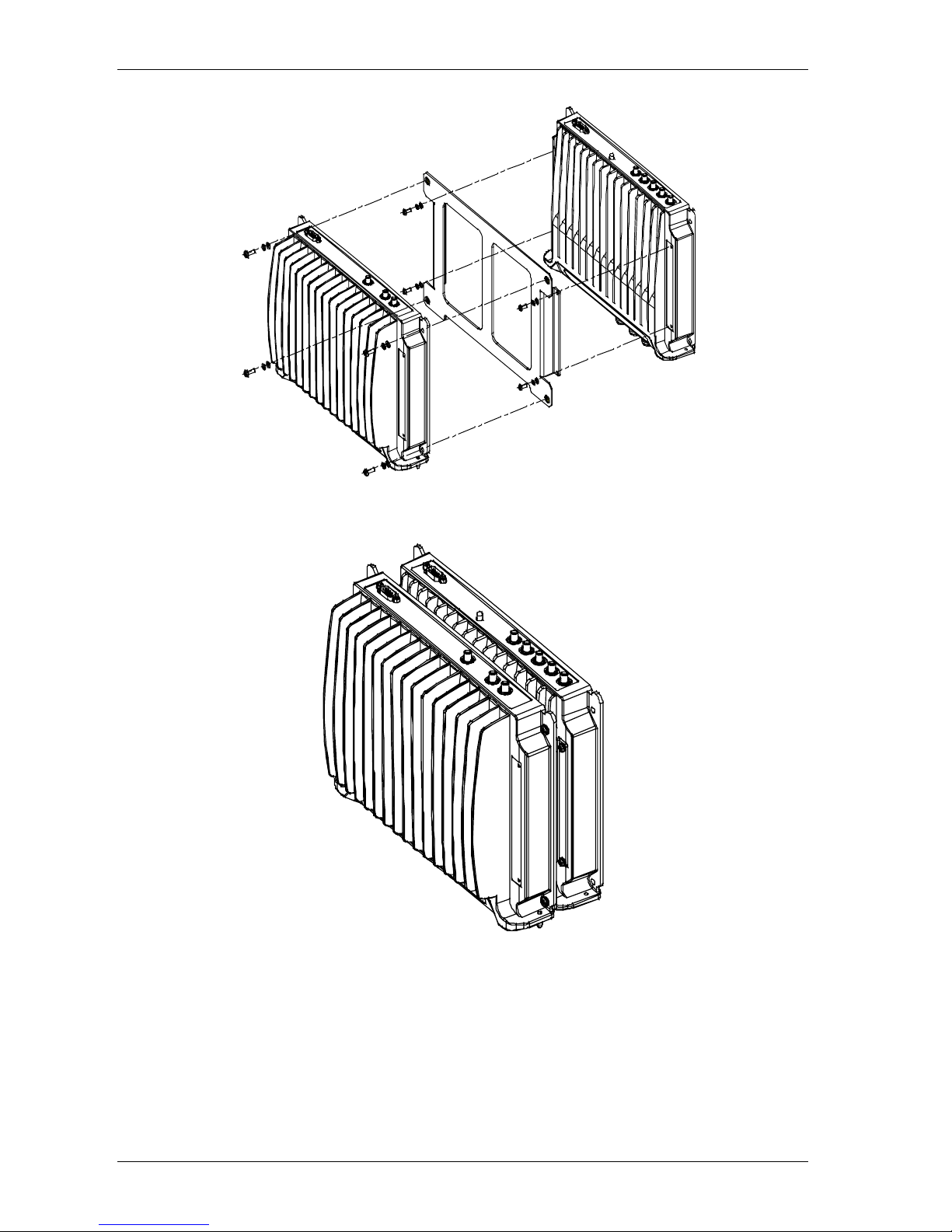
3.2.4.1 Assembly and Connections
Refer to Figure 3-14.
ATTENTION
To prevent damaging the SMA connectors,
be sure to tighten using a torque of 8lb.
1. On the RHU 1200 front panel, short ( i nt erconnect) the pair of SMA Downlink
connectors to each other using the ‘U-shaped’ jumpers, and the pair of SMA
Uplink connectors to each other. Using the second U-shaped jumper.
2. Position the supplied bracket on the RHU 1000 and secure the bracket to the
RHU 1000 using the four supplied 6-32 NC screws.
3. Position the RHU 1200 unit on the bracket and secure t he RHU 1200 to the
bracket using the four supplied 8-32 screws.
4. Interconnect the RHU 1000 and RHU 1200 SMA Uplink, Downlink and High
connectors on the rear panels of both units using the three straight jumpers.
5. Interconnect the RHU 1000 and RHU 1200 D-type 9-pin connectors on the rear
panels of both units using the supplied flat-cable.
6. Connect the power to the RHU 1200 front-panel DC connect or .
Page 34
Connections MobileAccess™ 1000/1200
24 UM-1000, Revision 2.2
Figure 3-14. RHU 1200 to RHU 1000 Assembly
Figure 3-15. RHU 1200 to RHU 1000 Completed Assembly
Page 35
MobileAccess™ 1000/1200 Connections
UM-1000, Revision 2.2 25
3.2.5 MobileAccess 410/430 Controller
NOTE: This section provides general information on the MobileAccess 410/430 Controller. For detailed
information on the controller, configuration and connections refer to the Mobile Access NMS User’s
Guide.
The MobileAccess controllers enable managing and controlling the MobileAccess
system elements. All the monitoring and contr ol operations can be performed f rom
the Master’s location.
Two MobileAccess controller configurations are provided: MobileAccess 410 and
MobileAccess 430. The models differ in their r em o t e access capabilit ies:
• MobileAccess 410 provides point-to-point connectivity implemented via either
direct RS232 connection or via connection to a DSPN phone line
• MobileAccess 430 provides client/server management capability over TCP/IP
network with enhanced monitoring and control capabilities (in addition to the
connectivity options provided by MobileAccess 410).
NOTE: The MobileAcces s 430 front panel is diff erentiated from the MobileAccess 410 f ront
panel by the SNMP Agent Card that provides TCP/IP management capabilities.
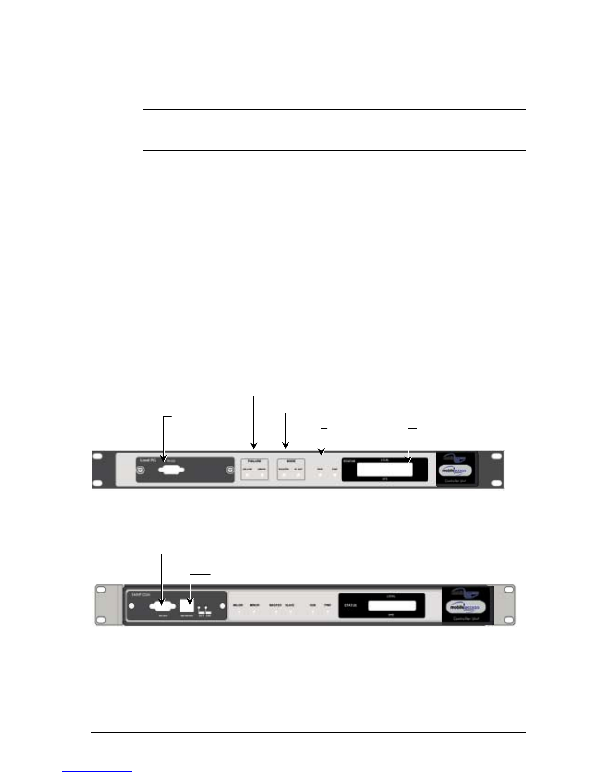
3.2.5.1 Controller Front Panel
Figure 3-16. MobileAccess 410 Front Panel
Figure 3-17. MobileAccess 430 Front Panel
Local RS232
connection (for IP
address setup)
LCD alarm display
corresponding to Major
and Minor LEDs
Major, Minor
LED indicators
Master/Slave configuration
Run and
Power LEDs
TCP/IP connection
Local RS232 connection to Laptop (MA 300
for Remote controller)
Page 36
Connections MobileAccess™ 1000/1200
26 UM-1000, Revision 2.2
3.2.5.2 Controller Rear Panel
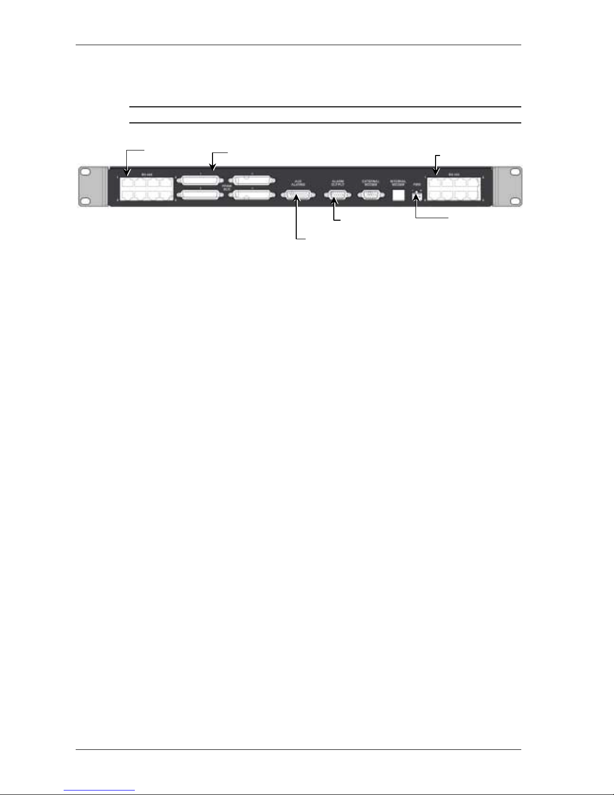
Note: The rear panels for the MobileAccess 410 and MobileAccess 430 are the same.
Figure 3-18. MobileAccess 410/430 Rear Panel
DC Input
General purpose
alarms input
BTS alarms output
(RF2MobileAccess).
MA BU and RIU
inputs
Slave controller
connections
Page 37

MobileAccess™ 1000/1200 Appendices
UM-1000, Revision 2.2 27
Chapter 4. Appendices
4.1 Appendix I: Optical Test Procedure
This section describes the methods applied to test fiber optic cable’s optical insertion
loss and return loss.
4.1.1 Fiber Optic Cable Test
Due to the extended distances that analog signal tr ansmissions travel on cable, the
major challenge is to determine the st at us of the cable.
In order to determine that the cables are functioning, technical personnel need to
perform optical power tests.
The optical power tests covered in this document are:
• Optical insertion loss measurement test
• Optical return loss measurement test
4.1.2 MobileAccess System Characteristics
The MobileAccess™ system consists of the following characteristics:
• Singlemode fiber
• Wavelength 1310nm
• Fiber Optic Cable Measurement Tests
Cable can be measured through several procedures. This docum ent describes the
following tests:
• Optical insertion loss measurement test
• Optical return loss measurement test
These tests are intended to be performed by technical personnel that deal with
MobileAccess systems. Other equipment can be used to perform these tests,
however the results have to be the same as will appear in the fiber optic cable test
results table (Table
4-1), at the end of this document.
The insertion loss measurement determines whether the optical signal power
traveling the cable leng th is strong enoug h to be received by the photo diode, in the
receiver.
Page 38
Appendices MobileAccess™ 1000/1200
28 UM-1000, Revision 2.2
Following the completion of the insertion loss test, the return loss test determines the
optical signal power that returns to the laser. The return power affects the laser,
changing the laser’s base current.
4.1.3 Test Equipment
In order to perform t hese t est s, the following equipment is necessary:
• Light source (for wavelength 1310nm , 0dbm )
• Optical power meter
• Optical coupler (hosed and connectorized)
• Fiber optic jumper
• Adapter parts for the cable connector s
For information about equipment suppliers, contact MobileAccess.
4.1.4 Optical Insertion Loss Measurement Test
The optical insertion loss measurement tests the attenuation of the cable. The
insertion loss’ value should be minimal and remain in scale to 0.4dB/Km.
The insertion loss measurement can be performed in two methods:
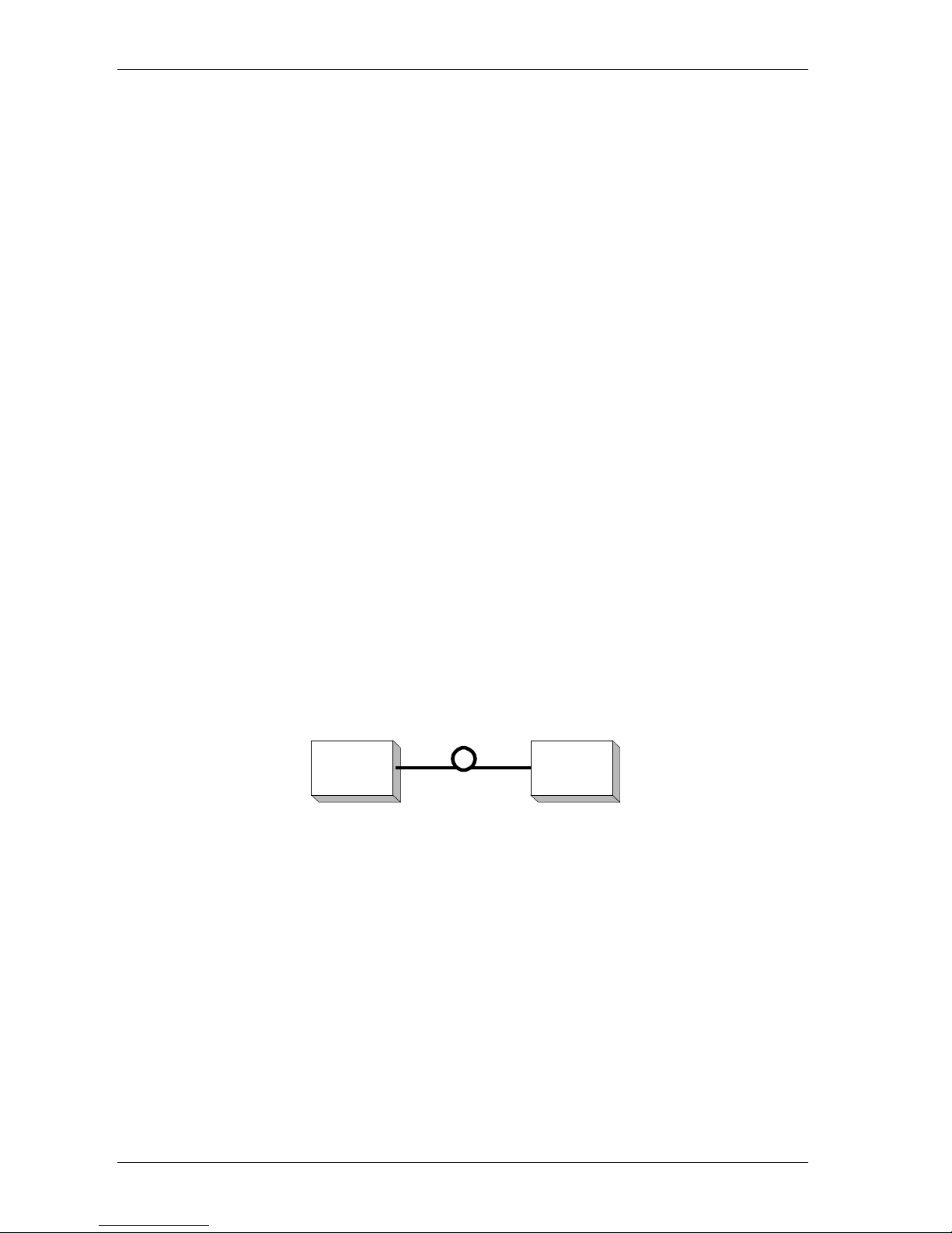
• Two point test
• Single point test
4.1.4.1 Method #1: Two Point Test
Connection description: Light source connected at one end of the cable and an
optical power meter at the other end.
Light
source
Optical
power
meter
Figure 4-1: Two Point Test
1. Connect light source directly to the optical power met er .
2. Measure light source signal power, verifying power of 0dBm.
3. Connect light source to cable end.
4. Connect optical power meter to cable at other end.
5. Measure light source signal power using the optical power meter.
6. Calculate the difference between two signals (dB) :
(Insertion loss)dB = (Light source signal at one end)dBm – (Measured signal at other end)dBm
Page 39
MobileAccess™ 1000/1200 Appendices
UM-1000, Revision 2.2 29
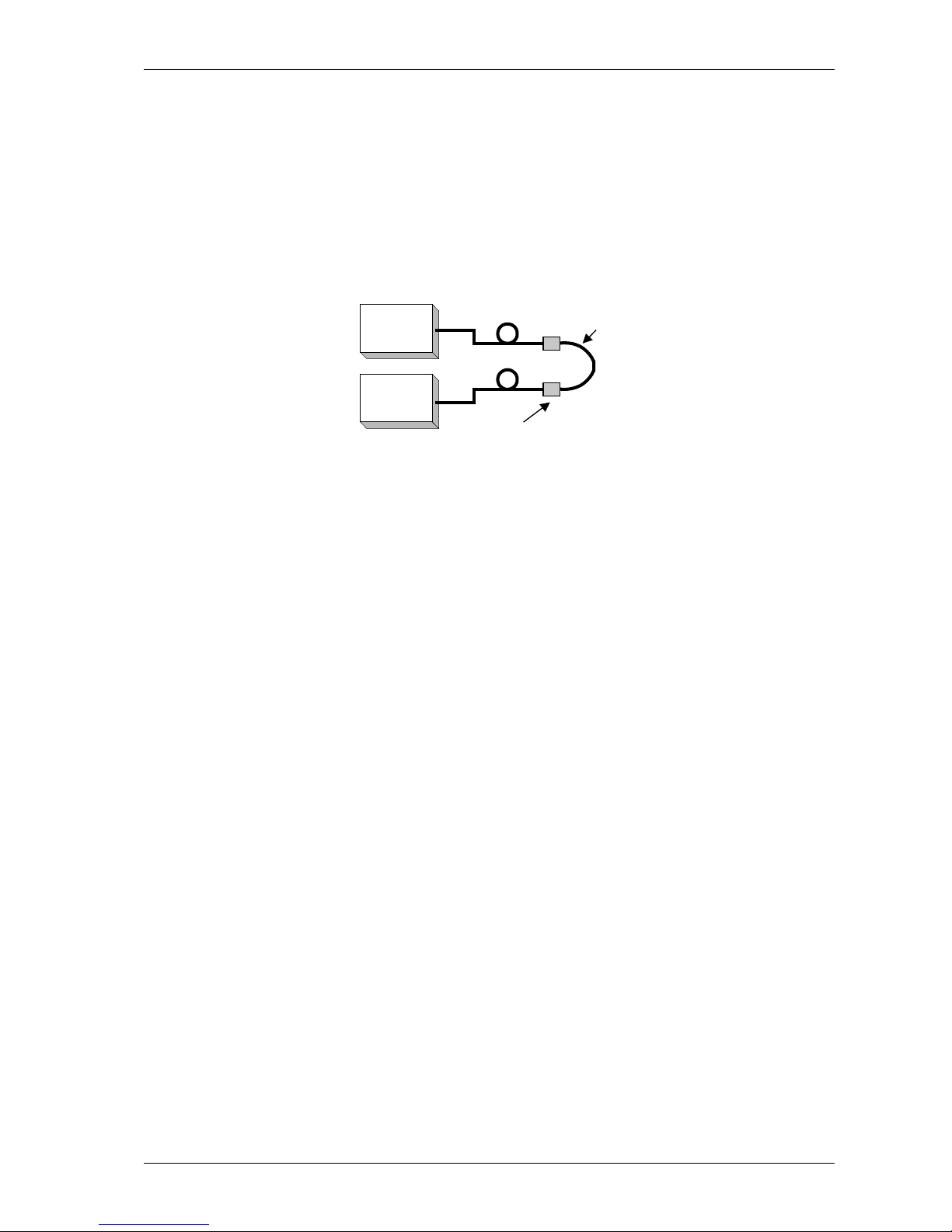
4.1.4.2 Method #2: Single Point Test
Connection description: This method assumes that t here are two parallel fibers on
the path to be tested. Connect fiber jumper at end of the cable being tested to
another parallel cable. Connect the light source, optical power meter and optical
jumper as shown in Figure
4-2. This measurement can test two cables
simultaneously.
Light
source
Optical
power
meter
Connector
Fiber optic jumper
Figure 4-2: Single Point Test
1. Use optic jumper to connect the two cables.
2. Connect light source directly to the optical power met er .
3. Measure the power of light source signal , verify power of 0dBm.
4. Connect a light source and optical power meter to one end of each cable.
5. Measure the power of the signal.
6. Calculate the difference between the two signals in dB
(Insertion loss)dB =(Light source signal)dBm– (Measure signal)dBm
4.1.5 Other Test Equipment
The optical insertion loss measurement test can be performed with more
sophisticated measurement equipment.
For information on other types of test equipment contact MobileAccess.
Page 40
Appendices MobileAccess™ 1000/1200
30 UM-1000, Revision 2.2
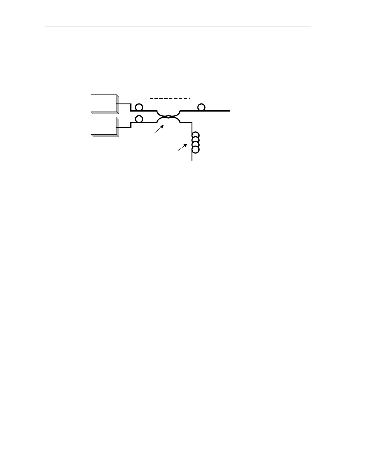
4.1.6 Optical Return Loss Measurement Test
Connection description: Connect a light source and optical power to the inputs. If the
coupler has one output, connect the tested cable t o this output. If the coupler has
two outputs make a pigtail at the second output.
Light
source
Optical
power
meter
IN OUT
(pigtail)
Cable Being Tested
2
1
3
4
"Optical Terminator"
Optical Coupler
Figure 4-3: Optical Return Loss Measurement
4.1.7 Measurement Procedure
4.1.7.1 Measuring Power Input To Cable Being Tested
• Verify that light source power is at 0dBm.
• Connect a light source to connector #1.
• Connect optical power meter to connector #3.
• Measure signal power (P3), power should be approximately –4dBm.
4.1.7.2 Measuring Coupler Power Loss
• Move power meter from connector #3 to connector #2.
• Move light source from connector #1 to connector #3.
• Measure power loss of coupler (Lc).
4.1.7.3 Measuring Return Power
To measure return power:
• Move light source from connector #3 to connector #1.
• Connect cable being tested to output connector #3.
• If coupler has two outputs, then mak e a pigtail at second output.
• If cable is longer than 100 meter , then cable needs to be isolated.
Page 41

MobileAccess™ 1000/1200 Appendices
UM-1000, Revision 2.2 31
To isolate cable:
1. Find place near test point where winding the cable into a pigtail is possible.
1. Make pigtail.
2. If cable is shorter than 100 meter , then verify that cable is disconnected at end.
3. Measure the return light power (P2), connector #2.
Calculating Return Loss
Calculate the difference between the sig nals in dB.
(Return loss)dB = (P2)dBm – (P3)dBm + (Lc)dB
4.1.8 Results
The following table is to be filled in by technical personnel testing the fiber optic
cables.
Table 4-1: Fiber optic Cable Test Results
Test Measurement Pass Range Pass/Fail
Optical insertion loss <0.5 dB/Km
Optical return loss < -50 dB
4.1.9 Summary
If the fiber fails in the optical insertion loss or optical return loss tests, then the
connector needs to be cleaned. Connector cleaning is carried out according to a
standard cleaning procedure. Following cleaning, the f iber needs to be t ested again.
If the failure continues in t he fiber following cleaning, then the technical personnel
need to refer to the f iber optic cable m anuf actur er’s troubleshooting guide.I f the fiber
passes the optical insertion loss and optical return loss tests, then the tested fiber
optic cable is considered suitable for use with MobileAccess equipment
Page 42

Appendices MobileAccess™ 1000/1200
32 UM-1000, Revision 2.2
4.2 Appendix II: Link Measurements Form
To smoothly carry out link measurements, refer to table Table 4-1: Fiber optic Cable
Test Results. This table aids system evaluation and pr ovides necessary feedback to
MobileAccess.
The following issues should be taken into account:
• Measure the optical power for every link with an optical meter and light
source, according to the number of links or RHU’s.
• Measure the typical signal strength (RSSI) for every installed antenna.
• Check coax cable connection between RHU and every installed antenna.
Table 4-2: Link Measurement Table
System
Link
Power Meter
(mW)
RSSI (dBm)
Coax Cable (OK/Fail)
Ant1 Ant2 Ant3 Ant4 Ant1 Ant2 Ant3 Ant4
RHU1
RHU2
RHU3
RHU4
••••
••••
••••
••••
••••
••••
Page 43

MobileAccess 1000/1200 User’s and Installation Guide 33
4.3 Frequently Asked Questions
What optical parameters are recommended in order for the MobileAccess network to
operate with the highest performance?
1.
Answer. Three parameters are specified for every installation:
• Single-mode Fiber: Corning SMF 28 or equivalent
• Back Reflection: Less than 45 dB of back reflection @1310 nm
• Loss: Total end to end optical loss should be less than 1.5 dB @1310 nm
What does MobileAccess recommend as the best method to achieve these
parameters for a reliable system?
2.
Answer. The end to end fiber backbone should include only fusion splicing or APC
polished connectors for all fiber interconnections.
Which optical connector type does MobileAccess recommend for the highest
performance network with long term reliability?
Answer. We use the SC/APC connector for MobileAccess products and this is the
connector that we would recommend in the building infrastructure as well. We have found
that this connector is the optimal connector from a cost versus performance perspective for
use with our products. It offers a consistently low back reflection and low loss. It is currently
the lowest cost connector in its performance class
3.
In green field turnkey installations, MobileAccess will use only SC/APC connectors in the
network in order to warrant system performance
Are connectors other than SC/APC recommended or allowed as long as they are
APC?
4.
Answer. Any connector with an APC polish may be used in the fiber link. The APC polish
is available as an option on most fiber optic connectors. There is a list of popular
connectors that are available with an APC polish at the end of this FAQ.
APC is an abbreviation for Angle Polished Connector. The APC polish consistently
provides the lowest back reflection. The high performance analog nature of the
MobileAccess products makes this low back reflection for required for optimum
performance.
It should be noted, however, that the SC/APC connector is the only connector type that
directly connects to the MobileAccess antenna system products.
5.
My installer says that he has a connector with very low back reflection and loss but
it does not have an APC polish. Is this non-A PC connector acceptable?
Page 44

Appendices MobileAccess™ 1000/1200
34 UM-1000, Revision 2.2
Answer. We have found that only the APC polish can offer consistently low levels of back
reflection with a high level of reliability.
There are connectors on the market with UPC, SPC and PC polishes that specify low back
reflection. The problem with these various polishes is that they are very fragile. A small
particle or even environmental changes can cause dramatic changes in the optical
performance. As a result performance degrading back reflection may suddenly appear
some time after the initial installation.
The APC, however, is much more robust and resistant to back reflections due to the
superior method used to eliminate back reflections. APC connectors are trouble free and
maintenance free. Once installed, there is no physical or environmental mechanism by
which the back reflection performance can be significantly changed.
If non-APC connectors are installed by the customer and provided for use with the
MobileAccess System, future system performance may be impacted and issues resulting
from a degradation of the fiber backbone performance are not warranted by MobileAccess.
What skills and experience should I look for when choosing a fiber cable installer?
6.
Answer. Choose an installer who has experience with fusion splicing and APC connectors.
Only factory polished APC pigtails should be used and they should be fusion spliced to the
backbone cable.
Many installers lack experience with low back reflection singlemode links. This is because
the lower optical performance LAN data links which are more commonly installed in the
premises environment do not have stringent back reflection requirements. Installers who
have worked with the Telephone carriers or CATV installations, on the other hand, are
much more aware of low back reflection requirements.
What test documentation should I require from my fiber cable installer? Should I
require OTDR traces?
7.
Answer. When using APC connectors, documentation of the fiber loss measurements of
each end to end fiber link is sufficient. A 1310nm light source and optical power meter are
the only instrumentation required to perform this testing. Back reflection from APC
connectors and splices are so consistently low, that back reflection measurements are not
required.
If, however, a non-APC connector is used, the back reflection measurements of each link
should also be documented. An optical back reflection meter should be used for these
tests. Unfortunately, most installers are not equipped with a back reflection meter. This is
another reason that use of the non-APC connector is strongly discouraged.
An OTDR trace lacks the resolution required to evaluate the closely spaced splice
junctures and connection pairings that are typical of In-building installations. OTDR traces
are only useful on long fiber spans where the fiber events are spaced at long intervals from
one another.
What are the maximum acceptable optical loss limits that are recommended for the
connectors, splices and optical fiber?
8.
Mated connector pair: <0.5 dB
Fusion splice: <0.04 dB
Optical fiber cable: <0.4 dB/Km
Total end to end link: <1.5 dB
9.
I have a non-APC Singlemode fiber infrastructure already installed. Do I have to
install a totally new infrastructure for MobileAccess equipment?
Page 45

MobileAccess™ 1000/1200 Appendices
UM-1000, Revision 2.2 35
Answer. As stated above, the APC polished connector is the most robust and reliable
solution and is the only recommendation of MobileAccess.
However existing backbone with UPC polished connectors could be used if they were
tested and found to have less than -45 dB back reflection and less than 0.5 dB loss per
mated pair connection.
Again, the end to end performance of each fiber link should meet or exceed the
MobileAccess specifications. As long as this occurs, MobileAccess will warrant system
performance. However, fiber backbone performance degradation will be a principle
suspect if system performance issues arise in the future. Issues resulting from a
degradation of the fiber backbone performance are not warranted by MobileAccess.
I have heard that there is an 8 degree APC and a 12 degree APC polish. Which of
these is compatible with Mobile Access Equipment?
10.
Answer. The 8-degree angled APC polish is compatible with our equipment. This is by far
the most popular APC polish available on the market. So much so, that it is usually referred
to as simply "APC".
There is a 12 degree angled APC polish available as well, but it is rare. This 12 degree
angled polish is not compatible to MobileAccess equipment and should not be mated to an
8 degree APC. It is however acceptable for use in the fiber backbone.
What are the various connectors that MobileAccess would recommend?
11.
Answer.
1. SC/APC (Most popular connector, Quick push-pull mating)
2. LC/APC (Small form factor (SFF), there is a good chance that this will replace the
SC/APC as the most popular connector in the U.S. but there are competitors shown
below)
3. LX.5/APC (SFF, Not extremely popular yet, Has backing of some vendors)
4. Diamond E2000/APC (Excellent but expensive and not extremely popular outside of
Europe. Especially popular in Germany.)
5. FC/APC (Generally replaced by the SC/APC - Uses a threaded coupling nut, secure
even in high vibration environments but does not permit quick connection)
6. MU/APC (SFF, half the size of the SC/APC, more popular in Japan)
7. Diamond F3000/APC (SFF, new, not popular, could be compatible to the LC)
Once again, it must be noted that the SC/APC is the only connector type that may be
directly connected to the MobileAccess antenna system products.
 Loading...