

© MOBATIME BE-800870.05
MOUNTING AND
INSTRUCTION MANUAL
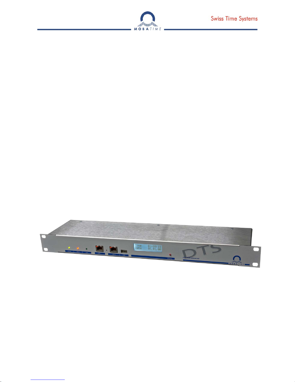
DTS 4138.timeserver
Network – Time Server and Master Clock

© MOBATIME 2 / 104 800870.05
Certification of the Producer
STANDARDS
The DTS 4138.timeserver was developed and produced in accordance with the EU Guidelines:
2006 / 95 / EC
2004 / 108 / EC
96 / 48 / EC
References to the Instruction Manual
1. The information in this Instruction Manual can be changed at any time without notice.
The current version is available for download on www.mobatime.com.
2. The device software is continuously being optimized and supplemented with new options. For this
reason, the newest software version can be obtained from the Mobatime website.
3. This Instruction Manual has been composed with the utmost care, in order to explain all details in
respect of the operation of the product. Should you, nevertheless, have questions or discover errors in
this Manual, please contact us.
3. We do not answer for direct or indirect damages, which could occur, when using this Manual.
4. Please read the instructions carefully and only start setting-up the product, after you have correctly
understood all the information for the installation and operation.
5. The installation must only be carried out by skilled staff.
6. It is prohibited to reproduce, to store in a computer system or to transfer this publication in a way or
another, even part of it. The copyright remains with all the rights with BÜRK MOBATIME GmbH,
D-78026 VS-Schwenningen and MOSER-BAER AG – CH 3454 Sumiswald / SWITZERLAND.

© MOBATIME 3 / 104 800870.05
Overview
1 Safety .......................................................................................................................................................... 6
2 Maintenance ............................................................................................................................................... 8
3 General Information: Introduction ............................................................................................................... 9
4 Displays .................................................................................................................................................... 13
5 Installation ................................................................................................................................................. 15
6 Operation .................................................................................................................................................. 16
7 Updates ..................................................................................................................................................... 57
8 Time administration .................................................................................................................................. 63
9 SNMP ........................................................................................................................................................ 70
10 Power supply alternatives ......................................................................................................................... 74
APPENDIX
A
Connection diagrams ................................................................................................................................ 75
B Time zone table ........................................................................................................................................ 79
C Alarm list ................................................................................................................................................... 82
D Troubleshooting ........................................................................................................................................ 84
E Serial Telegrams ....................................................................................................................................... 86
F Copyright Notice ....................................................................................................................................... 91
G Parameters ............................................................................................................................................... 92
H Technical data ........................................................................................................................................... 96
I Index ......................................................................................................................................................... 99
J Connection table (to fill in) ...................................................................................................................... 101

© MOBATIME 4 / 104 800870.05
Table of contents
1
Safety ............................................................. 6
1.1 Safety instructions ............................................... 6
1.2 Symbols and Signal Words used in this
Instruction Manual ............................................... 6
1.3 Intended Use ....................................................... 6
1.4 Observe operating safety! ................................... 7
1.5 Consider the installation site! .............................. 7
1.6 Please observe the electromagnetic
compatibility! ....................................................... 7
2 Maintenance .................................................. 8
2.1 Troubleshooting: Repairs .................................... 8
2.2 Cleaning .............................................................. 8
2.3 Disposing ............................................................ 8
3 General Information: Introduction .................. 9
3.1 Scope of Delivery ................................................ 9
3.2 Technical Data .................................................... 9
3.3 Device Description in this Manual ....................... 9
3.4 Introduction ......................................................... 9
3.5 Device types ...................................................... 10
3.6 DTS Distributed Time System ........................... 10
3.7 MOBA-NMS - Network Management System ... 11
3.7.1 Overview of the main functions ............................. 11
3.7.2 Device management ............................................. 12
4 Displays ....................................................... 13
4.1 LED displays front side ...................................... 13
4.2 LED indication back side ................................... 13
4.3 Display .............................................................. 14
5 Installation .................................................... 15
5.1 Connections ...................................................... 15
5.2 Boot procedure of the DTS 4138.timeserver ..... 15
5.3 Initial configuration ............................................ 15
5.4 Firmware ........................................................... 15
5.5 Basic settings (factory settings) ......................... 15
6 Operation ..................................................... 16
6.1 General ............................................................. 16
6.1.1 Telnet .................................................................... 16
6.1.2 SSH ....................................................................... 17
6.1.3 Menu structure ...................................................... 17
6.2 MOBA-NMS operation ....................................... 18
6.3 Main menu ........................................................ 19
6.4 Status menu ...................................................... 20
6.4.1 Time information and status .................................. 22
6.4.2 Time source information ........................................ 23
6.5 Configuration menu ........................................... 24
6.5.1 Lines ...................................................................... 25
6.5.2 DCF – output ......................................................... 25
6.5.3 DCF / Pulse / Frequency output ............................ 26
6.5.4 Serial interface ...................................................... 27
6.5.5 IRIG / AFNOR / DCF-FSK Output ......................... 29
6.5.6 NTP slave clocks / time zone server ..................... 30
6.5.7 Time administration ............................................... 31
6.5.8 Time source ........................................................... 32
6.5.9 Time adjustment / Time-keeping ........................... 33
6.5.10 Redundant operation ............................................. 34
6.5.11 NTP server ............................................................ 35
6.5.12 Manual time set / Leap second ............................. 39
6.5.13 Alarms ................................................................... 40
6.5.14 Alarm relay ............................................................ 40
6.5.15 Alarm mask ........................................................... 41
6.5.16 E-mail .................................................................... 42
6.5.17 SNMP traps ........................................................... 44
6.5.18 Alarm input ............................................................ 46
6.5.19 General settings .................................................... 47
6.5.20 Network ................................................................. 48
6.5.21 Services (network services FTP, telnet, SSH...) ... 50
6.5.22 SNMP .................................................................... 51
6.5.23 SNMP V1 / V2c ..................................................... 52
6.5.24 SNMP V3 ............................................................... 53
6.5.25 Time zone selection .............................................. 55
6.6 Maintenance menu ........................................... 56
7 Updates ........................................................ 57
7.1 Updating images with MOBA-NMS ................... 57
7.2 Updating images with FTP ................................ 57
7.3 Updating applications or configurations with
FTP ................................................................... 58
7.4 Updating images via USB ................................. 58
7.5 Updating applications or configurations via
USB ................................................................... 59
7.6 FTP connection ................................................. 60
7.7 SFTP connection .............................................. 60
7.8 SCP connection ................................................ 61
7.9 Save Configuration externally ........................... 61
7.10 Copying Telegram files to the DTS
4138.timeserver ................................................ 62
8 Time administration ...................................... 63
8.1 Concept of time administration .......................... 63
8.2 Time acceptance ............................................... 64
8.3 Time acceptance from an external source
(DCF or GPS) ................................................... 64
8.4 Time acceptance from external AFNOR-A/C,
IRIG-B12x source ............................................. 65
8.5 Time acceptance from NTP .............................. 65
8.6 NTP as backup ................................................. 65
8.7 Time server ....................................................... 65
8.8 Time accuracy, time-keeping ............................ 66
8.9 Leap second ..................................................... 66
8.10 NTP Authentication ........................................... 66
8.10.1 NTP symmetric keys ............................................. 66
8.10.2 NTP Autokey ......................................................... 67
8.11 Redundant operation of 2 DTS
4138.timeservers .............................................. 68
9 SNMP ........................................................... 70
9.1 General ............................................................. 70
9.2 Device configuration with SNMP ....................... 71
9.3 DTS subagent SNMP notification ...................... 71
9.3.1 Startup [dts4138StartUp] ....................................... 71
9.3.2 Shutdown [dts4138Shutdown] ............................... 71
9.3.3 Status changed [dts4138StatusChanged] ............. 72
9.3.4 Configuration changed
[dts4138ConfigChanged] ....................................... 72
9.3.5 Alive Notification [dts4138Alive] ............................ 73
9.3.6 Alarm Notification [dts4138Alarm] ......................... 73
10 Power supply alternatives ............................ 74

© MOBATIME 5 / 104 800870.05
APPENDIX
A
Connection diagrams ................................... 75
A.1 Front connections .............................................. 75
A.2 Connections (rear view) .................................... 76
A.3 Plug-in spring terminals ..................................... 78
A.4 Connection GPS 4500, DCF 450 or GNSS
3000 .................................................................. 78
B Time zone table ........................................... 79
C Alarm list ...................................................... 82
D Troubleshooting ........................................... 84
E Serial Telegrams .......................................... 86
E.1 General ............................................................. 86
E.2 Syntax of the telegram configuration file ........... 87
F Copyright Notice .......................................... 91
G Parameters .................................................. 92
H Technical data .............................................. 96
I Index ............................................................ 99
J Connection table (to fill in) ......................... 101
© MOBATIME BE-800870.05
1 Safety
1.1 Safety instructions
Read this chapter and the entire instruction manual carefully and follow all instructions
listed. This is your assurance for dependable operations and a long life of the device.
Keep this instruction manual in a safe place to have it handy every time you need it.
1.2 Symbols and Signal Words used in this Instruction Manual
Danger!
Please observe this safety message to avoid electrical shock!
There is danger to life!
Warning!
Please observe this safety message to avoid bodily harm and injuries!
Caution!
Please observe this safety message to avoid damages to property and devices!
Notice!
Additional information for the use of the device.
1.3 Intended Use
The DTS 4138.timeserver is a time server for the use in network environments. It can
be synchronized from NTP and be used as NTP server. In addition, it can read the time
from DCF or GPS (e.g. from GPS 4500).
It can operate as master clock for a self-setting IRIG clock line. The DTS 4138 has 1
such line.
For additional functions, see the device descriptions in chapter 3.
The device is designed for 19" racks and intended to be installed in a 19" cabinet.
Operate the device only in installed condition.
!
!
© MOBATIME 7 / 104 800870.05
1.4 Observe operating safety!
Never open the housing of the device! This could cause an electric short or even a
fire, which would damage your device. Do not modify your device!
The device is not intended for use by persons (including children) with limited
physical, sensory, or mental capacities or a lack of experience and/or knowledge.
Keep packaging such as plastic films away from children. There is the risk of
suffocation if misused.
1.5 Consider the installation site!
To avoid any operating problems, keep the device away from moisture and avoid
dust, heat, and direct sunlight. Do not use the device outdoors.
The device is designed for 19" racks and should only be operated installed in a 19"
cabinet.
Danger! Make sure
that you wait before using the device after any transport until the device has
reached the ambient air temperature. Great fluctuations in temperature or
humidity may lead to moisture within the device caused by condensation, which
can cause a short.
1.6 Please observe the electromagnetic compatibility!
This device complies with the requirements of the EMC and the Low-voltage
Directive.
!
Caution!
!
Caution!
!
Caution!
© MOBATIME 8 / 104 800870.05
2 Maintenance
2.1 Troubleshooting: Repairs
Please read carefully Appendix D Troubleshooting if your device does not work
properly.
If you cannot rectify the problems, contact your supplier from whom you have
purchased the device.
Any repairs must be carried out at the manufacturer’s plant.
Disconnect the power supply immediately and contact your supplier if …
liquid has entered your device.
the device does not properly work and you cannot rectify this problem yourself.
2.2 Cleaning
Please make sure that the device remains clean especially in the area of the
connections, the control elements, and the display elements.
Clean your device with a damp cloth only.
Do not use solvents, caustic, or gaseous cleaning substances.
2.3 Disposing
Device
At the end of its lifecycle, do not dispose of your device in the regular household
rubbish. Return your device to your supplier who will dispose of it correctly.
Packaging
Your device is packaged to protect it from damages during transport.
Packaging is made of materials that can be disposed of in an environmentally friendly
manner and properly recycled.

© MOBATIME 9 / 104 800870.05
3 General Information: Introduction
3.1 Scope of Delivery
Please check your delivery for completeness and notify your supplier within 14 days
upon receipt of the shipment if it is incomplete.
The package you received contains:
DTS 4138.timeserver
Mounting set for rack mounting consisting of:
- 4 pcs nuts for 19" housing
- 4 screws M6 for the nuts
- 4 plastic discs for screws M6
Connector set
- 1 * spring terminal 6-pole orange
- 3 * spring terminal 4-pole orange
- 2 * spring terminal 2-pole orange
- 1 * spring terminal 5-pole orange
2 pcs mounting tools with spring terminals
3.2 Technical Data
See Appendix "H Technical data“.
3.3 Device Description in this Manual
This instruction manual is for the master clocks DTS 4138.timeserver and DTS
4139.timeserver. Below both models (DTS 4138 and DTS 4139) will be referred to as
DTS 4138 with the exception of time-keeping.
3.4 Introduction
The DTS 4138.timeserver is a NTP Time Server for use in network environments. It
can be synchronized by DCF or GPS (e.g. from GPS 4500), AFNOR-A/C, IRIG-B
1
and
NTP, and act as a NTP server in a network.
It can be used as a master clock for NTP slave clocks, synchronized via unicast or
multicast with NTP and time zone table.
It is equipped with 2 LAN interfaces for the operation in two independent networks.
In addition, the DTS 4138 provides an IRIG/AFNOR line (available as analog and
digital (current loop and RS422) output), a serial interface for the output of time telegrams as well as an output line for technical pulses (pulse/frequency/DCF).
As the "main“ master clock, the DTS 4138 can synchronize other master clocks or
other equipment with DCF and monitor with 1 alarm input.
The DTS 4138 can send both e-mails and SNMP traps for alerting purposes.
Using MOBA-NMS and SNMP, the DTS 4138 can be fully operated and its
configuration and system status can be requested.
To maintain a redundant time source, two DTS 4138 can be linked by an optical link.
1
With IRIG-B synchronization the date must be set manually once or by another time source (GPS).
© MOBATIME 10 / 104 800870.05
3.5 Device types
Model: Features: Product no.:
DTS 4138.timeserver
According to above description with TCXO
(temperature compensated quartz)
205280
DTS 4138S.timeserver
Like DTS 4138; Siemens version
204760
DTS 4139.timeserver
Like DTS 4138, but with OCXO
(„heated“ quartz)
-
Device descriptions:
Since the only difference between DTS 4138(S) and DTS 4139 is the quartz, no
difference is made on the front plate. It always has DTS 4138.timeserver printed on it.
The precise description is made on the identification label on the back.
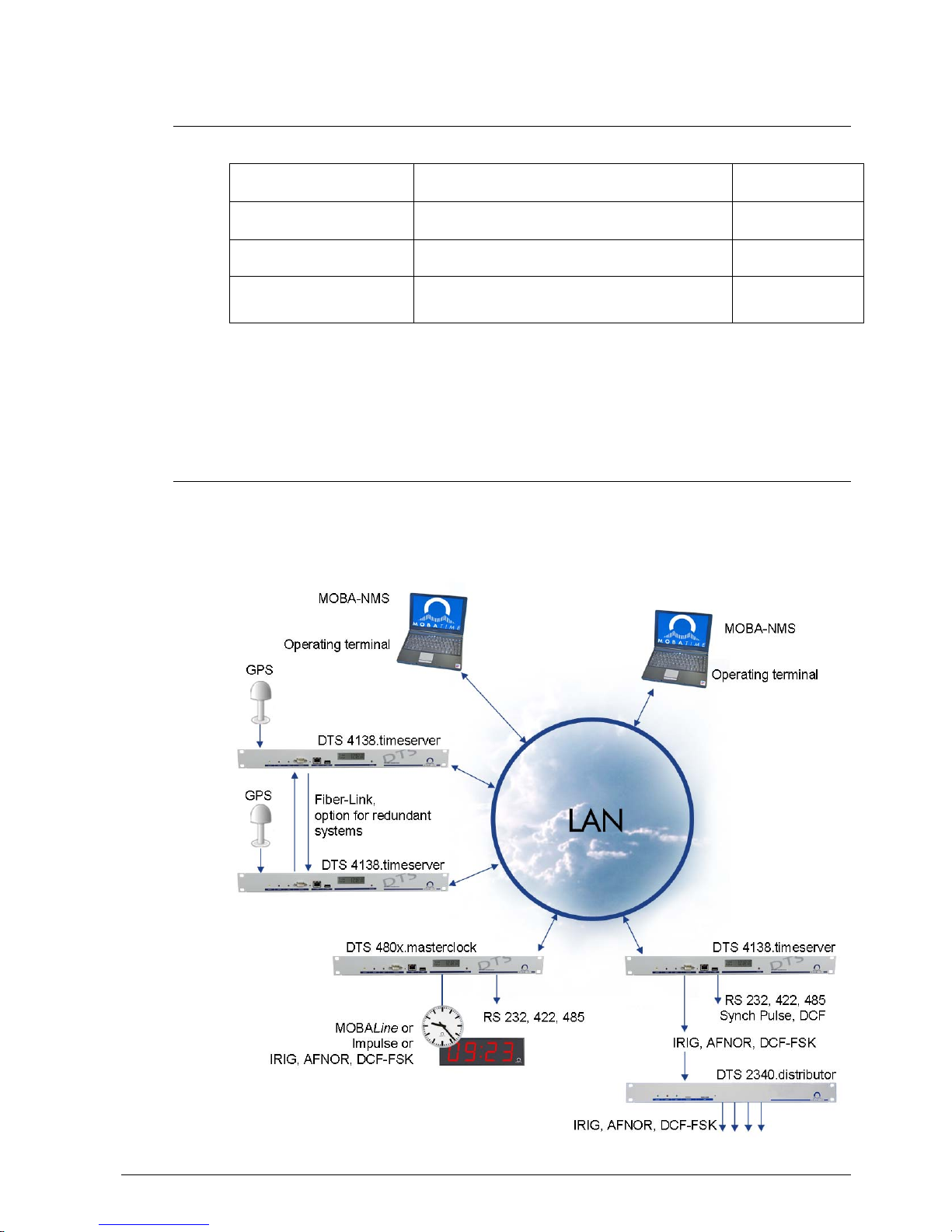
3.6 DTS Distributed Time System
DTS (Distributed Time System) is a system developed by Moser-Baer AG to connect
decentralized master clocks, slave clock lines and time servers. For communication,
standard LAN (Ethernet) is used. The DTS can be centrally operated and monitored.

© MOBATIME 11 / 104 800870.05
3.7 MOBA-NMS - Network Management System
MOBA-NMS is software used for central management and inquiry of state and alarm
information. It supports DTS devices as well as all MOBATime analog and digital
network clocks and can handle a network with more than 1000 devices. This software
provides extensive functions for the configuration, installation, back-up / recovery etc.
especially for DTS devices.
Due to the DTS concept, MOBA-NMS can be installed multiple times in one network.
With different user rights on the device and software level, the configuration abilities of
different users can be set as required.
For DTS devices, all communication is conducted over SNMP V3. The SFTP protocol
is used for broadcasting files.
3.7.1 Overview of the main functions
The main MOBA-NMS functions for DTS devices and network clocks are listed below:
automatic device scan over multicast or IP range
device management using user-defined device groups see chapter „3.7.2 Device
management“
intuitive user interface with input check for the device configuration
status / alarm request and display on the device group level
device firmware update for one or several devices (parallel)
support for device commands, e. g. reset, restart etc.
back-up / recovery of DTS devices
transfer of the whole DTS configuration to another device
user management with different access rights
monitor for NTP and time zone packages
editor for time zone files
online help
etc.

© MOBATIME 12 / 104 800870.05
3.7.2 Device management
All MOBATime network devices are displayed in the so-called device view. Here, the
devices can be grouped according to user-defined criteria. For this, the individual
devices can simply be moved to the according groups and sorted using drag and drop.
There is no limit to the number of groups and sub-groups.
Besides the organizational advantages (easier locating, better
overview), a device group has the following advantages:
commands and device updates can be applied to the whole
group (including sub-groups).
Alarms and errors of included devices are displayed on the
group level.
Complete groups can be moved / sorted among
themselves.
The content of the device view can be saved and opened at a
later time. The created structure and breakdown into groups is
preserved.
© MOBATIME 13 / 104 800870.05
4 Displays
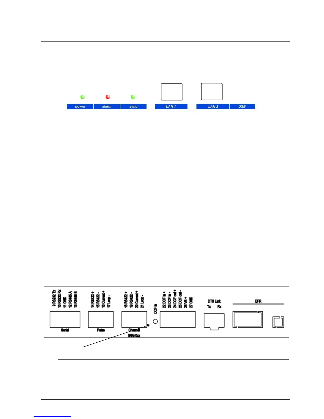
4.1 LED displays front side
Description Color Status Description
Power Green On
Off
Mains or DC power supply is in order
No power supply
Alarm Red On
Off
The alarm relay signalizes an alarm
No active alarms
Sync Green On
Off
DTS 4138 can read the time from a synchronization
source
Synchronization source is not available
LAN 1 control lamps:
Left
Green
Orange
Blinking
Blinking
Network activity
No connection to network
Right Yellow Off
On
10 Mbit
100 Mbit
LAN 2 control lamps:
Left
Green
Orange
Blinking
Blinking
Network activity
No connection to network
Right Yellow Off
On
10 Mbit
100 Mbit
4.2 LED indication back side
Description Color Status Description
DCF in red Blinking DCF (GPS reception), blinking every second time
information from receiver
© MOBATIME 14 / 104 800870.05
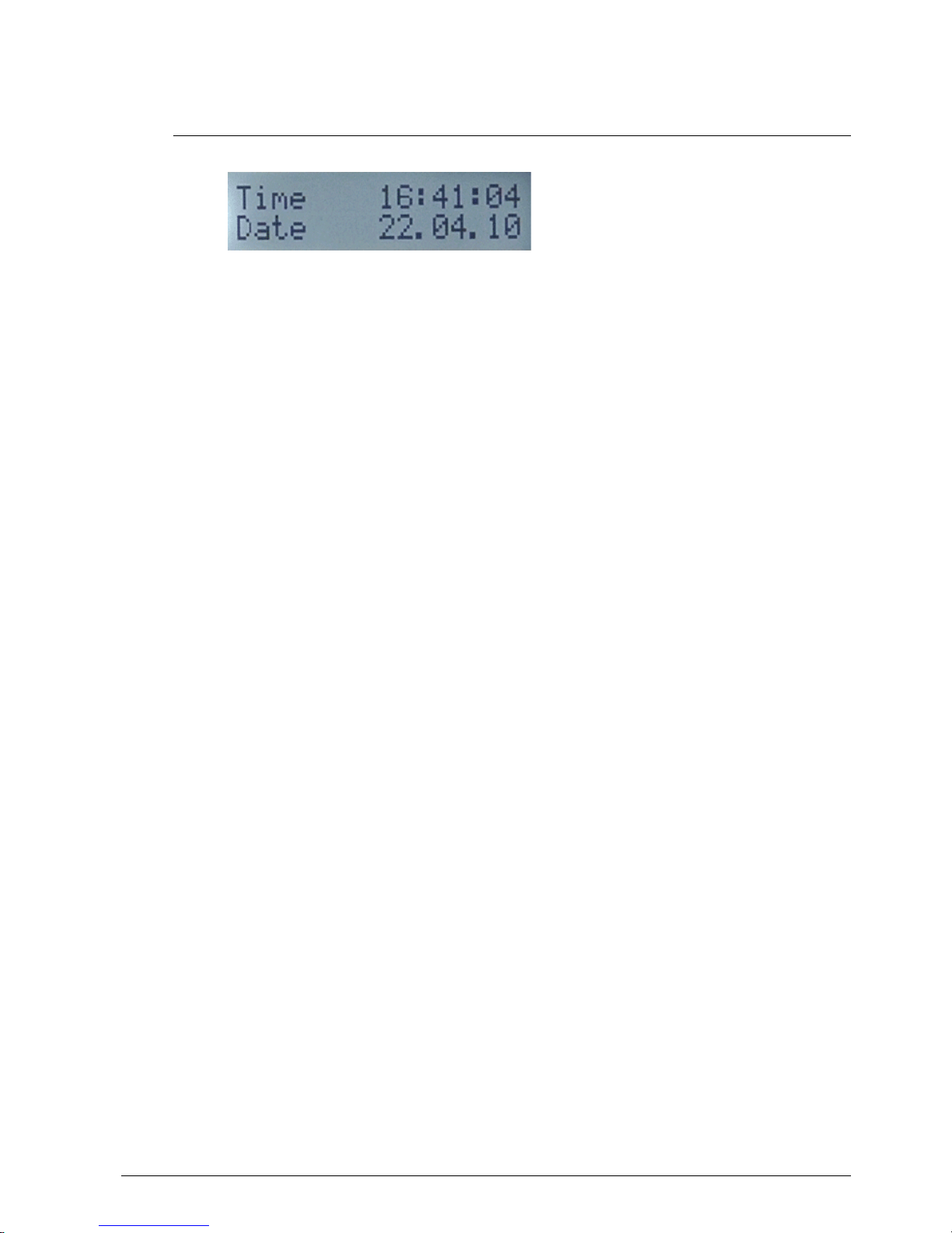
4.3 Display
Display showing the current status of the DTS 4138.
Display of: -Time, date
-Current time source
-Stratum of the DTS 4138, status: Master / Slave
-Software version
-IPv4 address LAN 1
-IPv4 address LAN 2
-IPv6 address LAN 1
-IPv6 address LAN 2
-Alarm summary
-Current alarms
The display can be operated by means of the corresponding “Display“ button:
First press the button briefly: Switch on the background light
Other buttons to press briefly: Scroll through all displays
Press button longer (>3 sec): Change to default display (time and date)
The display changes after approx. 3 min without pressing the button for the default
display and the background light goes off.
If a USB stick has been plugged in, it will be displayed. If only telegram files should be
copied or the network settings should be changed, this can be activated directly with
the button. (Press the button until the copy process starts).

© MOBATIME 15 / 104 800870.05
5 Installation
5.1 Connections
The connections are specified in Appendix “A Connection diagrams“.
Only connect the designated devices to the various inputs and outputs.
5.2 Boot procedure of the DTS 4138.timeserver
The normal booting time of the DTS 4138 is approx. 60 sec. with pre-set IP or with
DHCP. The booting procedure of the operating system is displayed on the serial
console. After that, the text "starting" appears on the display (during the booting
procedure the display is dark and empty). Without connection to a DHCP server, the
first start up can take up to 75 seconds. After that, the DHCP option must be set to "off"
in the network configuration.
The display “starting“ remains until the time of output to the lines.
The duration, depending on the configuration, is 5-30 sec.
5.3 Initial configuration
Per default, the LAN 1 interface is configured with DHCP on. After booting in a network
with DHCP server, the received IP address can be displayed.
The LAN 2 interface is configured with the following static settings per default:
IP 192.168.1.5, Subnet 255.255.255.0, Gateway 192.168.1.1
If these possibilities do not work out for the initial configuration, the network
configuration can be modified using a USB stick. For this purpose, a text file named
DTS4138NW.conf is created and filled with the corresponding parameters (not all
parameters are required):
IP1:192.168.1.3
SUB1:255.255.255.0
GW1:192.168.1.1
IP2:10.0.0.7
SUB2:255.255.240.0
GW2:10.0.0.1
The insertion of the USB stick is displayed. For taking over the network settings, press
the button until the normal time display reappears.
5.4 Firmware
It is recommended to install the current firmware on your device prior to the definite
commissioning. The current firmware can be found under www.mobatime.com
Customer Data Product Ressources Time Server.
5.5 Basic settings (factory settings)
The basic settings can be found in the table in Appendix “G Parameters”.
© MOBATIME 16 / 104 800870.05
6 Operation
6.1 General
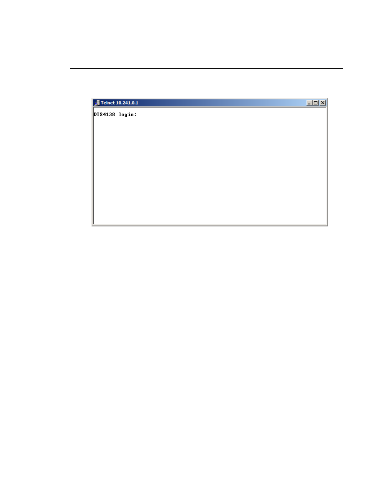
Operation occurs via a terminal menu or SNMP. SNMP operation is explained in
chapter “9 SNMP“. Operation with the terminal menu takes place either via Telnet or
SSH. After a connection has been set up, the login screen is displayed:
To start the menu, dts must be logged in as user. The standard password is dts.
(Changing the password see chapter “6.5.19 General settings“).
Only one menu can be open at any time. The first menu started has priority. The menu
is automatically closed after 15 min. without operation, and any possible connection via
Telnet or SSH is interrupted.
Backspace:
Backspace must be set to "delete“ with the serial terminal:
For example, for HyperTerminal under "File Properties Settings - Backspace
sends DEL" must be selected.
Local echo:
Some terminals (serial or Telnet) do not display the characters entered. It is, therefore,
necessary to switch on the "local echo" in the terminal.
6.1.1 Telnet
Windows 98, 2000, XP, Vista, Windows 7: Start Run telnet [IP-address]
Password: by default, no password
NetTerm (Shareware)
Linux: Start console and enter “telnet [IP-address]
© MOBATIME 17 / 104 800870.05
6.1.2 SSH
Windows 98, 2000, XP, Vista, Windows 7: e.g. with Putty
Linux: Start console and enter “ssh dts@[IP address]“
6.1.3 Menu structure
The current menu is always displayed in the menu title. The menu options show all
the selectable menu functions. Provided the menu item is not a further menu, the set
parameters are displayed. Error messages (e.g. invalid entries) or additional
information to the selected menu items are displayed in the response line. The input
line shows the current input values or options possible. The status line only appears,
when an information has to be displayed, e.g. "An alarm is active".
All entries must be completed with ENTER (Return) (e.g. also ESC).
The menu window can always be exited with Ctrl-C (incl. termination of the Telnet and
SSH connection).
The desired menu can be selected with the relevant number.
The numbers 98 and 99 are always used identically:
With 98, the settings entered are saved and the menu exited. Depending on the
change, the DTS 4138, or only partial functions, are rebooted.
With 99, all changes to the menu are reversed and the menu exited.
In the menus where data cannot be saved (command 98), the menu is only exited
with 99, but any changes are not saved.
The current menu is updated, without any further entry, with ENTER.
menu title
menu options
input line (prompt)
response line
parameters
status line
© MOBATIME 18 / 104 800870.05
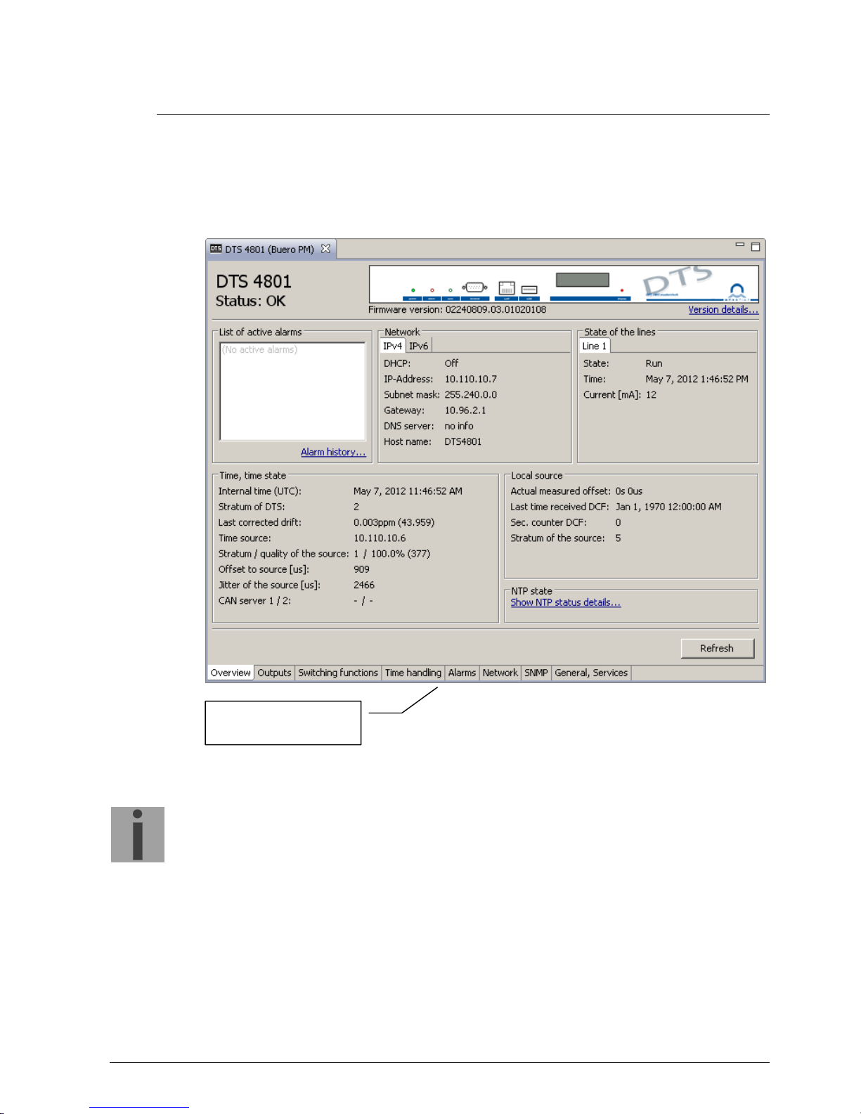
6.2 MOBA-NMS operation
For the configuration of DTS devices via GUI, MOBA-NMS (see chapter „3.7 MOBANMS - Network Management System“) can be used. All configuration possibilities are
subordinated in different configuration pages (called „tabs“). These tabs are connected
to the terminal menu and designated accordingly. Example: The terminal menu
„Configuration Alarms“ can be found in MOBA-NMS under the tab „Alarms“.
Configuration example of a DTS 4801.masterclock:
For further details on the general MOBA-NMS operation, check the integrated online
help (menu „Help Show help“).
Important:
To enable the communication between MOBA-NMS and the DTS devices,
SNMP must be activated! Set terminal menu „Configuration SNMP
SNMP Mode“ to „on“. SNMP is activated by default.
configuration pages
(
tabs)
© MOBATIME 19 / 104 800870.05
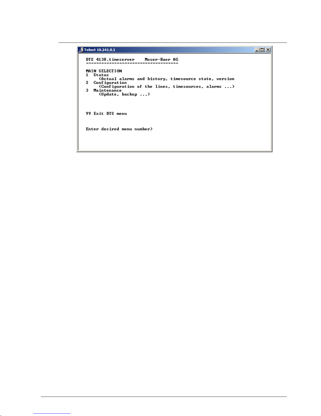
6.3 Main menu
Menus:
Status: Display of various information regarding operation and environment
See chapter “6.4 Status menu“
Configuration: Configuration of the DTS 4138
See chapter “6.5 Configuration menu “
Maintenance: Software update, backup and restore
See chapter “6.6 Maintenance menu“

© MOBATIME 20 / 104 800870.05
6.4 Status menu
The status menu consists of 2 pages.
Status menu page 1:
The menu shows various information on the current operating status.
1. Requesting alarm status, display of all the DTS 4138 active errors.
Display of the DTS 4138 alarms (64) on 4 pages. The ALARM DETAIL menu
pages can be scrolled through with ENTER. Active alarms are displayed with a *.
The ALARM DETAIL menu page can be exited with 99. All DTS 4138 active
alarms are displayed, masking (e-mail, traps, relay) only occurs later.
2. Alarm history display.
Display of the DTS 4138 alarm record, newest alarm first. The ALARM RECORD
menu pages can be scrolled through with ENTER. The ALARM RECORD menu
page can be exited with ESC.
Max. length of error report: 240 messages.
3. Current time and status display. See chapter "6.4.1 Time information and status"
4. Time source information display. See chapter "6.4.2 Time source information"
5. Power supply information (current, voltage) display.
6. Current network configuration display. With ENTER, a second page can be
displayed with network information.
7. DTS 4138 system information display (internal status, regulation voltage of the
quartz..). This information is for support purposes only.
8. Product information like serial number, firmware version etc.
9. All respective software versions of the DTS 4138 components.
© MOBATIME 21 / 104 800870.05
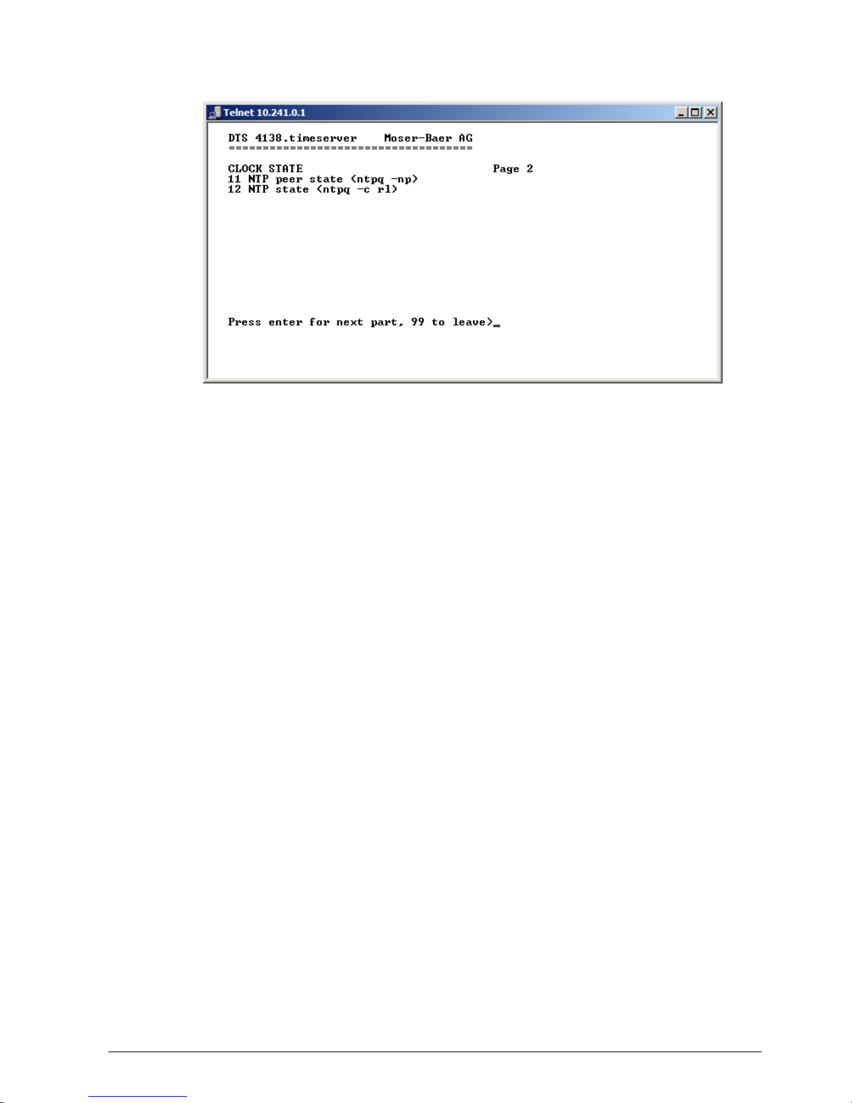
Status menu page 2:
Display of information with regard to the internal state of the NTP server.
© MOBATIME 22 / 104 800870.05
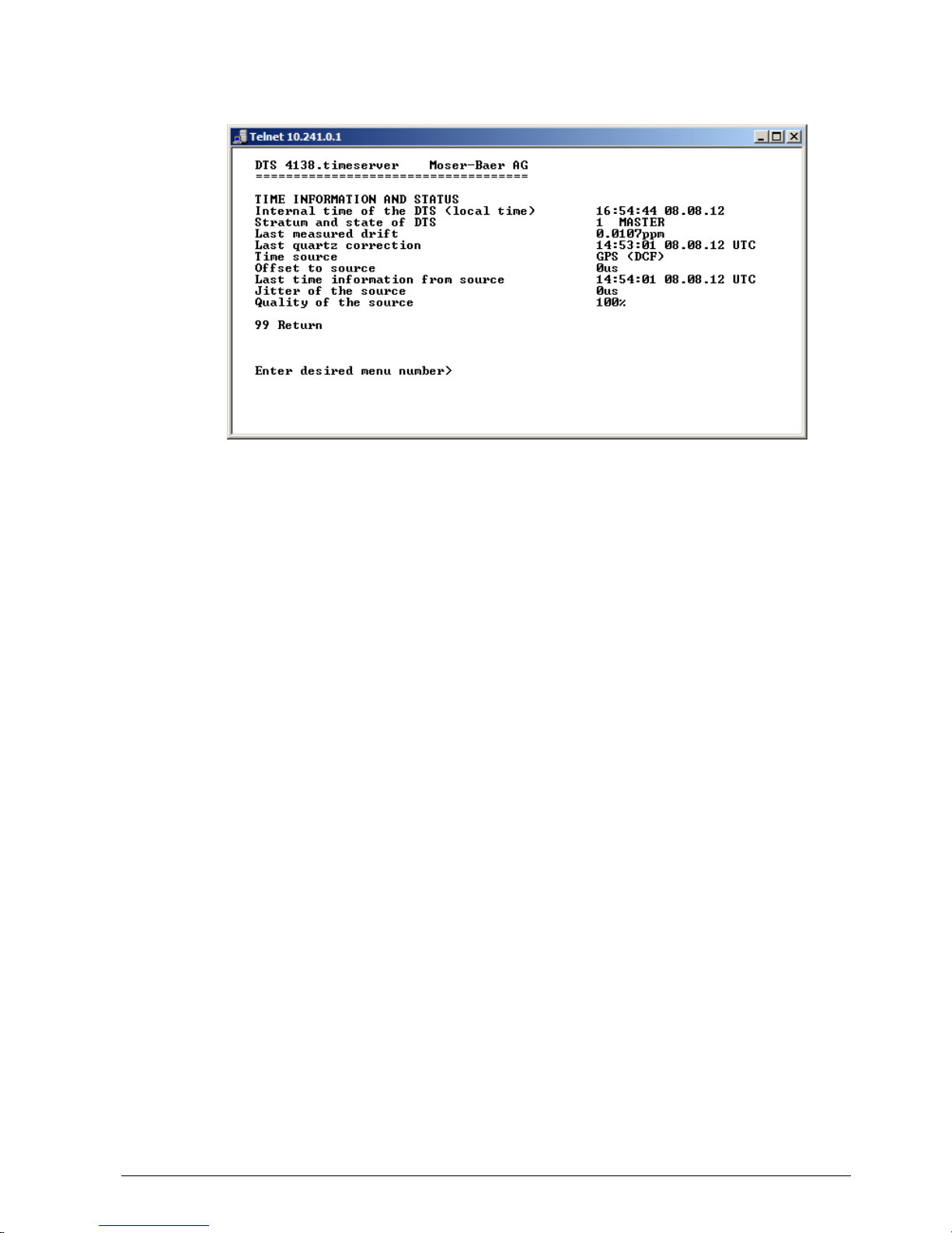
6.4.1 Time information and status
- Internal time of the DTS: local time
- Stratum and status of the DTS: current stratum,
status: MASTER, SLAVE, not defined
- Last measured drift: drift before the last quartz correction
- Last quartz correction: time of the last quartz correction
- Time source: current time source
- Offset to source: offset to source (source – system time)
- Last time info. from source: time of the last information from source
- Jitter of the source: current jitter
- Quality of the source: quality of the source
© MOBATIME 23 / 104 800870.05
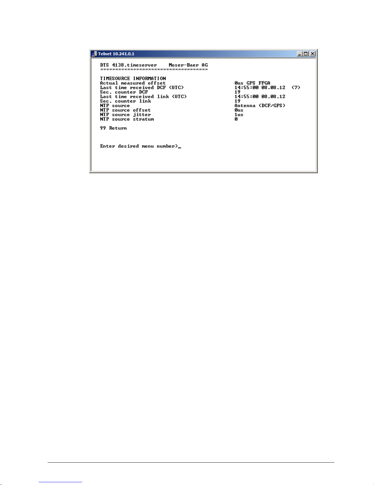
6.4.2 Time source information
- Currently measured offset: last measured offset with source info and type of
measurement (only needed for Moser-Baer
support).
- Last time received DCF: last time received from DCF source
In (): Information about number of available
satellites (only for GPS 4500 and GNSS 3000).
For DCF, this value is random.
- Sec. counter DCF: the counter is incremented by 1 with each DCF
pulse. For the minute marker, the counter is set
to 0.
- Last time received link: last time received from DTS Link
- Sec. counter link: analogue sec. counter DCF
- NTP – Source: current time source (system-peer) of the NTP
Server
Antenna = DCF or GPS
- NTP source offset: current offset of the NTP Server
- NTP source jitter: jitter of the current source
- NTP source stratum: stratum of the current source
© MOBATIME 24 / 104 800870.05
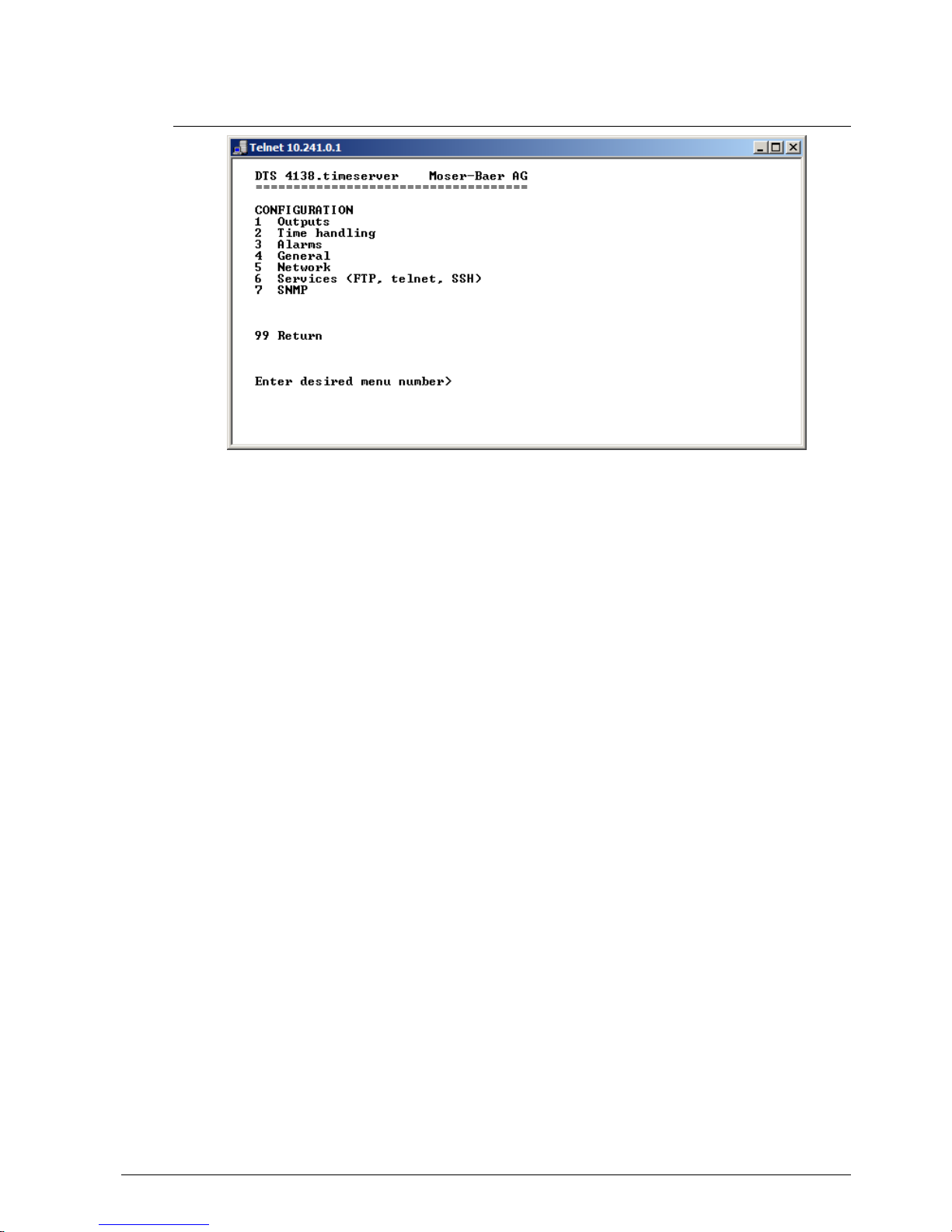
6.5 Configuration menu
Configuring the DTS 4138 through various submenus:
1. Configuring the lines / outputs (DCF/pulse/frequency, serial interfaces,
IRIG/AFNOR/DCF-FSK and NTP slave clock line) See chapter "6.5.1 Lines"
2. Configuring the time source, time-keeping etc.
See chapter "6.5.7 Time administration"
3. Alarm settings (alarm relay, e-mail, SNMP)
See chapter "6.5.13 Alarm"
4. General settings of the DTS 4138 (language, time zone for alarms and display,
password for menu, power supply monitoring...)
See chapter "6.5.19 General settings"
5. Network Settings
See chapter "6.5.20 Network"
6. Services (switching network services such as FTP, Telnet, SSH on or off)
See chapter "6.5.21 Services (network services FTP, telnet, SSH...)"
7. SNMP Configuration for GET/PUT.
See chapter "6.5.22 SNMP" (Traps are dealt with in menu ’2. Configuration’ ’3.
Alarms’ ’3. Traps’. See also chapter “6.5.17 SNMP traps“)
© MOBATIME 25 / 104 800870.05
6.5.1 Lines
Under lines, settings can be undertaken for the following functions:
1 DCF - Output see chapter 6.5.2
2 DCF / Pulse / Frequency output see chapter 6.5.3
3 Serial Interface see chapter 6.5.4
4 IRIG / AFNOR / DCF-FSK output see chapter 6.5.5
5 NTP slave clocks / time zone server see chapter 6.5.6
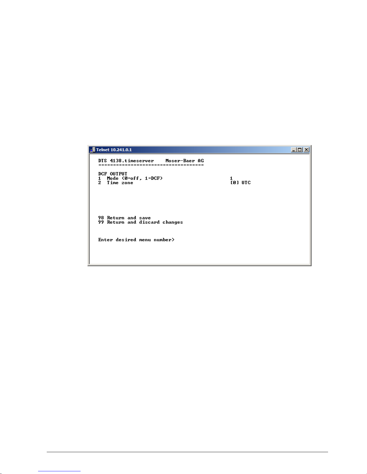
6.5.2 DCF – output
The DTS 4138 is equipped with one DCF output line.
This line is available on the electrical current loop DCF output.
1. Select line function: off or DCF on
2. Select time zone see chapter 6.5.25 Time zone selection.
© MOBATIME 26 / 104 800870.05
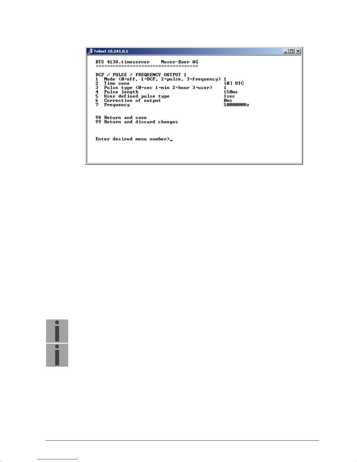
6.5.3 DCF / Pulse / Frequency output
1. Select line function: Line switched off, line DCF output, line pulse output, line
frequency output
2. Select time zone see chapter 6.5.25 Time zone selection.
3. Select pulse mode: every second, minute, hour or user-defined.
(Only active with the pulse output function)
4. Select pulse length in ms (1-500ms)
(Only active with the pulse output function)
5. User-defined pulse interval (1-3600 sec) only active with pulse type 3 (=user) (the
value is also only then displayed). The pulse always occurs after a multiple of the
pulse interval from the 0 second in the 0 minute, e.g.:
– Pulse interval 960 sec. (16 min.)
Pulse occurs: 00:00:00, 00:16:00, 00:32:00, 00:48:00, 01:00:00, 01:16:00 ...
– Pulse interval 25sec
Pulse occurs: 00:00:00, 00:00:25, 00:00:50, 00:01:15, 00:01:40, 00:02:05 ...
... 00:59:35, 01:00:00, 01:00:25 ...
6. Output correction (-500ms...+500ms)
7. Frequency (1…5000 Hz)
Important:
Only frequencies which fulfill the following requirements are to be used,
otherwise, phase shifts occur:
20'000'000 / frequency = whole number value
Important:
Frequencies above 2 MHz are not sent out as a square-wave signal
anymore.
© MOBATIME 27 / 104 800870.05
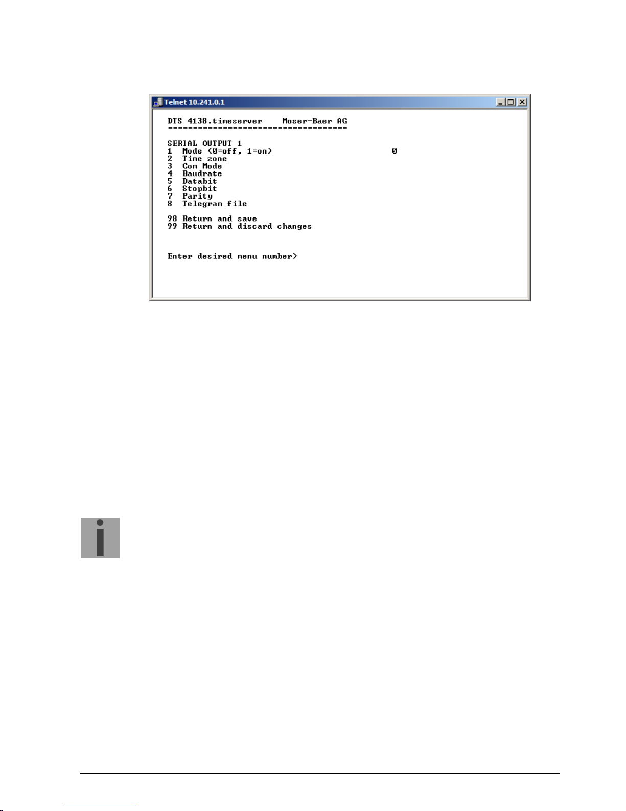
6.5.4 Serial interface
Serial telegram output via RS232, RS422 or RS485.
1. Select mode: Line switched off / on
2. Select time zone see chapter 6.5.25 Time zone selection.
3. Com mode:
1 = send RS 232 (receive is not enabled)
2 = send and receive RS232
3 = send and receive RS485
4 = send RS 422 (receive is not enabled)
4. Baudrate: 300, 600, 1200, 2400, 4800, 9600, 19200, 38400
5. Data bit: 7 or 8
6. Stop bit: 1 or 2
7. Parity: none, even, odd
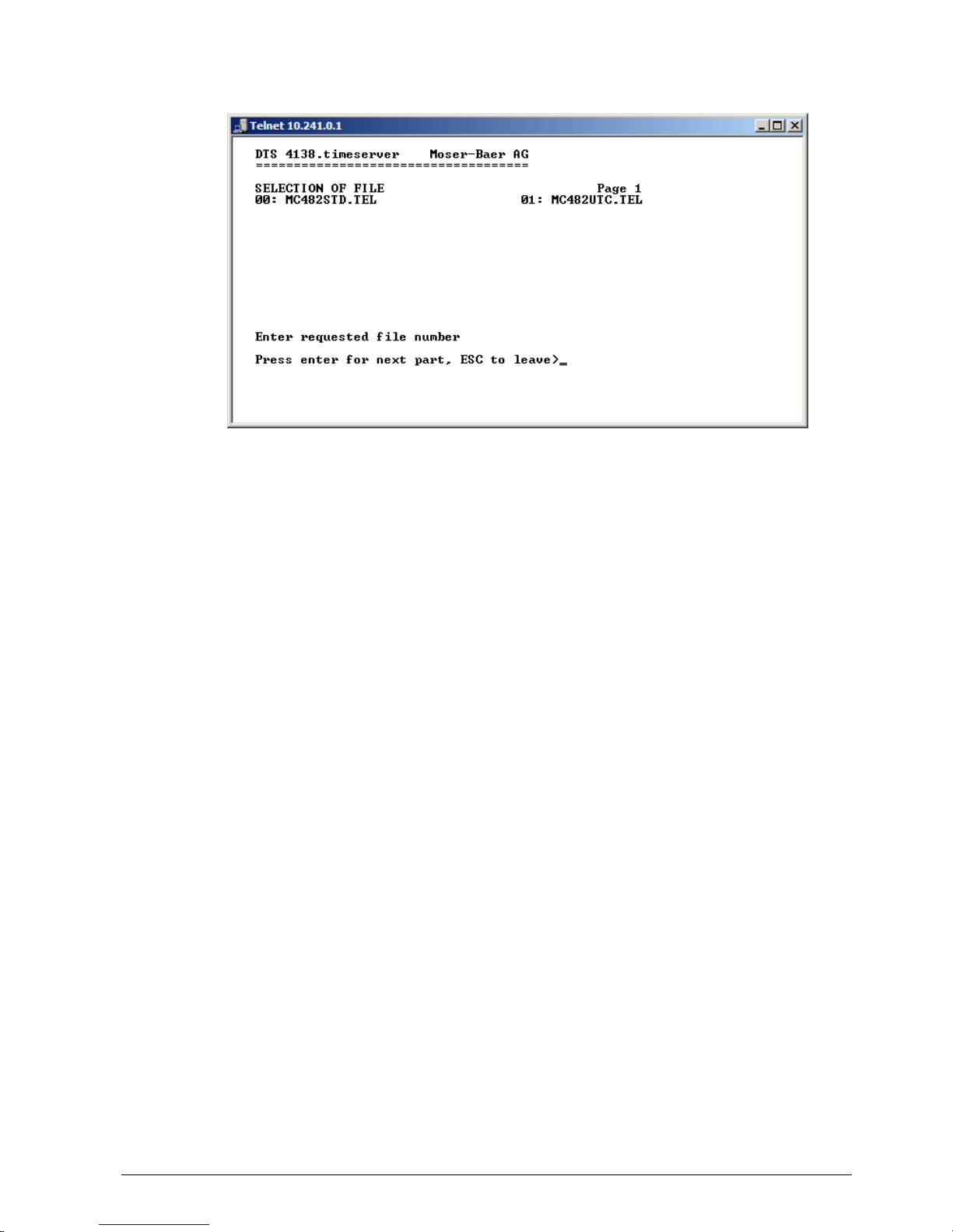
8. Selecting telegram file changes to the menu “SELECTION OF FILE“
Notice:
To set the parameters, the line type has to be selected first.
The description of the telegram function and the telegram file can be found in Appendix
E Serial Telegrams.
© MOBATIME 28 / 104 800870.05
Selection of the telegram file:
The copy procedure of telegram files is explained in chapter "7.10 Copying Telegram
files to the DTS 4138.timeserver“.
© MOBATIME 29 / 104 800870.05
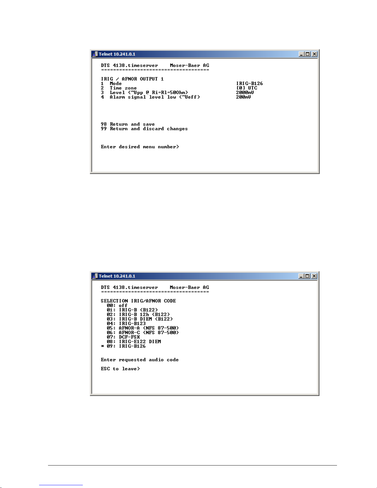
6.5.5 IRIG / AFNOR / DCF-FSK Output
1. Select mode: see picture below
2. Select time zone see chapter 6.5.25 Time zone selection.
3. Configuration of the output voltage level (100 – 5500 mV):
The defined voltage corresponds to the expected output amplitude when power
matching (impedance matching) with a load of 50 Ohms is fulfilled. The output
voltage is not controlled, resp. it is not adjusted in case of a load change.
4. Configuration of the output voltage level supervision (0 – 2000 mV):
When the output voltage falls below the defined voltage level, an alarm is released.
Selection line function:
© MOBATIME 30 / 104 800870.05
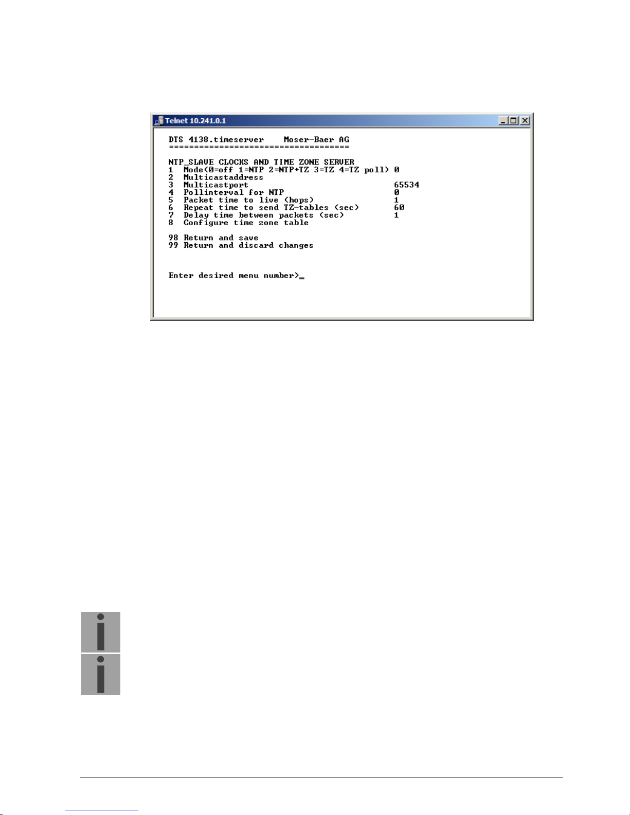
6.5.6 NTP slave clocks / time zone server
NTP slave clock line for operating slave clocks on the LAN (Ethernet). With this clock
line, a world time function can be realized.
1. Mode of clock line: 0 = off, 1 = Send NTP multicast, 2 = Send NTP multicast and
time zone table, 3 = Send time zone table, 4 = Time zones on request, 5 (only for
maintenance) = Send an empty time zone table and return to previous mode.
2. Multicast adress for NTP and time zone server: 239.192.54.x
Group address: x = 1-15 for MOBATIME devices, e.g. NCI, SEN 40.
3. Multicast port for Time zone server (enter an arbitrary value, empty is not allowed!
Value e.g.: 65534). The port is also needed for requesting time zone entries
(mode 4).
4. Poll-interval for NTP Multicast in 2^poll-values in seconds (range: 1 – 16).
E.g. poll-value = 2 interval: 2
2
= 4 sec., poll-value = 5 interval: 25 = 32 sec.
For redundant Multicast time servers see remark next page.
5. Packet time to Live (TTL) for NTP- and time-zone-Multicast-packets in hops.
(Number of Routers in a network to transfer the packets through; for simple network
without routing, enter value "1", for 1 Router enter "2").
6. Repeat time to send time zone table: 10 – 86400 sec.
7. Delay time between the sending of the individual time zone entries (one entry per
Multicast packet) of the table: 1 – 60 sec.
8. Configuration of individual time zone entries. Displays menu “TIME ZONE TABLE“.
Notice:
Changes of multicast address, poll interval and TLL lead to a restart of
the NTP server.
Notice:
For the operation of a multicast communication (NTP and Time Zone
Server) the configuration of a gateway is required (see chapter “6.5.20
Network”). The gateway can be set manually or by using DHCP.
If there’s no gateway available, it’s possiible to set the own IP as gateway.

© MOBATIME 31 / 104 800870.05
Notice:
Redundant Multicast time server:
If two NTP servers in the same network should send NTP with the same
Multicast IP address (redundancy), then the first time server has to be
configured with a small pollinterval (e.g. 2 4 sec.) and second time
server with a large pollinterval (min. 100 x larger, e.g. 9 512 seconds).
As long as the first time server is sending NTP Multicast packets, the
packets from second time server are ignored. This configuration is
needed, to reach a defined situation for the end devices (the DTS with the
more frequently NTP send rate gets higher priority for time reception).
Time zone table for the NTP slave clock line:
Display of all time zone entries (15) of time zone servers for NTP slave clock lines.
Choose a zone number to change selected zone.
Time zone selection see chapter “6.5.25 Time zone selection“.
The page can be exited with 99. Changes are first stored or reset on the overlying
menu page.
6.5.7 Time administration
Under time administration, settings can be undertaken for the following functions:
Time source configuration see chapter “6.5.8 Time source “
Time adjustment configuration see chapter “6.5.9 Time
adjustment / Time-
keeping“
Redundant operation see chapter “6.5.10 Redundant operation“
NTP Server see chapter "6.5.11 NTP server"
For setting the time manually see chapter “6.5.12 Manual time set / Leap second“

© MOBATIME 32 / 104 800870.05
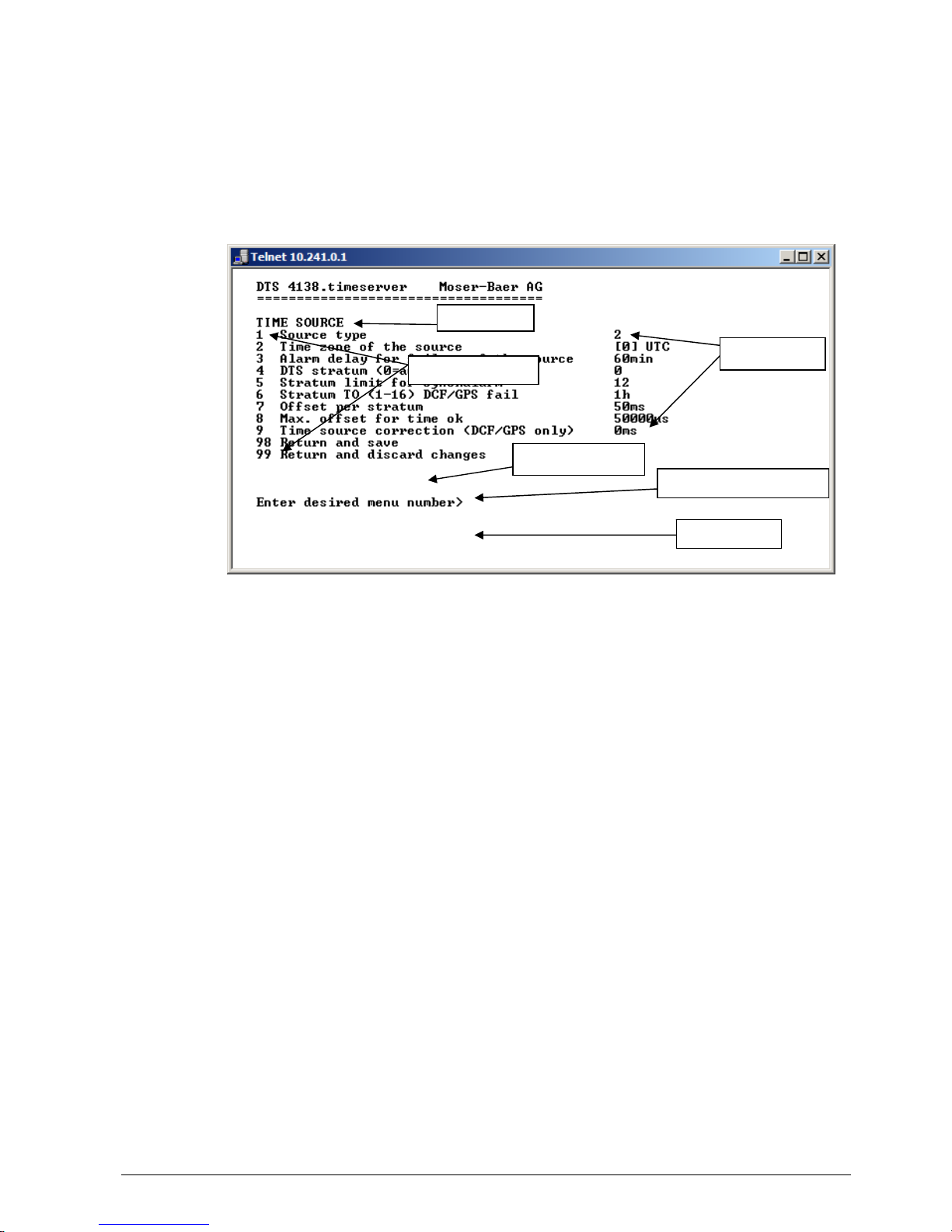
6.5.8 Time source
Time source configuration.
1. Type of time source: 0=none, 1=DCF low quality, 2=GPS-DCF high quality,
3=NTP, 4=AFNOR-A/C or IRIG-B 12X
2. Time zone of the source: see chapter 6.5.25 Time zone selection.
3. Alarm delay at failure of time source (minutes):
0 = off, 1-2'160min, default = 0
Error: “loss of time source TO” resp. “loss of local source”
in redundant mode as slave
4. DTS stratum: 0=Stratum is automatically calculated according to
the time source.
1-15= Stratum DTS 4138 is set by means of the
description in the table in chapter “Fehler! Verweisquelle
konnte nicht gefunden werden. Time acceptance
from an external source (DCF or GPS)”
5. Stratum limits for alarm: Limits for alarm “Time source stratum lost“ (1-16)
6. Stratum TO (Timeout):
Duration of stratum change 1 to 16 in the case of time loss (1-999h),
e.g. 24 hrs stratum counts up from 1 to 16 within 24 hrs.
Default value: 12h
7. Offset per Stratum in ms (0 – 40’000 ms). Stratum is calculated with this value
when time is received again:
Offset/Stratum = 30 ms, offset of the time source 150 ms Stratum = 5
8. Max. offset for time source to set valid time in s at start up.
(0-1’000’000s)
9. Time source correction (only for DCF), +/-60'000ms
For description of time source see chapter “8 Time administration“

© MOBATIME 33 / 104 800870.05
6.5.9 Time adjustment / Time-keeping
1. Adjust mode: 0=time is slowly adjusted
1=time is set immediately
2. Maximum catch up speed in ns/s (0-10'000’000).
3. Quartz type: Standard=0 (0-255)
4. Synch. only offset: 0=off
100-5000ms=Limits as from which time is no longer
accepted Alarm “Syn only diff too great“
5. RTC mode 0=RTC deactivated
1=ON, with initial time set, independent of the mode (1)
2=ON
Notice:
Explanation to the RTC mode:
RTC mode 0:
After startup of the device the system time starts at 00:00. First of all, the
device has to receive the time from its time source. The time adjust
happens according to the
"1 Adjust mode".
RTC mode 1:
The internal real time clock (RTC) is activated. After startup of the device
the system time is set with the RTC time.
The first takeover of the time from the time source happens in one step,
independent from the Adjust mode (1) setting.
RTC mode 2:
The internal real time clock (RTC) is activated. After startup of the device
the system time is set with the RTC time.
The time takeover from the time source happens according to the Adjust
mode (1).
Adjust mode = 0: time is slowly adjusted
Adjust mode = 1: time is set immediately
Important!
For the redundant operation, the RTC mode should be switched off!
For a description of time-keeping see chapter “8 Time administration“

© MOBATIME 34 / 104 800870.05
6.5.10 Redundant operation
1. Mode: 0=single operation
1=operation in combination with a 2
nd
DTS 4138
2=2 LAN Mode: redundant operation of 2 DTS 4138 without
LAN connection of the 2 devices.
2. Stratum limit to switch from slave to master. Standard 16 (1-16)
3. Max. offset of slaves to the slave time source for triggering the alarm “Offset
Source (Slave)“ (0-5'000'000us)
4. Port for LAN-Link. default 14338
5. IP address of the 2
nd
DTS 4138. Only required if the optical link is not working.
Format 10.241.23.99
ENTER without entering an address will delete the entry.
6. Manual change from slave to master. The command is effected immediately.
Saving with ’98’ is not required when exiting the menu.
For a description of redundant operation, see chapter “8.11 Redundant operation of 2
DTS 4138.timeservers“
Important!
In redundant operation, no additional NTP servers may be configured as
backup sources.
Important!
For the redundant operation, the RTC mode should be switched off!

© MOBATIME 35 / 104 800870.05
6.5.11 NTP server
NTP can run as server or combined as server/client. To run NTP as source (NTP as
client), in the menu ’2. Configuration’ ’2. Time handling’ ’1. Time source setting'
’1. Source type' choose NTP and set at least one server. If NTP server is
configured, but NTP is not indicated as time source, NTP only runs as backup time
source (redundancy) to the actual time source.
The exact behavior of NTP time sources is described in chapter “8.5 Time acceptance
from NTP“.
Further two multicast or broadcast addresses can be configured.
1.-4. Summary about configured NTP – time sources. Select to configure.
5.-6. Summary about configured NTP – broadcast addresses. Select to configure.
7. NTP Authentication: Changes to the menu “NTP AUTHENTICATION"
Information about a multicast – address, configured for NTP slave clocks.

© MOBATIME 36 / 104 800870.05
Configuration of the individual server/peer address is as follows:
1. Insert time sources (IP address or name, e.g. “ntp.metas.ch”)
ENTER without entry of an address will delete value.
2.-3. Configurations of Minpoll and Maxpoll: Inquiry interval 2^poll value in seconds.
0 = automatically
e.g. poll value=2 intervall 2: 2
2
= 4sec., poll value=5 intervall 5: 25 = 32sec.
Range of poll values (exponent): 1 – 16
To get an exact synchronization it’s better to limit Maxpoll to 6 (64 sec.).
4. Set type of NTP inquiry: server or peer
5. Preferred source: on or off
6. Authentication key: off, key number, autokey
Notice:
All changes lead to a restart of the NTP server!
Notice:
If NTP only runs as a backup (source DCF or GPS), no NTP source
should be indicated as prefer!
Notice:
Maxpoll should not be selected under 4 (16 sec), as otherwise, internal
trimmung may be inaccurate.
Maxpoll and Minpoll on automatic can lead to insufficient synchronization
accuracy. The specified accuracies were measured with Minpoll = 3 and
Maxpoll = 6.
The configuration server should be used whenever possible.

© MOBATIME 37 / 104 800870.05
Configuration of the Multi- / Broadcast address is as follows:
1. IP address of the destination network (multicast or broadcast).
ENTER without entering an address will delete the entry.
2. Interval for sending out the NTP information in seconds.
The interval is rounded after the entry to NTP standard, which only permits values
of format 2
x
: 1,2,4,8,16,32,64... Maximum 65536 seconds.
3. TTL (time to live) in hops. Only required for multicast.
Number of routers over which the multicast packet should be transmitted: for
simple networks without a router - enter 1, for 1 router - enter value 2.
4. Authentication key: off, key number, autokey
Notice:
All changes lead to a restart of the NTP server.

© MOBATIME 38 / 104 800870.05
Configuration of the NTP authentication:
The NTP authentication is described in chapter "8.10 NTP Authentication“.
1. Import keys (from /ram directory)
The file ntp.keys must first be copied into the directory /ram.
Notice:
The file must be named exactly in this way and written entirely in small
letters.
2. Export keys (to /ram directory)
The current ntp.keys file is written in the directory /ram.
3. Select the trusted keys separated by space
4. Select the request key
5. Select the control key
6. Set the auto key password
7. Execute for auto key commands:
gen_iff generate the IFF certificate
gen_gq generate the GQ certificate
gen_mv* generate the MV certificate
gen_all * generate all (IFF,GQ,MV) certificates
gen_client generate the client certificate
update_server update the server certificate
update_client update the client certificate
export_iff export the IFF server certificate to /ram. Parameter password
of the client
export_gq export the GQ server certificate to /ram.
export_mv* export the MV server certificate to /ram.
import_iff import the IFF server certificate from /ram.
import_gq import the GQ server certificate from /ram.
import_mv* import the MV server certificate from /ram.
clear_ram delete the certificates in /ram
clear_keys delete the certificates in the NTP key directory
Example: export_iff myPassword exports the IFF client certificate to /ram.
*MV schema is currently not available

© MOBATIME 39 / 104 800870.05
6.5.12 Manual time set / Leap second
1. Set UTC time in the format “hh:mm:ss DD.MM.YY“.
Time is set with ENTER!
2. Correct time in ms (- = backwards). Range: +/-10'000ms
Time is set with ENTER!
3. Leap second mode:
0 off
1 Additional second will be inserted at entered time
Is set to 0=off after inserting the leap second.
-1 Second will be left out at entered time
Is set to 0=off after inserting the leap second.
2 Recognize leap second automatically. Only possible with a source with leap
second announcement!
4. Set UTC time of leap second in format: “hh:mm:ss DD.MM.YY“
For a description of the leap second, see chapter “8.9 Leap second“

© MOBATIME 40 / 104 800870.05
6.5.13 Alarms
Under alarms, settings can be undertaken for the following functions:
Alarm relay see chapter 6.5.14
E-mail see chapter 6.5.16
SNMP traps see chapter 6.5.17
Alarm input see chapter 6.5.18
6.5.14 Alarm relay
1. Alarm mask for relay (see chapter "6.5.15 Alarm mask")

© MOBATIME 41 / 104 800870.05
6.5.15 Alarm mask
Display of all the DTS 4138 alarms (64) on 4 pages. Pages can be scrolled through
with ENTER.
An alarm on the current page can be switched on or off by entering an error number.
The page can be exited with 99. The modifications will be saved or restored one menu
level higher in “ALARM CONFIGURATION“. All Alarms with “error bitxx“ are not yet
used.
A description of individual errors can be found in appendix "C Alarm list".
The alarm masks for the various applications (E-mail, SNMP, SNMP Traps, alarm
relay) can differ.

© MOBATIME 42 / 104 800870.05
6.5.16 E-mail
1. E-mail function on or off.
2. Alarm mask for e-mail notifications (see chapter "6.5.15 Alarm mask")
Changes are stored or reset on the overlying menu page “MAIL
CONFIGURATION“.
3. IP address of the mail server e.g. 10.249.34.5
ENTER without entering an address will delete the entry.
4. Mail server port (often 25)
5.-6. Destination e-mail address.
ENTER without entering an address will delete the entry.
7. Reply address (e.g. support, administrator...)
ENTER without entering an address will delete the entry.
8. Sender address (important for authentication through the mail server)
ENTER without entering an address will delete the entry.
Press ENTER to change to page 2.
Notice:
Configuration of a gateway is required for sending e-mails (see chapter
"6.5.20 Network"). This can be set via DHCP or manually.

© MOBATIME 43 / 104 800870.05
E-mail configuration page 2:
11. Authentication mode:
0=off (sender e-mail address used for authentication)
1=auto (tries CRAM-MD5, LOGIN- PLAIN in this sequence)
2=PLAIN
3=LOGIN
4=CRAM-MD5
12. User name (only for authentication mode 1-4)
13. Password (only for authentication mode 1-4)
Press ENTER to change to page 1.
Format of an error message via E-mail:
Event <Alarm 03 set: Power failure 1>
Time <11:26:45 10.01.07>
Hostname <DTS4138 (10.241.0.30)>

© MOBATIME 44 / 104 800870.05
6.5.17 SNMP traps
For a description of SNMP functionality, see also chapter “9 SNMP“. Traps are also
designated as notifications (from SNMP V2)
1. Trap mode on or off (applies to alarm and alive traps)
2. Alarm mask for SNMP trap messages (see chapter "6.5.15 Alarm mask")
Changes are first stored or reset on the overlying menu page “SNMP TRAP
CONFIGURATION“.
3. Trap community string (group membership for traps).
Standard: trapmobatime.
4. Configuration of the receiving system (trap sink) 1
5. Configuration of the receiving system (trap sink) 2
6. Time period for alive messages in seconds. 0 = no alive traps are sent
Range: 1-7'200sec
Notice:
General settings for SNMP can be found in menu ’2. Configuration’
’7. SNMP’. See also chapter "6.5.22 SNMP").
Notice:
Configuration of a gateway is required for sending SNMP traps (see
chapter 6.5.20 Network). This can be set via DHCP or manually.
Notice:
Each configuration change leads to a restart of the DTS SNMP Agent.

© MOBATIME 45 / 104 800870.05
Configuration of the receiving systems
1. Address of the evaluation system e.g. 10.240.0.9.
ENTER without entering an address will delete the entry.
2. Port of the evaluation system (usually 162).
3. SNMP Version: 1=SNMP V1, 2=SNMP V2c
Notice:
Each configuration change leads to a restart of the DTS SNMP Agent.

© MOBATIME 46 / 104 800870.05
6.5.18 Alarm input
Description of the functionality of the alarm input.
1. Mode off, on or inverted.

© MOBATIME 47 / 104 800870.05
6.5.19 General settings
1. Setting the display language
2. Setting the time zone for the display, and also all alarm logs, e-mail and SNMP.
(See chapter 6.5.25 Time zone selection).
3. Power: 0=simple power, 1=redundant power
(See chapter “10 Power supply alternatives“)
4. Enter password for the menu (user dts) (max. 15 characters).
A password must be configured.

© MOBATIME 48 / 104 800870.05
6.5.20 Network
1. Configuration of IPv4 parameters LAN 1
2. Configuration of IPv6 parameters LAN 1
3. Set network interface LAN 1: Auto, 100/10Mbit, half, full duplex.
4. Configuration of IPv4 parameters LAN 2
5. Configuration of IPv6 parameters LAN 2
6. Set network interface LAN 2: Auto, 100/10Mbit, half, full duplex.
7. Set host name.
Notice:
A host name must always be configured.
Host names and their format are described in the Internet standards RFC
952 and RFC 1123:
Domains and host names may only contain letters (capitals or small
letters) and numerals ("0-9"). In addition, the minus sign ("-") may also be
used, as long as it is not at the end.
Everything else is not permitted!
8. Set domain e.g. test.org
View of the current network state in Menu: ‘1 Status’ ‘6 Info network config.'
Notice:
The menu is closed upon modifying the IP or the DHCP mode.
Notice:
DHCP on/off, each change of this setting will result in a restart of the NTP
server!
Notice:
For the operation of a Multicast communication (NTP and Time Zone
Server) the configuration of a gateway is mandatory. The gateway can
be set manually or by using DHCP. If no gateway is available, the own IP
address can be used.
Notice:
Only one DNS server should be configured (IPv4 or IPv6).

© MOBATIME 49 / 104 800870.05
Notice:
Modifications to the network must be coordinated with the network
administrator!
Notice:
The LAN 1 gateway has priority compared to the LAN 2 gateway!
Notice:
If only one LAN interface is used, it always has to be LAN 1!
Notice:
The two LAN interfaces may not be configured in the same network
(subnet)!
Network configuration IPv4:
1. DHCP on or off, the following fields are not available in case of DHCP = on.
A DHCP renew can also be triggered via this point.
Notice:
DHCP on, if no DHCP server is available, leads to longer start-up time
(<75 sec.) of the DTS.
2.-5. Set IP address, subnet mask, gateway and DNS server. Format = 10.240.98.7

© MOBATIME 50 / 104 800870.05
Network configuration IPv6:
1. Autoconf on or off
2. DHCPv6 on or off
3. IP address with prefix in IPv6 format
e.g. 2001:2345:6789::12:1:34/64
4. Gateway in IPv6 format
5. IPv6 DNS server
6.5.21 Services (network services FTP, telnet, SSH...)
Network services configuration:
1.-3. Switch the individual services off or on.

© MOBATIME 51 / 104 800870.05
6.5.22 SNMP
For a description of SNMP functionality, see also chapter “9 SNMP“.
1. Mode. 0=off, 1=on. SNMP information of MIB 2 is always available.
Notice:
To send out MIB-2 traps, the trap community and the destination address
must at least be configured in menu ’2. Configuration’ ’3. Alarms’ ’3.
Traps’. See also chapter “6.5.17 SNMP traps".
2. Alarm mask for SNMP status (see chapter "6.5.15 Alarm mask"). The modifications
will be saved or restored one menu level higher in “SNMP CONFIGURATION“.
3. DTS Location information, which is displayed in SNMP management tool.
4. Contact information, which is displayed in SNMP management tool.
5. Configuration of SNMP V1 / V2 c (specific settings). See chapter “6.5.23 SNMP V1
/ V2c“
6. Configuration of SNMP V3 (specific settings). See chapter “6.5.24 SNMP V3“
Notice:
Each configuration change leads to a restart of the DTS SNMP Agent.

© MOBATIME 52 / 104 800870.05
6.5.23 SNMP V1 / V2c
1. Community string for read only (Group membership for GET).
Standard: romobatime.
2. Community string for read/write (Group membership for GET/PUT).
Standard: rwmobatime.
Notice:
Each configuration change leads to a restart of the DTS SNMP Agent.

© MOBATIME 53 / 104 800870.05
6.5.24 SNMP V3
1. – 2. Configuration of user-defined SNMP accounts dtsUser1 and dtsUser2
3. – 4. Configuration of user-defined SNMP access rights viewDTS1 and viewDTS2
Notice:
Each configuration change leads to a restart of the DTS SNMP Agent.
User configuration SNMP V3:
1. Password for authentication (MD5) and privacy (DES). 8 – 40 characters.
2. Minimal security level: 1=noauth (no authentication)
2=auth (only authentication)
3=priv (authentication and privacy)
3. SNMP read access: 0=none (no access)
1=all (full access)
2=DTS info (only DTS specific information)
3=user defined 1 (viewDTS1)
4=user defined 2 (viewDTS2)

© MOBATIME 54 / 104 800870.05
4. SNMP write access 0=none (no access)
1=all (full access)
2=DTS info (only DTS specific information)
3=user defined 1 (viewDTS1)
4=user defined 2 (viewDTS2)
Notice:
Each configuration change leads to a restart of the DTS SNMP Agent.
Access configuration SNMP V3:
1. - 3. Include View path, form: .1.3..6.1.4.1.13842.4 (e.g. DTS) or .iso
(complete SNMP ISO path).
4. - 6. Exclude View path: analogue include.
Notice:
Each configuration change leads to a restart of the DTS SNMP Agent.

© MOBATIME 55 / 104 800870.05
6.5.25 Time zone selection
Display of all the DTS 4138 time zones (100) over several pages. The pages can be
scrolled through with ENTER.
A time zone can be selected on the current page by entering a time zone number.
Only one time zone can be selected.
A * indicates the selected time zone.
Press ESC to leave the page. The modifications will be saved or restored one menu
level higher.

© MOBATIME 56 / 104 800870.05
6.6 Maintenance menu
1. Initiating a software update (files must have been copied by FTP into the directory
/ram of the DTS 4138 before). See chapter "7 Updates".
The command always leads to a restart of the DTS 4138 (even if no files were
copied for update).
Notice:
Possibly save configuration first.
2. Initiate a software update (files must first be put on to a USB stick in the DTS
4138). See chapter "7 Updates". The command always leads to a restart of the
DTS 4138 (even if no files were copied for update)
Notice:
Possibly save configuration first.
3. Save the entire configuration (incl. telegram files) and the log files on a USB stick .
Also generates a diagnosis file (dts4138system_xxxxxxxxxxxx.log) in the directory
/ram which is also copied on to the USB stick or which can be downloaded per FTP
(only for support).
4. Backup the entire configuration locally ( file dts4138.conf.bkp is created).
5. Restore the entire configuration from a backup stored locally.
6. Restore the entire configuration to factory settings.
7. Restart DTS 4138.
8. Copy telegram files onto the DTS 4138.
See chapter "7.10 Copying Telegram files to the DTS 4138.timeserver".
See also chapter "7 Updates".

© MOBATIME 57 / 104 800870.05
7 Updates
7.1 Updating images with MOBA-NMS
Steps for updating images using MOBA-NMS:
1. Select DTS device(s) in the device view.
2. Menu ‘Edit‘ ‘Commands‘ Select ‘Firmware Update…‘.
3. Enter the path to the file ‘dtscheck.md5‘ or select it using the ‘Browse…‘ button.
4. Enter further paths to images or select them using the ‘Browse…‘ button.
5. Optionally: Check the box ‘Backup device(s) configuration before update‘ and enter
the destination directory for the backup file(s). If a destination folder is selected, the
whole device configuration will be saved before the backup. Additionally, if the
image ‘dts4138cfg.img‘ is written too, the saved configuration can be automatically
restored after the update. For this, check the box ‘restore configuration after
update‘.
6. By clicking the ‘OK‘ button, the update is initiated.
Important:
The update procedure (item 6) can take some time (<5 min.) and may not
be interrupted under any circumstances. In case of an interruption, the
software on the DTS 4138 is destroyed and can only be repaired in the
factory.
7.2 Updating images with FTP
Possible images are: u-bootDTS4138, rootfsDTS4138.img, uImageDTS4138,
dts4138app.img, dts4138cfg.img. Additionally the file dtscheck.md5 must exist.
all file names are case-sensitive.
Steps for updating images:
1. Connect a FTP client software to the DTS 4138 e.g. with Internet Explorer enter:
ftp://dts@[IP address]) (as user dts).
See also chapter
2. If an update of the image dtscfg.img is made, the configuration of the DTS 4138
and the telegram files are overwritten. In order to store the configuration, the file
dts4138.conf from the directory /etc and any possible telegram files must be saved
from the directory /var/local/dts. After the update, the file can again be written on
the DTS 4138 in accordance with chapter “7.3 Updating applications or
configurations with FTP“.
3. Change to the directory /ram.
4. Copy the image into the directory /ram.
5. Close FTP connection.
6. The update procedure can be started on DTS 4138 by selecting the menu '3.
Maintenance' ’1. Update software (FTP)’ and press ENTER. The message
"Update in progress" appears and at the same time, “Please wait!>“ is shown in
the command line. All images are copied. The DTS 4138 is automatically restarted
on completion of the update.
The Telnet or SSH session has to be restarted.

© MOBATIME 58 / 104 800870.05
Notice:
The update procedure (point 6) may take some time depending on the
type and number of images (<5 min) and must not be interrupted under
any circumstances. If interrupted, the software on the DTS 4138 will be
destroyed and the DTS 4138 has to be returned to the manufacturer for
repairing.
Starting up after an update can also take some minutes (<10 min), or it can result in an
additional restart, as the file systems have to be checked first.
To eliminate any mistakes during update procedure, the versions should be verified
after the update.
7.3 Updating applications or configurations with FTP
To update individual files such as, e.g. dts4138app, dts4138menu, ntpd,
dts4138mod.ko, dts4138.conf, etc. on the DTS 4138, the following steps are carried out
all file names are case-sensitive:
1. Connect a FTP client software to the DTS 4138 e.g. with Internet Explorer enter:
ftp://dts@[IP address]) (as user dts). See also chapter 7.6 FTP connection
2. Change to the directory /ram.
3. Copy all the files to be updated into the directory /ram.
4. Close FTP connection.
5. The update procedure can be started on DTS 4138 by selecting the menu '3.
Maintenance' ’1. Update software (FTP)’ and press ENTER.
The message "Update in progress" appears and at the same time, “Please wait!>“
is shown in the command line. All images are copied. The DTS 4138 is
automatically restarted on completion of the update.
The Telnet or SSH session has to be restarted.
Notice:
The update procedure (point 5) may take longer time depending on the
type and number of images (<5 min) and must not be interrupted under
any circumstances. If interrupted, the software on the DTS 4138 will be
destroyed and the DTS 4138 has to be returned to the manufacturer for
repairing.
To eliminate any mistakes during update procedure, the versions should be verified
after the update.
7.4 Updating images via USB
Possible images are: u-bootDTS4138, rootfsDTS4138.img, uImageDTS4138,
dts4138app.img, dts4138cfg.img. Additionally the file dtscheck.md5 must exist.
all file names are case-sensitive.
Steps for updating images:
1. Copy images to the USB stick
2. Plug the stick in the DTS 4138
3. If an update of the dtscfg.img image is made, the configuration of the DTS 4138
and the telegram files are overwritten. In order to store the configuration, the file
dts4138.conf from the directory /etc and any possible telegram files must be saved
from the directory /var/local/dts. After the update, the file can again be written on
the DTS 4138 in accordance with chapter “7.3 Updating applications or
configurations with FTP“.

© MOBATIME 59 / 104 800870.05
4. The update procedure can be started on DTS 4138 by selecting the menu '3.
Maintenance' ’2. Update software (USB)’ and press ENTER.
The message "Update in progress" appears and at the same time, “Please wait!>“
is shown in the command line. All images are copied. The DTS 4138 is
automatically restarted on completion of the update.
The Telnet or SSH session has to be restarted.
5. As soon as the DTS 4138 is restarted, remove the USB stick.
Notice:
The update procedure (point 4) may take longer time depending on the
type and number of images (<5 min) and must not be interrupted under
any circumstances. If interrupted, the software on the DTS 4138 will be
destroyed and has to be returned to the manufacturer for repairing.
Starting up after an update can also take some minutes (<10 min), or it can result in an
additional restart, as the file systems have to be checked first .
To eliminate any mistakes during update procedure, the versions should be verified
after the update.
7.5 Updating applications or configurations via USB
To update individual files, e.g. dts4138app, dts4138menu, ntpd, dts4138mod.ko,
dts4138.conf, etc. on the DTS 4138, the following steps are carried out
all file names are case-sensitive, all names with 4138:
1. Copy applications (or configuration) to the USB stick
2. Plug the stick in the DTS 4138
3. The update procedure can be started on DTS 4138 by selecting the menu '3.
Maintenance' ’2. Update software (USB)’ and press ENTER.
The message "Update in progress" appears and at the same time, “Please wait!>“
is shown in the command line. All applications are copied. The DTS 4138 is
automatically restarted on completion of the update.
The Telnet or SSH session has to be restarted.
4. As soon as the DTS 4138 is restarted, remove the USB stick.
Notice:
The update procedure (point 3) may take longer time depending on the
type and number of images (<5 min) and must not be interrupted under
any circumstances. If interrupted, the software on the DTS 4138 will be
destroyed and the DTS 4138 has to be returned to the manufacturer for
repair.
To eliminate any mistakes during the update procedure, the versions should be verified
after the update.

© MOBATIME 60 / 104 800870.05
7.6 FTP connection
Establish anonymous connection:
ftp://“IP address of DTS 4138“
to directly reach the sub-directory /ram, e.g. Explorer ftp://10.241.0.5
Establish connection as/with a user:
ftp://dts@“IP address of DTS 4138“.
e.g. with Internet Explorer enter: ftp://dts@10.241.0.5
Password: dts resp. the defined password for the menu.
To directly reach the sub-directory /ram, you can also enter
ftp://dts@10.241.0.5/ram.
Establish connection with IPv6:
The address must be written in brackets [ ]:
e.g. with Internet Explorer enter: ftp://dts@[fd03:4432:4646:3454::2000]
Notice:
The file has to be copied in binary mode (not ASCII).
FTP tools
Windows 98, ME, 2000, XP, Vista,
Windows 7
Linux (Suse, Redhat)
Integrated in the system
(file manager):
Windows Explorer
Start Execute: Explorer
Konqueror / Dolphin
Programs (examples) CuteFTP Kbear
7.7 SFTP connection
SFTP = SSH File Transfer Protocol
SFTP tools
Windows 98, ME, 2000, XP, Vista,
Windows 7
Linux (Suse, Redhat)
Integrated in the system
(file manager):
- Konqueror / Dolphin
Programs (examples) WinSCP -

© MOBATIME 61 / 104 800870.05
7.8 SCP connection
SCP = Secure Copy Protocol
Notice:
SCP connection can only be established when no menu (operation) is
open.
The following error message can be ignored. There is no influence in the functionality
of the operation:
Command 'groups'
failed with termination code 127 and error message
-sh: groups: not found.
SCP tools
Windows 98, ME, 2000, XP, Vista,
Windows 7
Linux (Suse, Redhat)
Integrated in the system
(file manager):
- With command line
Programs (examples) WinSCP -
7.9 Save Configuration externally
(for backup or copy to another DTS 4138)
Save the current configuration via MOBA-NMS:
1. Select DTS device in the device view.
2. Menu ‘Edit‘ Select ‘Backup configuration…‘.
3. Select the elements that are to be saved. (In case of doubt, select everything)
4. Click button ‘Next >‘.
5. Indicate destination file by clicking the ‘Browse…‘ button.
6. Optionally: enter a free backup comment. E.g. reason for the backup, use, etc.
This comment will then be shown during the restoration of the backup.
7. By clicking the ‘Finish‘ button, the backup is created.
8. At the end of the backup, an overview of the process is shown. It shows which
elements were saved and which ones are not available or could not be saved.
Save the current configuration via FTP:
1. Connect a FTP client software to the DTS 4138 (with Internet Explorer enter:
ftp://dts@“IP address“) (as user dts).
2. Change to the DTS 4138 directory /etc.
3. Save the file dts4138.conf (configuration) to the user PC (e.g. copy the file to the
Desktop or to the directory My Documents).
4. Additionally also save possible telegram files from the directory /var/local/dts.

© MOBATIME 62 / 104 800870.05
Save the current configuration via USB-Stick:
The whole procedure can be analogously done with an USB stick.
The copy procedure to the USB stick can be started on DTS 4138 by selecting the
menu '3. Maintenance' ’3. Backup configuration and log to USB’ and press ENTER.
All files (including telegram files) will be copied into the root directory of the USB stick.
Copy configuration to another DTS 4138:
In order to copy the entire configuration or elements of it from a DTS device to another,
the according assistant in MOBA-NMS can be used. For this, select the source device
(from which the configuration shall be transferred) and start the assistant in the menu
‘Edit‘ ‘Transfer configuration…‘. It will lead you through the individual steps.
Without MOBA-NMS, perform the procedure explained in chapter 7.3 resp. 7.5.
Notice:
When copying the configuration from one DTS 4138 to an other, the IP
address may have to be changed after the download by serial connection.
7.10 Cop ying Telegram files to the DTS 4138.timeserver
Analogously to the previously described procedures telegram files can be copied via
FTP or USB stick to the DTS 4138.
The copy procedure can be started on DTS 4138 by selecting the menu
'3. Maintenance' ’8. Copy telegram-files' and press ENTER. Afterwards, select again
in the menu “6.5.4 Serial interface“ and reload.
The files are stored in the directory /var/local/dts and can be deleted or copied via
FTP.
Special case USB stick:
If the DTS recognizes the insertion of an USB stick, it is shown on the display. By
pressing the red button the copy procedure can be released (analogously to the above
described procedure). The button has to be pressed until the copy procedure is started.
Management with MOBA-NMS:
With MOBA-NMS, the files do not need to be copied manually via FTP or USB stick,
since this is already integrated in the MOBA-NMS operation. At every file selection, the
‘Change…‘ link can be clicked. This opens a file dialog which shows all files and allows
new files to be loaded onto the device or existing ones to be deleted.
Example of a program file choice:
Notice:
After the file copy procedure, the output of the telegram files are re-started
(take over of the files).
Notice:
The file name is limited to 8 characters before the dot, e.g. IF482Std.tel
Link for opening the file
dialog for editing the file list.

© MOBATIME 63 / 104 800870.05
8 Time administration
8.1 Concept of time administration
The internal master clock as well as the real-time clock runs with UTC (Universal Time
Coordinated). The synchronisation inputs, the time shown on the display, as well as all
outputs are linked via a time zone entry with the master clock time, i.e. all inputs and
outputs can be individually allocated to a specific time zone.
C
onfigurable time zones:
(A) chapter 6.5.8 Time source
(B) chapter 6.5.2 DCF – output
(C) chapter 6.5.3 DCF / Pulse / Frequency output
(D) chapter 6.5.5 IRIG / AFNOR / DCF-FSK Output
(E) chapter 6.5.4 Serial interface
(F) chapter 6.5.6 NTP slave clocks / time zone server
(G) chapter 6.5.19 General settings
* NTP is always UTC
Time zone entry
Time zone entry
Time zone entry
Serial Telegrams
Line
IRIG / AFNOR
Line
DCF
Line
LAN Multicast
Devices
DCF Main
UTC
Hauptuhr
NTP
External DCF
Time source
External AFNOR A/C
IRIG-B12x source
Time zone entry
Time zone entry
Time zone entry
(A)
(B)
(C)
(D)
(E)
(F)
Time zone entry
- Display
- Operation
- Error report
(G)
*

© MOBATIME 64 / 104 800870.05
8.2 Time acceptance
Variants of time synchronization
Adjusting:
After starting the DTS 4138, the time is set for a first time (from source or manually).
Afterwards, the time will only be aligned with maximum adjusting speed if deviating
from the source.
Configuration: see chapter “6.5.9 Time adjustment / Time-keeping“
Setting:
Time deviations are always corrected in full immediately: Seconds are set
immediately; partial seconds are corrected with 50ms/s.
Manual time set:
The time is always set immediately. The stratum is set to 1 or pre-set to a fix
stratum. If new source time information is available, the time will be adjusted again
and the stratum set accordingly.
8.3 Time acceptance from an external source (DCF or GPS)
Acceptance from an external source (DCF input):
At least 2 minutes reception (DCF-GPS) is required, before the NTP server is
available.
Time source stratum = 0 stratum of the DTS 4138 = 1
Stratum normal, synchronized operation:
The stratum value behaves as follows for synchronization from the time source:
If St_fix > 0: then stratum = St_fix (particularly for manually set time) applies
If St_fix = 0: then stratum = 1
Stratum in case of error:
The stratum value behaves as follows in the case of external time source loss:
If St_fix > 0: then stratum = St_fix applies
If St_fix = 0:
then stratum = MIN((t_current - t_lastsynch)/(To * 255), St_max) applies
Adjusting the clock after identifying a leap in time:
If St_fix > 0: then stratum = St_fix applies
If Tst > 0 AND St_fix = 0: then stratum = MIN(Tdiff/Tst, St_max) applies
If Tst = 0 AND St_fix = 0: then stratum = 1 (auto) applies
Legend:
To: Stratum TO <0-16>, Stratum error timeout time 1-999 [h], for loss
of the external source
St_fix: 0..15, configurable stratum, 0 = auto
St_max: 1..16, configurable stratum, 0 = auto
t_current [s]: current time
t_lastsynch [s]: time of the last synchronization
Tst: Offset per stratum, 0..40'000 [ms], parameter time deviation for
stratum alteration by 1
Tdiff: current time difference in ms

© MOBATIME 65 / 104 800870.05
8.4 Time acceptance from external AFNOR-A/C, IRIG-B12x source
The stratum value is calculated same as with DCF/GPS synchronization (chapter 8.3).
As IRIG-B120 to 123 time codes do not provide information about the current year, the
DTS 4138 has to be synchronized first from another time source or the date has to be
set manually. The DCF input and the IRIG input cannot be used at the same time for
the synchronization (redundant time source with DCF and IRIG synchronization is not
possible).
AFNOR and IRIG-B126 contains the time and date information.
Attention:
After more than 5 days without power, the DTS 4138 loses the date
information. When synchronized with IRIG-B120 to 123 it has to be set
again manually.
8.5 Time acceptance from NTP
Acceptance:
As NTP RFC 1305 (www.ntp.org)
(see http://ntp.isc.org/bin/view/Servers/WebHome for internet-server)
Stratum in normal, synchronized operation:
Stratum value of DTS is always one step higher than that of the current NTP time
server
Stratum in case of an error
As NTP RFC 1305 (www.ntp.org)
8.6 NTP as backup
If DTS 4138 is synchronized with a DCF or GPS source, the NTP can be used as
redundancy source. This function is active, as soon as at least one timeserver is
configured in menu ‘2. Configuration’ ‘2. Time handling ‘4. NTP server’).
Stratum in normal, synchronized operation:
Equal Stratum value “Time Acceptance from an external source (DCF or GPS)”
Behavior in case of an error:
Failure of primary Source:
"St. est": Means: Expected NTP Stratum of the NTP sources
"St. est" = MAX(Stratum NTP candidates)
Means: "St. est" contains the stratum value of the poorest NTP source.
If internal Stratum > "St. est" + 1, then change to NTP as source takes place
(internal stratum is one step higher than that of the poorest available NTP source).
As soon as the primary source is available again, the changes are set back.
8.7 Time server
NTP v4 (compatible with v3) as per RFC 1305 (Port 123)
SNTP (UDP), RFC 2030 (Port 123)
TIME (TCP/UDP), RFC 868 (Port 37)
DAYTIME (TCP/UDP), RFC 867 (Port 13)

© MOBATIME 66 / 104 800870.05
8.8 Time accuracy, time-keeping
See appendix H Technical data.
8.9 Leap second
The announcement of the switching second is put out by DCF and NTP* each time 1
hour before the defined time.
*The announcement is only sent via NTP if a DCF or IRIG source is active. If only one
NTP source is configured, the state of this source is passed on.
Automatic mode
In the automatic mode, the source (DCF or NTP) is checked for a possible
announcement during 1 hour prior to the moment of a possible leap second. If the
announcement is recognized, it is passed through the NTP and DCF outputs and the
leap second is inserted.
The leap second can be inserted at 2 moments per year: 00:00:00 1.1. or 00:00:00 1.7.
each in UTC. Whether a leap second is inserted is decided by the organization IERS
(http://www.iers.org) each time up to half a year in advance.
8.10 NTP Authentication
NTP provides two variants for authentication in version 4:
NTP symmetric keys (i.e. symmetric keys)
NTP autokeys
NTP authentication assures a correct time source and prevents manipulation of NTP
information. NTP data itself is, however, not encoded.
8.10.1 NTP symmetric keys
A 32-bit key ID and a cryptographic 64/128-bit check sum of the packet is attached to
each NTP IP packet.
The following algorithms are used for this purpose:
Data Encryption Standard (DES)
(partly restricted in North America and no longer integrated into new NTP variants
(>V4.2))
Message Digest (MD5)
The DTS 4138 only supports the MD5 procedure.
The receiving NTP service calculates the check sum with an algorithm and compares it
with the one contained in the packet. Both NTP services must have the same
encryption key and the same corresponding key ID for this purpose.
Packets with a wrong key or wrong check sum will not be used for synchronization .
The DTS 4138 must be correspondingly configured to be able to use NTP
authentication (chapter 6.5.11 NTP server). The NTP service of the other equipment
(e.g. server, PC...) must also be configured. In the case of standard NTP, this occurs
via the ntp.conf file:
# path for key file
keys /etc/ntp/ntp.keys
trustedkey 1 2 3 4 5 6# define trusted keys
requestkey 4 # key (7) for accessing server variables
controlkey 5 # key (6) for accessing server variables

© MOBATIME 67 / 104 800870.05
server ntp1.test.org key 2
server ntp2.test.org key 6
server 192.168.23.5 key 3
The description of the ntp.conf file can be accessed via the corresponding man-page,
or consulted at http://www.eecis.udel.edu/~mills/ntp/html/authopt.html
The authentication mode is automatically activated when a key is used and the paths
for the keys have been correspondingly configured.
trustedkey defines all keys currently permitted
requestkey defines the key for the ntpq help tool.
controlkey defines the key for the ntpdc help tool.
The keys are located in the ntp.keys file defined with keys. This has the following
format:
1 M TestTest
2 M df2ab658
15 M I_see!
498 M NTPv4.98
The key ID is in the first column of the file, the format of the keys in the second defined
column, and the key itself in the third. There are four key formats, however, nowadays
only the MD5 is still used M. The letter M is no longer written for new NTP variants
(>V4.2) and is only necessary for backwards compatibility.
The signs ' ', '#', '\t', '\n' and '\0' are not used in the MD5 ASCII key! Key 0 is reserved
for special purposes and should therefore not be used here.
ntp.keys: man page for ntp.keys to be noted (check the internet)
8.10.2 NTP Autokey
The validity of the time received to the NTP clients is assured by symmetric keys. For a
higher degree of certainty, exchanging the keys used regularly is, however, necessary
to obtain protection, e.g. from replay attacks (i.e. attacks in which recorded network
traffic is simply played back).
The autokey procedure was introduced as the exchange is very involved in a large
network. A combination of group keys and public keys enables all NTP clients to check
the validity of the time information which they receive from servers in their own autokey
group.
NTP Autokey is relatively complex in its use and studying the functionality is definitely
necessary beforehand.
Autokey is descrbied at http://www.cis.udel.edu/~mills/proto.html or on the NTP
homepage http://www.ntp.org.
Autokey is currently defined in an IETF draft.
http://www.ietf.org/internet-drafts/draft-ietf-ntp-autokey-04.txt
The configuration of Autokey is explained in
http://support.ntp.org/bin/view/Support/ConfiguringAutokey or in
http://www.ntp.org/ntpfaq/NTP-s-config-adv.htm#S-CONFIG-ADV-AUTH.

© MOBATIME 68 / 104 800870.05
8.11 Redund ant operation of 2 DTS 4138.timeservers
For redundant operation two DTS 4138 devices are synchronized via optical fibers. For
this purpose, a mini GBIC module is plugged into both devices and connected via
optical fibers (see Appendix H Technical data):
mini GBIC module
Both devices have a GPS receiver in redundant operation. Both devices are configured
for the redundant mode, but are basically equal and work out the master/slave role
among themselves. The slave is always synchronized to the master in operation. The
slave supervises the system time on the basis of its own GPS time and generates an
error message, should the time difference amount exceed the configurable value of n
milliseconds.
Starting the devices with fiber optic connection
The devices work out among themselves which is the master (normally the one
synchronized first)
Starting the devices without fiber optic connection
The devices do not send out any time information until there is an LWL connection,
or the devices are reconfigured.
The slave synchronizes to the master.
Whereby stratum/slave = stratum/master +1
The time of the slave is always set immediately to the master time (no fine
adjustment).
DTS Master
DTS Slave
LWL connec tion (DTS Link)
(option fo r redundant
opera tion )
statu s, tim e
NTP
NTP
Ethernet
GPS
receiver
GPS
receiver
status, time

© MOBATIME 69 / 104 800870.05
In case of loss of the master GPS, the master stratum increases on the basis of the
configurable parameters up to the maximum stratum. The slave follows, i.e. the
slave stratum is always 1 higher. The slave takes over the master role from a
configurable stratum value (if the status of the slave is better than that of the master)
and synchronizes to its own GPS. The previous master becomes the slave. This
distribution of roles remains until the new master loses GPS synchronization.
In the case of a loss of the master, the slave assumes the master function.
If the former master is working again, it assumes the actual time of the current
master and remains in slave mode.
In the case of a fiber optic connection loss, the slave checks the status of the master
over the network and remains in slave mode as long as the master is accessible and
is working normally. If the master is no longer accessible or has a worse status, the
slave assumes the master function.
NTP
The NTP clients select the server with the lower stratum.
DCF77 coded (fiber optic output)
No redundancy
2 LAN Mode
The two redundant DTS 4138 are not located in the same network. The role decision
(master, slave) takes place exclusively via opt. link.
RTC:
RTC is to be deactivated for the redundant mode.

© MOBATIME 70 / 104 800870.05
9 SNMP
9.1 General
The SNMP version V2c or V3 for Get, Put and Notification (Trap) is used.
A full SNMP agent is implemented on the DTS (MIB II, DTS4138).
For SNMP V2c, following standard Communities are used:
Read only : romobatime
Read/Write: rwmobatime
Trap: trapmobatime
For SNMP V3, following standard User I Passwords are used:
dtsUser1 mobatime
dtsUser2 mobatime
dtsInfo mobatime (not changeable, read only)
DtsUser1 and dtsUser2 have full read/write access on all objects. With SNMP V3 rules,
access can be reduced. Changes of the rules can only be modified over the DTS menu
but not via SNMP.
SNMP V3 agent supports user validation (authentication MD5) and encoding
(encryption DES).
MIB II values like sysDescr, sysContact, sysName, or sysLocation can only be modified
over the DTS menu but not via SNMP.
The following MIB definitions are used:
SNMPv2-SMI, SNMPv2-MIB, SNMPv2-CONF, SNMPv2-TC, SNMPv2-TM,
SNMP-FRAMEWORK-MIB, SNMP-MPD-MIB, SNMP-NOTIFICATION-MIB,
SNMP-TARGET-MIB, SNMP-USER-BASED-SM-MIB, SNMP-VIEW-BASED-ACM-MIB,
RFC1213-MIB, IF-MIB, IP-MIB, IP-FORWARD-MIB, TCP-MIB, UDP-MIB,
HOST-RESOURCES-MIB, HOST-RESOURCES-TYPES, DISMAN-EVENT-MIB,
NOTIFICATION-LOG-MIB, UCD-SNMP-MIB, NET-SNMP-MIB, NET-SNMP-TC
SNMP V2c, V3:
DTS-COMMON (File: DTS-COMMON-MIB.TXT)
General DTS definition, always required
DTS4138 (DTS4138-MIB.TXT)
Device-specific DTS definitions
The MIB files can be copied from the DTS 4138 with FTP (For FTP use, see chapter
“7.6 FTP connection“):
DTS-MIB: /etc/snmp/mibs/
Standard MIBS: /usr/share/snmp/mibs/

© MOBATIME 71 / 104 800870.05
9.2 Device configuration with SNMP
If one or several variables are set with Put in a configuration group, the variable
dts4138????ConfigCmd must be set at the end to 1 in the corresponding group. The
values of the entire configuration group are assumed from the DTS with this command
(1=Save).
As long as the accept command has not been set, the changed variables can be
restored to the old values by setting the dts4138????ConfigCmd variable to 2 (2=undo,
restore).
After sending the accept command, a dts4138ConfigChanged Notification is sent.
The definitions of the available variables can be taken from the MIB files.
Example:
Management-System DTS
Put dts4138FTPMode=1 Variable is set to 1 internally
Put dts4138NetServicesConfigCmd=1 Configuration group is assumed
Sends dts4138ConfigChanged Notification
with the new time
dts4138NetConfigChangedTime
9.3 DTS subagent SNMP notification
Protocol: SNMPv2c Notification
For Notifications to be sent out, SNMP must be switched on. In addition, at least one
receiver system must be configured.
9.3.1 Startup [dts4138StartUp]
Sent out when the subagent for the DTS is started.
This Notification is always sent out, as soon as SNMP is activated and a destination
address is configured.
9.3.2 Shutdown [dts4138Shutdown]
Sent out when the subagent for the DTS is stopped.
This Notification is always sent out, as soon as SNMP is activated and a destination
address is configured.

© MOBATIME 72 / 104 800870.05
9.3.3 Status changed [dts4138StatusChanged]
Sent out when the subagent detects a status change in the DTS application process.
The following variables are monitored for changes:
dts4138SysStatus, dts4138NTPTInfoCurrentSource, dts4138SysStratum
This Notification is always sent out, as soon as SNMP is activated, and a destination
address is configured.
The Notification sent out contains the following data:
Field Type Size Description Example
dts4138SysStatus Unsigned Int 4 Bytes
Contains the internal
system status
66309
dts4138SysOffset Integer 4 Bytes
Actual time offset of
the system [us]
-1523 -1.523ms
dts4138SysTimeSource
Byte 1 Byte Actual time source
2
dts4138SysStratum Byte 1 Byte
Actual system
stratum level
1
9.3.4 Configuration changed [dts4138ConfigChanged]
Sent out when the subagent detects a configuration change in the DTS application
processes.
This Notification is always sent out, as soon as SNMP is activated and a destination
address is configured.
The Notification sent out contains the following data:
Field Type Size Group
dts4138SysConfigChangedTime
TimeTicks 4 Bytes dts4138System
dts4138NetworkIf0ConfigChangedTime
TimeTicks 4 Bytes
dts4138NetworkIf0
dts4138NetworkIf1ConfigChangedTime
TimeTicks 4 Bytes
dts4138NetworkIf1
dts4138NetConfigChangedTime
TimeTicks 4 Bytes
dts4138Network
dts4138NetServicesConfigChangedTime
TimeTicks 4 Bytes
dts4138NetServices
dts4138TSConfigChangedTime
TimeTicks 4 Bytes
dts4138TimeSource
dts4138RedOpConfigChangedTime
TimeTicks 4 Bytes
dts4138TimeRedundantOp
dts4138NTPConfigChangedTime
TimeTicks 4 Bytes
dts4138TimeNTPServer
dts4138OutMainDCFConfigChangedTime
TimeTicks 4 Bytes
dts4138OutMainDCF
dts4138OutLineDCFPulseFREQConfigChangedTime
TimeTicks 4 Bytes
dts4138OutLineDCFPulseFREQ
dts4138OutLineSerialConfigChangedTime
TimeTicks 4 Bytes
dts4138OutLineSerial
dts4138OutLineIRIGConfigChangedTime
TimeTicks 4 Bytes
dts4138OutLineIRIG
dts4138OutLineTZServerConfigChangedTime
TimeTicks 4 Bytes
dts4138OutLineTZServer
dts4138RelayConfigChangedTime
TimeTicks 4 Bytes
dts4138AlarmRelayConfig
dts4138MailConfigChangedTime
TimeTicks 4 Bytes
dts4138AlarmMailConfig
dts4138SnmpConfigChangedTime
TimeTicks 4 Bytes
dts4138SnmpConfig
dts4138SnmpV3ConfigChangedTime
TimeTicks 4 Bytes
dts4138SnmpV3
The ConfigChangedTime variables show the time of the last change of the relevant
configuration group as TimeTicks value in 1/100th seconds. The management system
can decide on the basis of these time values, which configurations need to be
reloaded.
The groups and their parameters are listed in appendix “G Parameters“.

© MOBATIME 73 / 104 800870.05
9.3.5 Alive Notification [dts4138Alive]
Sent out in a configurable interval.
This Notification is always sent out, as soon as SNMP and the alarm traps are
activated and a destination address is configured.
The Notification sent out contains the following data:
Field Type Size Description Example
dts4138SysStatus Unsigned Int 4 Bytes
Contains the internal
system status
66309
dts4138SysAlarms Byte Array 8 Bytes
64 Bit Alarm flags
1.Byte Bit 0..7
2.Byte Bit 8..15
::
8.Byte Bit 56..63
FFF870FF.FFFFFFFF
¦ ¦ ¦
¦ ¦ 5.Byte
¦ 2.Byte
1.Byte
9.3.6 Alarm Notification [dts4138Alarm]
Sent out if alarm status changes, i.e. Notification is sent out when an alarm flag is set
or deleted.
This Notification is always sent out, as soon as SNMP and the alarm traps are
activated and a destination address is configured.
The Notification sent out contains the following data:
Field Type Size Description Example
dts4138TrapAlMsgErrorNr Byte 1 Byte No. of the alarm bit (0..63) 3
dts4138TrapAlMsgErrorState Byte 1 Byte
0 = alarm bit was deleted
1 = alarm bit was set
1
dts4138TrapAlMsgErrorTime
Unsigned
Int
4 Bytes
PC-time in seconds since
01.01.1970 00:00:00
946684805
dts4138TrapAlMsgErrorText Text 59 Bytes Error text
Failure supply 1

© MOBATIME 74 / 104 800870.05
10 Power supply alternatives
The DTS 4138 permits 2 different power supply alternatives:
1. DC power supply with 24VDC +20% / -10% to “DC in 1” or “DC in 2”
Notice:
In the menu: ‘2 Configuration’ ‘4 General’ ‘3 Power’ must be set
to '0=single'.
2. Redundant power supply:
Supply1: Supply2:
DC in 1 DC in 2
Supply is checked once per minute for correct functioning. The alarm ’loss of power
1’ or ’loss of power 2’ is set in case of error.
Notice:
In the menu: ‘2 Configuration’ ‘4 General’ ‘3 Power’ must be set to
'1=redundant'.
Block diagram of power supply:
processor
board
DC/DC
Supervision
Supervision
DC in 1
24VDC
+20%-10%
DC in 2
24VDC
+20%-10%
logic supply
24VDC out
(e.g. GPS 4500)
power
power
fail
U, I,
control
U, I,
control

© MOBATIME 75 / 104 800870.05
A Connection diagrams
A.1 Front connections
LAN 1 connection:
Plug: RJ45
Interface: Ethernet, 10/100Mbit half- or full duplex
Use only shielded cables!
LAN 2 connection:
Plug: RJ45
Interface: Ethernet, 10/100Mbit half- or full duplex
Use only shielded cables!
Notice:
If only one LAN interface is used, it always has to be LAN 1!
USB connection:
Plug: USB host
Notice:
Only permitted for operations with a USB stick!

© MOBATIME 76 / 104 800870.05
A.2 Connections (rear view)
DTS 4138 connections
For technical data, see appendix “H Technical data“.
Clamp Connection Description
1 DC in 1 power supply + Input for external DC supply
Ground
2 DC in 1 power supply GND
3 DC in 2 power supply + Input for external DC supply
Ground
4 DC in 2 power supply GND
5 Alarm relay Alarm contact, open when alarm is active
Max. load: 30 W (30 VDC or 1A)
or 60 VA (60 VAC or 1A)
6 Alarm relay
7 Alarm input + Alarm input:
18-36VDC, max. consumption 6mA DC, close contact.
Voltage level “high” (24V available) or external contact
closed configurable: alarm or no alarm. Length of
connection max. 3m.
8 Alarm input -
IRIG-In BNC AFNOR-A/C, IRIG-B12x synchronization input
IRIG 12x
Channel 1
BNC: IRIG-B12x output
AFNOR-A/C, IRIG-B1xx and DCF-FSK output for IRIG line
1
DTS
extension
DTS extension DTS extension bus

© MOBATIME 77 / 104 800870.05
Clamp Connection Description
9 RS232 Tx
RS232 interface of line 1 (Exclusive to the RS485
interface line 1; internally the same interface)
10 RS232 Rx
11 GND
12 RS485 A
RS485 interface of line 1 (Exclusive to the RS232
interface line 1; internally the same interface)
13 RS485 B
14 RS422 + Pulse 1
RS422 output line 1 for DCF, pulse and frequency output
(internally the same source of signal like for the current
loop output)
15 RS422 – Pulse 1
16 CL + Pulse 1
Current loop line 1 for DCF, pulse and frequency output
("Current loop” passive,
optocoupler: U
max
= 50VDC, I
max
= 10mA)
17 CL – Pulse 1
18 RS422 + Digital IRIG-B signal (0xx) of the IRIG line 1
19 RS422 –
20 Current Loop +
Digital IRIG-B signal (0xx) of the IRIG line 1 as current loop
(“current loop” passive,
optocoupler: U
max
= 50VDC, I
max
= 10mA)
21 Current Loop –
22 DCF input +
DCF input e.g. for the connection of a GPS 4500 or DCF
receiver with "current loop“ output.
23 DCF input 24 DCF output + DCF output, “current loop” passive,
U
max
= 30VDC, I
on
= 10..15mA, I
off
< 1mA @20VDC
25 DCF output 26 DC output + DC output for GPS 4500
DC in voltage -2V, max. 400mA
27 DC output GND
DTS-Link Optical connection to a 2nd DTS 4138
Mini GBIC plug-in
EFR Option, for special applications only

© MOBATIME 78 / 104 800870.05
A.3 Plug-in spring terminals
Multiple contact strip 100% protected against wrong plug;
WAGO CAGE CLAMP®-connection
Cross section of 0,08 mm² to 1,5 mm² (from AWG 28 to AWG 14)
Voltage CSA 300 V / current CSA 10 A
Rated voltage: EN 250 V
Rated surge voltage: 2,5 kV
Nominal current: 10 A
Strip length: 7 mm (0,28 in)
Pulled off spring terminal with operation tool:
2 operation tools are delivered with the accessory bag.
A.4 Connection GPS 4500, DCF 450 or GNSS 3000
GNSS 3000 according to manual Bx-800813 chap. 9.2 Connection schematics DCF
current loop
DCF receiver
GPS 4500
white
brown
yellow
green

© MOBATIME 79 / 104 800870.05
B Time zone table
Time zone entries in the standard season table (version 10.0).
Time
zone
City / State UTC
Offset
DST
Change
Standard → DST DST → Standard
00
UTC (GMT),
Monrovia, Casablanca
0 No
01
London, Dublin,
Edinburgh, Lisbon
0 Yes Last Sun. Mar. (01:00) Last Sun. Oct. (02:00)
02
Brussels, Amsterdam,
Berlin, Bern,
Copenhagen, Madrid,
Oslo, Paris, Rome,
Stockholm, Vienna,
Belgrade, Bratislava,
Budapest, Ljubljana,
Prague, Sarajevo,
Warsaw, Zagreb
+1 Yes Last Sun. Mar. (02:00) Last Sun. Oct. (03:00)
03
Athens, Istanbul, Helsinki,
Riga, Tallinn, Sofia,
Vilnius
+2 Yes Last Sun. Mar. (03:00) Last Sun. Oct. (04:00)
04 Bucharest, Romania +2 Yes Last Sun. Mar. (03:00) Last Sun. Oct. (04:00)
05 Cairo, Pretoria, Harare +2 No
06 Amman +2 Yes Last Thu. Mar. (23:59) Last Fri. Oct. (01:00)
07 UTC (GMT) 0 No
08
Kuwait City, Minsk,
Kaliningrad
+3 No
09 Praia, Cape Verde -1 No
10 UTC (GMT) 0 No
11
Abu Dhabi, Muscat,
Tbilisi, Moscow, St.
Petersburg, Volgograd,
Samara
+4 No
12 Kabul +4.5 No
13 Adamstown (Pitcairn Is.) -8 No
14
Tashkent, Islamabad,
Karachi
+5 No
15
Mumbai, Calcutta,
Madras,
New Delhi, Colombo
+5.5 No
16
Astana, Thimphu, Dhaka,
Yekaterinburg
+6 No
17
Bangkok, Hanoi, Jakarta,
Novosibirsk
+7 No
18
Beijing, Chongqing, Hong
Kong, Singapore, Taipei,
Urumqi, Krasnoyarsk
+8 No
19
Tokyo, Osaka, Sapporo,
Seoul, Irkutsk
+9 No
20 Gambier Island -9 No
21 South Australia: Adelaide +9.5 Yes 1st Sun. Oct (02:00) 1st Sun. Apr. (03:00)
22 Northern Territory: Darwin +9.5 No
23
Brisbane, Guam, Port
Moresby, Yakutsk
+10 No
24
Sydney, Canberra,
Melbourne, Tasmania:
Hobart
+10 Yes 1st Sun. Oct. (02.00) 1st Sun. Apr. (03:00)
25 UTC (GMT) 0 No
26 UTC (GMT) 0 No

© MOBATIME 80 / 104 800870.05
27
Honiara (Solomon Is.),
Noumea (New
Caledonia), Vladivostok
+11 No
28 Auckland, Wellington +12 Yes Last Sun. Sep. (02:00) 1st Sun. Apr. (03:00)
29
Majuro (Marshall Is.),
Magadan, Anadyr
+12 No
30 Azores -1 Yes Last Sun. Mar. (00:00) Last Sun. Oct. (01:00)
31 Middle Atlantic -2 No
32 Brasilia -3 Yes 3rd Sun. Oct. (00:00) 3rd Sun. Feb. (00:00)
33 Buenos Aires -3 No
34 Newfoundland, Labrador -3.5 Yes 2nd Sun. Mar. (02:00) 1st Sun. Nov. (02:00)
35 Atlantic Time (Canada) -4 Yes 2nd Sun. Mar. (02:00) 1st Sun. Nov. (02:00)
36 La Paz -4 No
37 Bogota, Lima, Quito -5 No
38
New York, Eastern Time
(US & Canada)
-5 Yes 2nd Sun. Mar. (02:00) 1st Sun. Nov. (02:00)
39
Chicago, Central Time
(US & Canada)
-6 Yes 2nd Sun. Mar. (02:00) 1st Sun. Nov. (02:00)
40 Tegucigalpa, Honduras -6 No
41 Phoenix, Arizona -7 No
42 Denver, Mountain Time -7 Yes 2nd Sun. Mar. (02:00) 1st Sun. Nov. (02:00)
43 Los Angeles, Pacific Time -8 Yes 2nd Sun. Mar. (02:00) 1st Sun. Nov. (02:00)
44 Anchorage, Alaska (US) -9 Yes 2nd Sun. Mar. (02:00) 1st Sun. Nov. (02:00)
45 Honolulu, Hawaii (US) -10 No
46 Midway Islands (US) -11 No
47 Mexico City, Mexico -6 Yes 1st Sun. Apr. (02:00) Last Sun. Oct. (02:00)
48 Adak (Aleutian Is.) -10 Yes 2nd Sun. Mar. (02:00) 1st Sun. Nov. (02:00)
49 UTC (GMT) 0 No
50 UTC (GMT) 0 No
51 UTC (GMT) 0 No
52 UTC (GMT) 0 No
53 UTC (GMT) 0 No
54 Scoresbysund, Greenland -1 Yes Last Sun. Mar. (00:00) Last Sun. Oct. (01:00)
55 Nuuk, Greenland -3 Yes Last Sat. Mar. (22:00) Last Sat. Oct. (23:00)
56 Qaanaaq, Greenland -4 Yes 2nd Sun. Mar. (02:00) 1st Sun. Nov. (02:00)
57 Western Australia: Perth +8 No
58 Caracas -4.5 No
59 CET standard time +1 No
60 Santiago, Chile -4 Yes 2nd Sun. Oct. (00:00) 2nd Sun. Mar. (00:00)
61 Chile, Easter Island -6 Yes 2nd Sat. Oct. (22:00) 2nd Sat. Mar. (22:00)
62 Baku +4 Yes Last Sun. Mar. (04:00) Last Sun. Oct. (05:00)
63 UTC (GMT) 0 No
64 UTC (GMT) 0 No
In countries where the DST switch date changes annually (e.g. Iran, Israel), the time zone has to be
defined manually in the user time zone table (entries 80 – 99).
Legend:
UTC: Universal Time Coordinate, equivalent to GMT
DST: Daylight Saving Time
DST Change: Daylight Saving Time changeover
Standard DST: Time change from Standard time (Winter time) to Summer time
DST Standard: Time change from Summer time to Standard time (Winter time)
Example:
2
nd
last Sun. Mar. (02:00) Switch over on the penultimate Sunday in March at 02.00 hours local time.
Important:
The Time Zone Table is usually updated as needed. The current table is available for download under
the following address: www.mobatime.com Customer Area Customer Support Support
Resources Time Zone Table. In case your device is equipped with a newer version than shown in
this manual, the current time zone settings should be checked.

© MOBATIME 81 / 104 800870.05
Modifications / updating the time zone table:
The time zone tables are filed in the /etc/mbsn.tbl (standard table) and /etc/usersn.tbl (user table)
files.
The user table can be changed with Moser-Baer AG software such as ETCW or MOBA-NMS.
Using MOBA-NMS, it can be downloaded from there, otherwise, it must be copied on to the DTS 4138
in accordance with the update instructions (chapter “7.3 Updating applications or configurations with
FTP“).
Notice:
The file names mbsn.tbl and usersn.tbl must be written in small letters.

© MOBATIME 82 / 104 800870.05
C Alarm list
Number Error message Description / Action Chap.
0 Reboot DTS DTS 4138 restarted, no intervention required
1 Error bit1 Not used
2 Supply voltage too low Power failure (internally measured) support
3 Power failure 1 Power failure 1 (only if redundant supply is on)
4 Power failure 2 Power failure 2 (only if redundant supply is on)
5 Error voltage 5V Power failure (internally measured) support
6 Error voltage 2.5V Power failure (internally measured) support
7 Error voltage 1.25V Power failure (internally measured) support
8 Wrong time zone DCF Check DCF configuration 6.5.2
9 Wrong time zone TC Check TC configuration (IRIG/DCF/Impulse) 6.5.3 / 5
10 Error bit10 Not used
11 Alarm input Error from external device 6.5.18
12 Low voltage IRIG Low voltage on analogue AFNOR/IRIG-B output 6.5.5
13 Error bit13 Not used
14 Error bit14 Not used
15 Error bit15 Not used
16 Time source lost Stratum too high: check time source 6.5.8
17 Failure time source TO
No time information from the selected time source within the
configured timeout: Check time source.
In slave mode: check link.
6.5.8
18 No valid time 20 min after starting no valid time Check time source
19 NTP synch. lost Check NTP source
20 Software trimming Quartz error or poor source quality
21 NTP not working Check NTP configuration
22 NTP backup active Check primary source
23 Syn only diff too large Check synchronization and source 6.5.9
24 No mail server Check e-mail configuration, check connection 6.5.16
25 SNMP not running Check SNMP and trap configuration 6.5.17
26 Error bit26 Not used
27 Error bit27 Not used
28 Error bit28 Not used
29 Error bit29 Not used
30 No link (optical)
No connection via DTS link (optical link) in redundant
operation. Check connection.
31 No link (LAN)
No connection via LAN link in redundant operation. Check
LAN connection.
32 Change Slave->Master
Switch over slave -> master has occurred. Optionally, check
the time source of current slave.
33 Offset source (slave)
In slave mode only: check time sources
Difference between slave and local time source too large
6.5.10
34 Fail local source In slave mode only: check time sources 6.5.8
35 Error bit35 Not used

© MOBATIME 83 / 104 800870.05
36 Error bit36 Not used
37 Error bit37 Not used
38 Tele.-file invalid
Check telegram file: the file name is longer than 8 digits or
the file type is not TEL, Tel or tel; alternatively, syntax error
in telegram file
6.5.4
39 Wrong time zone serial Check serial time zone configuration 6.5.4
40 Error bit40 Not used
41 Error bit41 Not used
42 Error bit42 Not used
43 Error bit43 Not used
44 Error bit44 Not used
45 Error bit45 Not used
46 Error bit46 Not used
47 Error bit47 Not used
48 Error bit48 Not used
49 Error bit49 Not used
50 Error bit50 Not used
51 Error bit51 Not used
52 Error bit52 Not used
53 Error bit53 Not used
54 Error bit54 Not used
55 Error bit55 Not used
56 Error bit56 Not used
57 Error bit57 Not used
58 Error bit58 Not used
59 Error bit59 Not used
60 Error bit60 Not used
61 Error bit61 Not used
62 Error bit62 Not used
63 Error bit63 Not used

© MOBATIME 84 / 104 800870.05
D Troubleshooting
Error
Solution / possible cause
1
DTS does not accept
time
Does the reading change
(approx. every 3 sec) Sec counter
DCF in Status Source TIME
SOURCE INFORMATION?
No, but 20 min.
have not yet
passed since the
last reboot.
After new installation or powers supply failure, it
may take up to 20 min. until the GPS receiver
(e.g. GPS 4500) sends out valid telegrams. Wait
for this time to pass.
2
No, for more than
20 minutes.
Check DCF reception LED
Check polarity cabling to GPS.
Check positioning of the GPS receiver
3
Error-Bit 23 (Syn only diff too big)
in Status Alarm status set
The deviation to the received time is beyond the
maximal allowed time correction.
In the menu ConfigurationTime administration
Time-keeping configuration TIME
ADJUSTMENT CONFIGURATION, set the
parameter synch. only offset (4) to 0
(=deactivated). The time is now adjusted
independently of the deviation’s extend. It is
however recommended to set a limit in normal
operation (default 800ms).
4
Offset to source in Status
Time
TIME INFORMATION AND
STATUS always shows the same
offset
If Error-Bit 23 set, see point 3
The deviation is that big, that offset changes
cannot be seen due to the displayed
resolution.
5
Configuration has just been
changed
In the case of configuration changes, particularly
if the time configuration is concerned, it can take
several minutes for the change to appear
correctly.
6
Error-Bit 16 set (time
source fail stratum)
See 1
7
Error-Bit 17 set (time
source fail TO)
See 1
8
Error-Bit 23 set (Syn
only diff too big)
See 1
9 DTS 4138 is
restarting
continuously.
Check if the network settings are correct,
especially the hostname and the gateway has to
be configured (when no gateway is available, the
own IP address can be used).
10 LAN LED (left one) is
flashing orange.
No connection to the network. Check network cabling.
11 Opening the menu via
Telnet is not possible
or DTS 4138.
timeserver is not or no
longer reachable via
network.
Check network settings in menu 2 Configuration
–> 5 Network (only possible with serial
connection):
- IP-Address, Subnet mask and Gateway must
be set correctly
- Interface should be set to Auto
- Check connection with "Ping"
- When earlier the menu was not correctly exited
(e.g. LAN cable removed), the menu can be
blocked up to 15 minutes.
12
Drift (ppm) of quartz
too high
The drift displayed in the menu
Status Time TIME
INFORMATION AND STATUS is
bigger than stated in the data
sheet.
The quartz drift is measured and corrected
continuously. After initial operation, it may take
up to 24 hours until optimal accuracy is
reached (with GPS reception).
Very large temperature change (outside the
specification)
Time correction was carried out manually.

© MOBATIME 85 / 104 800870.05
13 System software
update
The system software can be updated using FTP
client software or a USB stick (s. chapter 7
Updates).
Your MOBATIME service informs you of use and
necessity of a software update. If necessary,
they can provide the needed firmware file.
14
Needed information to
contact your
MOBATIME service
Device type, part number, production number
and serial number:
These details are given on the adhesive type
label.
If possible provide the following files for the
analysis:
All files from the directories /var/log/ and /etc/
and the file: /ram/trim.log.
To copy this files use FTP, e.g. Windows
Explorer with ftp://[IP address], see chapter 7.6.
If the log files cannot be copied, please read
out the current software version:
The software version can be queried in the menu
1 STATUS/9 Versions of the software
Place and date of purchase and of
commissioning of the device.
Most comprehensive possible details of the
malfunction:
Describe the problem, possible causes,
measures taken, the system environment /
operating mode and configuration, etc.

© MOBATIME 86 / 104 800870.05
E Serial Telegrams
E.1 General
A serial interface can be used in two different modes:
- Send out time of telegrams automatically (periodically)
- Receive command, send time telegram (on request)
Output modes
Auto Periodic transmission of a time telegram or a command at the end of a
second, minute, hour, or at a max. of 6 programmable times of the day, or
definable output – periodicity.
on request Telegram is transmitted on request. The 'request' strings can be defined.
The following requests are possible:
- stop output
- output telegram at once (singly)
- output telegram at the next second (singly)
- output every second / minute / hourly / daily or switch to auto-mode.
Telegram format
Any character sequence. Fill characters ASCII or binary.
Variable display: ASCII decimal, ASCII hexadecimal or binary. Different
variables are assigned to strings in text tables (e.g. month: Jan, Feb...). Syntax for the
telegram string analogous to the print command in the programming language "C". See
chapter E.2 Syntax of the telegram configuration file.
Telegram time
The telegram always contains the time information for the "next" second for periodical
telegram output. The telegram content is valid at the send time of the first character.
The send time of the telegram can be shifted with the parameter TC (e.g. the standard
IF 482 telegram valid at the end of the telegram).
The transmission time of a time telegram can be calculated with the following table.
According to the transmission format set, the transmission time in ms for one character
is read from the table and multiplied by the number of telegram characters:
7 data b its 8 data b it s
parity none odd/even none odd/even
stopp byte12121212
ms per transmited byte
300 bit/s 30.00 33.33 33.33 36.67 33.33 36.67 36.67 40.00
600 bit/s 15.00 16.67 16.67 18.33 16.67 18.33 18.33 20.00
1200 bit/s 7.50 8.33 8.33 9.17 8.33 9.17 9.17 10.00
2400 bit/s 3.75 4.17 4.17 4.58 4.17 4.58 4.58 5.00
4800 bit/s 1.88 2.08 2.08 2.29 2.08 2.29 2.29 2.50
9600 bit/s 0.94 1.04 1.04 1.15 1.04 1.15 1.15 1.25
19200 bit/s 0.47 0.52 0.52 0.57 0.52 0.57 0.57 0.63
38400 bit/s 0.23 0.26 0.26 0.29 0.26 0.29 0.29 0.31

© MOBATIME 87 / 104 800870.05
Example:
9600 Bit/s, 8 data bits, none, 1 stop bit, the telegram has 20 characters.
Transmission time for the entire telegram:
20 x 1.04 ms = 20.8 ms
Name of the telegram file
The telegram file name is limited to 8 characters and its extension has to be TEL, Tel
or tel, e.g. IF482Std.tel.
E.2 Syntax of the telegram configuration file
!TEL
;telegram type also !CTC or !MTS possible
;-- Start of the file (always on the first line) ------------------------
;DEFINITIONS CONFIGURATION FILE FOR PRECISION MASTER CLOCK
;**********************************************************
;Customer:
;Date:
;Author:
;File:
;Interface:
;-- Output string --------------------------------------------------; the output string has a similar format to the print command in the
; programming language 'C'.
; !TS! - String with format information
; !TV! – Variables list in output sequence
; The formats and variables available can be seen below:
:
!TS!"........%d....%d..." ;String with Format information
!TV!var1,var2,.. ;Variables list
;-- Control and special characters
; " -> String beginning/end
; \" -> "
; \xFE -> h'FE (Byte binary)
; \\ -> \
; \n -> new line <CR> <LF> (h'0D h'0A)
; %% -> %
; %... -> Format information (see below)
;-- Possible formats:
;%dn ascii-dez where n=1/2/3/4 (number of decimal points, max. 3 places received)
; e.g. variable value d'40 => 40 @ n=2
; => 040 @ n=3
;%X ascii-hex
; e.g. variable value d'40 => 28
;%c char (binary)
; e.g. variable value d'40 => h'28
;%s string (always up to,(comma) see text tables
; e.g. string Jan, => Jan
;%b hex-output of an asciihex-string (always up to(comma)see
; text tables
; e.g. string 120A, => h'12 h'0A
;-- Possible variables:
;
;Name: Description: Range: Format:
;-------|-----------------------|-----------|----- ;
;MSE (Millisecond) (0..999) 1W
;HSE (Hundredth of a second) (0..99) 1B
;ZSE (Tenth of a second) (0..9) 1B
;SEK (Second) (0..59) 1B
;MIN (Minute) (0..59) 1B
;STD (12h or 24h format) (0..12)
; or(0..24) 1B (see !PM!)
;JAR (Year) (0..99) 1W
; or (1990..2089)

© MOBATIME 88 / 104 800870.05
;MTG (Day of the month) (1..31) 1B
;JTG (Day of the year) (1..366) 1W
;WTG (Day of the week) (0..6) 1W Text table !WT!
; (Su..Sa)
;DOW (Day of the week) (0..7) 1B !DW!
;KAW (Calendar week) (1..53) 1B (according to Din ISO 8601)
;MON (Month) (1..12) 1W Text table !MO!
;MNT (Month) (1..12) 1B
;
;AMF (am/pm flag) (0/1) 1W Text table !AM!
;TMQ (synchronization qual.) (0..255
; or A..Z) 1B (see !TQ!)
;SAI (Season) (0..2) 1W Text table !SA!
; (Win/Sum/UTC)
;AKS (Season change (0/1) 1W Text table !AK!
; announcement)
;AMF (am/pm-Flag) (0/1) 1W Text table !AM!
;SST (Season status) (0..3) 1W Text table !ST!
; (Bit 0 = Early warning bit)
; (Bit 1 = Summer bit)
;SYA (Synch. alarm) (0/1) 1W Texttabelle !SY!
; (0:synch ok, 1: synch alarm -> Alarm Nr.16, 17 or 19)
;CHS (Check sum) (0..255) 1B
;XCH (XOR Check sum) (0..255) 1B
;X1C (XOR Check sum low nibble in ASCII) (0..9, A..F) 1B
;X2C (XOR Check sum high nibble in ASCII)(0..9, A..F) 1B
; Definitions:
; CHS = (Sum of all bytes up to CHS) AND h’FF
; XCH = XOR link of all bytes up to CHS
;e.g. time telegram with following format (36 ASCII characters)
;
; "Date: tt:mm:yy Time: hh:mm:ss,mmm<CR><LF>"
;
;!TS!"Date: %d2:%s:%d2 time: %d2:%d2:%d2,%d3\n"
;!TV!MTG,MON,JAR,STD,MIN,SEK,MSE
;--------------------------------------------------------------------
;-- Send offset automatic telegram output ----------------------!SO!hh:mm:ss!
;
;Send offset from midnight 00:00:00 at periodic time
;output (!CS!a!...).
;
;hh = hour ('00..23')
;mm = minute ('00..59')
;ss = second ('00..59')
;
;e.g. the periodic time output should start at 06:00:00
; in each case:
;
; !SO!06:00:00!
;
;--------------------------------------------------------------------
;-- Interval automatic telegram output ------------------------!TI!p!hh:mm:ss!
;
;Interval from send offset of the periodic time output.
;
;s = every second
;m = every minute
;h = hourly
;d!hh:mm:ss! daily (max. 6 entries)
;p!hh:mm:ss! constant
;hh = hour ('00..23')
;mm = minute ('00..59')
;ss = second ('00..59')
;
;e.g.1 telegram output every second
; !TI!s!
;
;e.g.2 telegram output daily at 13:00:00 hours
; !TI!d!13:00:00!
;
;e.g.3: the interval of the periodic time output should be 5 seconds:
; !TI!p!00:00:05!
;--------------------------------------------------------------------

© MOBATIME 89 / 104 800870.05
;-- Hours format --------------------------------------------------!PM!
;Hours format 12h with am/pm flag
;without this entry: 24h format
;--------------------------------------------------------------------
;-- Synchronization mode ------------------------------------------!TC!mmm!
;Pretiming of the telegram in ms (-90..995). To synchronize the telegram
;end with the second start the TC has to be set according to the telegram
;length and the transmission format. If TC is set, it will be performed.
;
;e.g. Telegram start 120ms before the start of the second:
; !TC!120
!
;--------------------------------------------------------------------
;-- Format time quality --------------------------------------------!TQ!MAX VALUE!STEP!
;If this entry is absent, the byte value of TMQ is
;outputted
;MAX VALUE corresponds to the byte value for A
;MAX VALUE-STAGE corresponds to the byte value for B
;MAX VALUE-2*STAGE corresponds to the byte value for C ...
;Example: A for values >=120..101
; B for values =100..81
; C for values = 80..61 ...
;
; !TQ!120!20!
;--------------------------------------------------------------------
;-- Command Strings -----------------------------------------------!CS!n!l!"ss..."! or !CS!n!ll!"ss..."!
;
;n = Number of the command ('2...9')
; n=2 Quit (no telegram output)
; n=3 Telegram output immediately(singly)
; n=4 Telegram output at the next second(singly)
; n=5 Telegram every second
; n=6 Telegram every minute
; n=7 Telegram hourly
; n=8 Telegram daily (-> entry: !TI!d!xx..)
; n=9 Output command (Request for external time source)
; n=a Telegram output periodic according to !TI!p! and !SO!
;
;l or ll = Command length in bytes ('01...20')
; l=0 Command not active
;
;ss... Command string
; (max. 20 characters – must conform with 'l' or 'll')
; Wildcards can be set with the '?' sign.
; This serves as wildcard for any character.
; Characters can also be outputted in AsciiHex format:
; e.g. \xFE d.h <FE>=(h'FE) is inserted
; \\ d.h '\' is inserted
;e.g. Definition of a commando for immediate telegram
; output after a request (command n=3) :
; 'time<CR>' (characters ll=05)
; !CS!3!05!"time?"!
; !CS!3!5!"time\x0D"!
;--------------------------------------------------------------------
;-- Area for check sum calculation-------------------------------!CK!aa,bb!
;aa = first character considered (telegram start position: 0)
;bb = last character considered + 1
;Missing !CK! in this case the check sum is formed via the whole telegram up to the
;check sum position.
;--------------------------------------------------------------------

© MOBATIME 90 / 104 800870.05
;=====================================================================
;General info about the text tables:
; Name of the table: !xx!
; Separating character of the entries: , (comma)
; Maximal 16 characters pro Entry
; Warning: , do not forget(comma) after the last entry!
;====================================================================
;-- Text table day of the week (WTG Su..Sa) 7 entries ------------------!WT!Sunday,Monday,Tuesday,Wednesday,Thursday,Friday,Saturday,
;--------------------------------------------------------------------
;-- Weekday modus 1 entry --------------------------------------!DW!0..3
; 0 : 0 = Sunday, 1 = Monday,... 6 = Saturday
; 1 : 1 = Sunday, 2 = Monday,... 7 = Saturday
; 2 : 6 = Sunday, 0 = Monday,... 5 = Saturday
; 3 : 7 = Sunday, 1 = Monday,... 6 = Saturday
;--------------------------------------------------------------------
;-- Text table months (Jan..Dec) 12 entries ----------------------!MO!Jan,Feb,Mar,Apr,May,Jun,Jul,Aug,Sep,Oct,Nov,Dec,
;--------------------------------------------------------------------
;-- Text table season (Win,Sum,UTC) 3 entries --------------------!SA!Win,Som,UTC,
;--------------------------------------------------------------------
;-- Text table season change announcement -------------------;-- (no announcement, announcement) 2 entries
!AK!0,1,
;--------------------------------------------------------------------
;-- Text table season status --------------------------------------;-- (0 = no announcement, winter
;-- 1 = announcement, winter
;-- 2 = no announcement, summer
;-- 3 = announcement, summer) 4 entries
!ST!A,B,C,D,
;--------------------------------------------------------------------
;-- Text table AM/PM flag 2 entries ------------------------------!AM!am,pm,
;1.Entry AM/PM flag=0 d.h. 00:00..11:59
;2.Entry AM/PM flag=1 d.h. 12:00..23:59
;--------------------------------------------------------------------
;-- Text table synchronization alarm 2 entries -------------------!SY!ok,alarm,
;1.Entry synchronization ok
;2.Entry synchronization s-failure
;--------------------------------------------------------------------
;-- File End --!EE!
;-- Name of the file (optional) ---@nnn...
;nnn... File name, maximum 12 characters and a final
; <CR>. The name can also be omitted, in this
; case CTC 'NONAMEx.TEL'appears in the directory.
;
;IMPORTANT:
; 1) The name must stand AFTER the file end!EE!.
;
; 2) If a file with the same name is loaded on to the
; CTC, such as one stored on the CTC, the stored one
; will be OVERWRITTEN.
;
;
;e.g. !EE!
; @TELEDEF.TEL
; ;last line
;--------------------------------------------------------------------
;last line (guarantees a <CR> after the file name)

© MOBATIME 91 / 104 800870.05
F Copyright Notice
All rights of the software remain the property of Moser-Baer AG.
Existing software (OpenSource) with their own licences were partly used:
Designation Description Version License License Description (file)
U-Boot Boot loader 2009.08 GPL version 2 COPYING
Linux Operating system 3.2.0-rc3 GPL version 2 COPYING
Busybox System
environment
1.19.3 GPL version 2 LICENSE
NTP NTP 4.2.6p4 Free COPYRIGHT
pure-ftp FTP server 1.0.35 Free, partly BSD COPYING
NetSNMP SNMP agent 5.7.1 BSD COPYING
OpenSSL SSL Lib. 1.0.0e BSD style LICENSE
OpenSSH SFTP server 5.9p1 BSD LICENCE
dropbear SSH server 2011.54 MIT style:
Free, party BSD
LICENSE
wide-dhcpv6 DHCPv6 client 20080615 Free COPYRIGHT
flex Flex Lib. 2.5.35 BSD adapted COPYING
zlib Compress lib. 1.2.5 Free README
mailsend E-mail client 1.15b5 GPL -
The complete license descriptions can be referred to in the file indicated in the respective original
source code on the corresponding project page.
Licence text GPL, BSD and MIT:
GPL version 2: http://www.gnu.org/licenses/gpl-2.0.html
BSD: http://www.opensource.org/licenses/bsd-license.php
MIT http://www.opensource.org/licenses/with-license.php
The source code of the open source projects running under GPL can be requested from Moser-Baer
AG (support@mobatime.com). Handling costs will be charged!

© MOBATIME 92 / 104 800870.05
G Parameters
Group Parameter Acc Default Unit SNMP
Network 2 * Network dts4138Network (generally)
dts4138Network1 (LAN 1)
dts4138Network2 (LAN 2)
DHCP on/off RW LAN 1: on
LAN 2: off
dts4138DHCPMode
IP address RW LAN 1: dhcp
LAN 2: 192.168.1.5
dts4138IPAddr
Network mask RW LAN 1: dhcp
LAN 2: 255.255.255.0
dts4138IPMask
Gateway IP RW LAN 1: dhcp
LAN 2: 192.168.1.1
dts4138IPGateway
Name server IP RW LAN 1: dhcp
LAN 2:
dts4138IPNameserver
Autoconf V6 RW off dts4138IPv6AutoConf
DHCPv6 RW off dts4138IPv6DHCPMode
IP address V6 1 RW 0::0 dts4138IPv6Addr1
IP prefix 1 RW 64 dts4138IPv6Prefix1
Gateway IPV6 1 RW 0::0 dts4138IPv6Gateway1
IP address V6 2 RW 0::0 dts4138IPv6Addr2
IP prefix 2 RW 64 dts4138IPv6Prefix2
Gateway IPV6 2 RW 0::0 dts4138IPv6Gateway2
Name server IPV6 RW 0::0 dts4138IPv6Nameserver
Link 10/100Mbit RW auto dts4138EthernetLinkMode
Device name / Host name RW DTS4138 dts4138Hostname, dts4138NetInfoHostname
Domain RW dts4138Domain
Network
Services
dts4138NetServices
Telnet RW on dts4138TelnetMode
SSH RW on dts4138SSHMode
FTP RW on dts4138FTPMode
General dts4138System
Display language RW engl. dts4138Language
Password user dts RW dts dts4138Password
Time zone operation and
alarm messages
RW MEZ dts4138Timezone
Redundant power supply RW off dts4138PowerSupply
Lines dts4138OutputLines
DCF out dts4138OutMainDCF
Mode RW on dts4138OutMainDCFMode
Time zone RW UTC dts4138OutMainDCFTimezone
NTP slave
clocks
dts4138OutLineTZServer
Mode RW off dts4138OutLineTZServerMode
Multicast IP RW dts4138OutLineTZServerMCastAddr
Multicast Port RW 65534 dts4138OutLineTZServerMCastPort
Poll interval NTP RW 0 1sec 2^x sec dts4138OutLineTZServerNTPInterval
Multicast TTL RW 1 dts4138OutLineTZServerTTL
Table interval RW 60 sec dts4138OutLineTZServerTableInterval
Entry interval RW 1 sec dts4138OutLineTZServerEntryInterval
Table time zone entries RW -1 dts4138OutLineTZServerTable
(TZ entry number)
DCF /
Pulse out
dts4138OutLineDCFPulseFREQ
Mode (off, DCF, pulse) RW 0 dts4138OutLineDCFMode
Time zone RW UTC dts4138OutLineDCFTimezone
Pulse interval (every
second, minute...)
RW sek dts4138OutLineDCFPulseType
Pulse time RW 100 ms dts4138OutLineDCFPulseTime
Pulse period RW 1 sec dts4138OutLineDCFPulsePeriod
Output correction RW 0 ms dts4138OutLineDCFPulseCorrection
Frequency RW 1000 Hz dts4138OutLineDCFFrequency
IRIG / DCFFSK-Out
dts4138OutLineIRIG
Mode (off, IRIG) RW 0 dts4138OutLineIRIGIRIGMode
Time zone RW UTC dts4138OutLineIRIGTimezone

© MOBATIME 93 / 104 800870.05
Level RW 2000 mV dts4138OutLineIRIGOutputLevel
Level bar RW 200 mV dts4138OutLineIRIGAlarmLevel
Serial out dts4138OutLineSerial
Mode (off, on) RW off dts4138OutLineSerialMode
Time zone RW UTC dts4138OutLineSerialTimezone
Telegram file RW MC482STD.TEL dts4138OutLineSerialTeleFile
Interface: RW h’45 dts4138OutLineSerialComParam
Baud rate RW 9600
Databit RW 7
Stopbit RW 1
Parity RW even
Com mode RW out RS232 dts4138OutLineSerialComMode
E-mail dts4138AlarmMailConfig
Mode RW Off dts4138MailMode
IP addr. mail server RW dts4138MailServerIPAddress
Port mail server RW 25 dts4138MailServerPort
Receiver address 1 RW dts4138MailAddrDestination1
Receiver address 2 RW dts4138MailAddrDestination2
Sender address (“login to
mail server“)
RW dts4138MailAddrFrom
Reply address RW dts4138MailAddrReply
Error mask RW All set: FF FF FF FF FF
FF FF FF
dts4138MailAlarmMask
Auth. Mode RW off dts4138MailAuthMode
User name RW dts4138MailUser
Password RW dts4138MailPassword
SNMP / Traps
dts4138SnmpConfig
Trap mode RW off dts4138SnmpTrapMode
Trap community RW trapmobatime dts4138SnmpTrapCommunity
IP addr. target computer 1 RW dts4138SnmpTrapListenerIPAddress1
Port target computer 1 RW 162 dts4138SnmpTrapListenerPort1
Trap Version 1 RW V2c dts4138SnmpTrapVersion1
IP addr. target computer 2 RW dts4138SnmpTrapListenerIPAddress2
Port target computer 2 RW 162 dts4138SnmpTrapListenerPort2
Trap version 2 RW V2c dts4138SnmpTrapVersion2
TRAP error mask RW All set: FF FF FF FF FF
FF FF FF
dts4138SnmpTrapAlarmMask
TO alive message RW off sec dts4138SnmpTrapAliveMsgInterval
SNMP mode RW on dts4138SnmpMode
SNMP error mask RW All set: FF FF FF FF FF
FF FF FF
dts4138SnmpAlarmMask
Location RW dts4138SnmpLocation
Contact RW dts4138SnmpContact
rocommunity RW romobatime dts4138SnmpROCommunity
rwcommunity RW rwmobatime dts4138SnmpRWCommunity
2*Access config:
Password RW dts4138SnmpV3UserPasswordx
UserSecLevel RW 1+2: auth dts4138SnmpV3UserLevelx
UserRead RW 1+2: all dts4138SnmpV3UserReadx
UserWrite RW 1=dts1 2=dts2 dts4138SnmpV3UserWritex
View1 RW 1+2: .1.3.6.1.4.1.8072 dts4138SnmpV3Viewx1
View2 RW 1+2: .1.3.6.1.4.1.2021 dts4138SnmpV3Viewx2
View3 RW 1+2: .1.3.6.1.4.1.13842.4 dts4138SnmpV3Viewx3
View4 RW 1+2: .2 dts4138SnmpV3Viewx4
View5 RW 1+2: .2 dts4138SnmpV3Viewx5
View6 RW 1+2: .2 dts4138SnmpV3Viewx6
Alarm input/
output:
dts4138RelayAlarmConfig
Error mask relay RW All set: FF FF FF FF FF
FF FF FF
dts4138RelayAlarmMask
Mode alarm input RW dts4138AlarmInput
NTP / time
handling
dts4138TimeHandling
Time source: dts4138TimeSource
Time source RW dts4138TSType
Time zone RW
Config. stratum RW Stratum dts4138TSStratumMode
Max. Time offset to set RW 50ms us dts4138TSMaxOffsetForTimeValid

© MOBATIME 94 / 104 800870.05
system time OK
TO time source for error
failure synch (TO)
RW off min dts4138TSTimeout
Max. stratum for error
failure synch (Stratum)
RW 12 Stratum dts4138TSStratumErrorLimit
TO time source stratum RW 24 h dts4138TSStratumTimeout
Offset change to
decrement stratum by 1
RW 50 ms / stratum dts4138TSOffsetPerStratum
Source correction (DCF
only)
RW 0 ms dts4138TSDCFAdjustment
Catch-up:
Catch-up mode RW follow dts4138TSAdjustmentMode
Max. catch-up speed RW 100ppm ns / sec dts4138TSMaxAdjustmentSpeed
Core/Quartz type RW 0 dts4138TSQuartzType
Synch only offset RW off ms dts4138TSOffsetSynchOnly
RTC Mode RW off dts4138TSRTCMode
Leap second mode RW off dts4138TSLeapSecMode
Leap second date next
correction
RW dts4138TSLeapSecDate
Redundant
operation:
dts4138RedundantOp
Mode redundant operation RW off dts4138RedOpMode
Set manual master RW
Max. stratum master in red.
operation
RW 16 Stratum dts4138RedOpSwitchOverStratum
Max. time offset master to
time source slave
RW 100ms us dts4138RedOpMaxOffsetSlaveTimeSource
IP addr. 2. time server RW dts4138RedOp2ndDTSIPAddress
Port DTS LAN link
communication
RW 14338 dts4138RedOp2ndDTSIPPort
NTP: dts4138TimeNTPServer
4 * NTP source dts4138NTPSourceTable (1..4)
Addresses RW dts4138NTPSourceAddr
Minpoll RW 2^x sec dts4138NTPSourceMinPoll
Maxpoll RW 2^x sec dts4138NTPSourceMaxPoll
Mode RW server dts4138NTPSourceMode
Prefer (-red time source) RW normal dts4138NTPSourcePrefer
Key RW off dts4138NTPSourceKey
2 * Broadcast:
Broadcast address RW dts4138NTPBrodacstAddrx
Interval RW 2 4s 2^x sec dts4138NTPBrodcastIntervalx
Multicast TTL RW 1 dts4138NTPBroadcastTTLx
Key RW off dts4138NTPBroadcastKeyx
Trusted Keys RW dts4138NTPKeyTrusted
Control Key RW 0 dts4138NTPKeyControl
Request Key RW 0 dts4138NTPKeyRequest
Autokey Password RW dts4138NTPAutokeyPassword
dts4138NTPKeyGeneratorCmd
dts4138NTPKeyFileCmd
Manual
Time set
dts4138TimeManualSet
Time W dts4138ManualTimeSetUTC
Diff W ms dts4138ManualTimeSetDiff
Product Info dts4138ProdInfo
Prod. number R dts4138ProdInfoProdNo
Article number R dts4138ProdInfoArticleNo
HW revision R dts4138ProdInfoHWRevision
HW code R dts4138ProdInfoHWCode
HW name R dts4138ProdInfoHWName
Firmware version R dts4138ProdInfoFirmwareVer
System Info
DTS state R dts4138SysStatus
DTS alarms R dts4138SysAlarms
Alarm relay state R
SNMP alarms (masked) R
Trap Info
Trap state R
Trap alarm number R
Trap error state R
Trap time R
Trap message R

© MOBATIME 95 / 104 800870.05
Time Info dts4138SystemTimeInfo
DTS stratum R dts4138TinfoStratum, dts4138SysStratum
Last drift R dts4138TinfoLastDrift, dts4138SysLastDrift
Last quartz corr R dts4138TInfoLastQCorr
Act. corr. voltage R dts4138VoltageQuartzAdjust
Current offset sec R sec dts4138DCFTInfoOffsetSec
Current offset us R us dts4138DCFTInfoOffsetUSec,
dts4138SysOffset
Time of last time info R dts4138TInfoLastTime
Jitter R dts4138TInfoSourceJitter
Source quality R dts4138SysTimeReceptionQuality
Offset of local source R
Sample type R
Source Type R dts4138SysTimeSource
Last DCF time R dts4138DCFTInfoLastTime
Last Link time R dts4138DCFTInfoLastLinkTime
DCF pulse counter R dts4138DCFTInfoSecCount
Link pulse counter R dts4138DCFTInfoLinkSecCount
Red. State R dts4138SysMasterMode
NTP source R dts4138NTPTInfoCurrentSource
NTP offset R dts4138NTPTInfoSystemOffset
NTP Jitter R dts4138NTPTInfoSourceJitter
NTP Stratum R dts4138NTPTInfoStratum
NTP Frequency R dts4138NTPTInfoFrequency
Versions dts4138SystemVersions
Version DTS application R dts4138verApplication
Version DTS module R dts4138verTimeDriver
Version FPGA module R dts4138verFPGADriver
Version FPGA R dts4138verFPGA
Version NTP R dts4138verNTP
Version kernel R dts4138verLinux
Version busybox (CLI) R dts4138verCLIShell
Version rootfs R dts4138verRootFS
Version language R dts4138verLangResource
Version TZ table R dts4138verTimezoneTable
Version snmp master R dts4138verSNMPMasterAgent
Version snmp common R dts4138verSNMPSubAgent
Power Info dts4138SystemPower
Voltage 1 R V
Voltage 1 R mv dts4138SupplyVoltage1
Voltage 2 R V
Voltage 2 R mv dts4138SupplyVoltage2
Current 1 R A
Current 1 R mA dts4138SupplyCurrent1
Current 2 R A
Current 2 R mA dts4138SupplyCurrent2
2*Network
Info
dts4138NetworkInfox
IP v4 R dts4138NetInfoxIPAddr
GW v4 R dts4138NetInfoxIPGateway
Subnet v4 R dts4138NetInfoxIPMask
DNS v4 R dts4138NetInfoxIPNameserver
Hostname R
Domain R dts4138NetInfoxDomain
DHCP R dts4138NetInfoxDHCPMode
Link R dts4138NetInfoxEthernetLinkMode
IP v6 link local R dts4138NetInfoxIPv6AddrLocal
IP1 v6 R dts4138NetInfoxIPv6Addr1
IP2 v6 R dts4138NetInfoxIPv6Addr2
GW v6 R dts4138NetInfoxIPv6Gateway
Commands dts4138SystemMaintenance
Update cmd. W dts4138SysUpdateCmd
Backup cmd. W dts4138SysBackupCmd
Restore cmd W dts4138SysRestoreCmd
Restore default cmd W dts4138SysDefaultCmd
Restart cmd W dts4138SysRestartCmd
Copy files cmd W dts4138SysCopyFiles
Set all config changed W dts4138SysAllChanged

© MOBATIME 96 / 104 800870.05
H Technical data
Dimensions 19“ Rack, 1HU x 28PU (H x W x D [mm]) = 483 x 44 x 125
Weight approx. 1.2 kg
Ambient temperature 0 to 60ºC, 10-90% relative humidity, without condensation
Operation Telnet / SSH / MOBA-NMS (via LAN).
In addition, operation is also possible with SNMP.
Accuracy GPS (DCF input) to NTP server: typical < +/- 100 µs
GPS (DCF input) to DCF output: typical < +/- 10 µs
IRIG input to DCF output: typical < +/- 50 µs
NTP to internal time: typical < +/- 100 µs
Notice:
NTP reception (DTS 4138 as client or as server to external clients) can be
influenced by the network traffic load and network devices (Hub, Switch,
Router, Firewall...).
If many clients request simultaneously, the typical accuracy may not be
reached.
Time keeping (internal) - Synchronized with GPS: +/-10 µs to UTC
DTS 4138 TCXO - Holdover (free run):
After at least 12 hours synchronization from the time source
at 20°C +/- 5°C*: < +/- 0.01 sec. / day (< 0.1ppm)
at constant temperature*: < +/- 1 ms / day (< 0.01ppm)
- After reboot without synchronization:
at 20°C +/- 5°C*: < +/- 0.25 sec. / day (< 2.5ppm)
DTS 4139 OCXO - Holdover (free run):
After at least 12 hours synchronization from the time source
at 20°C +/- 5°C*: < +/- 1ms / day (< 0.01ppm)
*measured over 24 h
Redundant operation - Master to slave (optical DTS link): typical < +/- 1 µs
Time server NTP V4 (fully V3 compatible), RFC 1305 (Port 123)
SNTP (UDP), RFC 2030 (Port 123)
TIME (TCP/UDP), RFC 868 (Port 37)
DAYTIME (TCP/UDP), RFC 867 (Port 13)
Max. number of NTP and SNTP client requests: > 250 requests / sec.
(e.g. client request every 60 sec. 15000 clients)
NTP mode Server, Peer, Broadcast, Multicast
NTP slave clock lines:
1 line with up to 15 different time zone entries.
Communication through multicast:
-RFC 3376: Internet Group Management Protocol, Version 3
-RFC 1112: Host extensions for IP multicasting
-RFC 4601: Protocol Independent Multicast - Sparse Mode (PIM-SM)
-RFC 3973: Protocol Independent Multicast - Dense Mode (PIM-DM)
Time zones (see App. B) Up to 80 predefined, 20 programmable entries (MOBA-NMS)
2 Network interfaces 10BaseT / 100BaseTX (IEEE 802.3)
Data transmission rate: Auto-negotiation / manual
Connection: RJ-45
Only shielded cables permitted.
IP Configuration DHCP, Static IP, IPv4, IPv6

© MOBATIME 97 / 104 800870.05
Network services NTP UDP, Port 123 see timeserver
SNTP UDP, Port 123 see timeserver
TIME TCP/UDP, Port 37 see timeserver
DAYTIME TCP/UDP, Port 13 see timeserver
Telnet TCP, Port 23 operation
SSH TCP, Port 22 operation
SCP über SSH update
SFTP über SSH update
FTP TCP, Port 21 update
SNMP UDP, Port 161 operation
UDP, Port selectable (162) alarm notification, see SNMP
SMTP TCP, Port selectable (25) alarm mail see E-Mail
DHCP UDP, Port 68 dyn. address allocation (client)
DNS TCP/UDP, Port 53 address resolution (client)
DHCPv6 only IPV6
ECHO ICMP “Ping“
SNMP V1, V2c, V3 with MD5 for authentication and DES for encryption (privacy).
E-mail Alarm reporting via SMTP.
Authentication at the mail server:
- with sender address
- with username/password SMTP-Auth with LOGIN,
PLAIN (RFC 4954) or CRAM-MD5 (RFC 2195)
no “POP before SMTP“ possible
DCF input DCF77 or DCF from GPS, current loop
Time zone: selectable
Nominal 28 VDC, max. 32mA, response threshold 8mA
AFNOR-A/C, IRIG-B12x input:
Upp: 100mV – 5500mV
Time signal outputs NTP V4 for slave clocks (unicast and multicast)
1 x IRIG-B output (analog and digital)
1 x DCF77, programmable impulse / frequency output over RS 422 and
opto coupler (current loop passive)
1 x DCF77 current loop interface passive
1 x Script files configurable time telegrams on RS 232, RS 422 (only send)
and RS 485
DCF77 output (1x) DCF 77 time code, time zone selectable
Max. time deviation with GPS source: +/- 10 µs, jitter < 10 µs
DCF time code passive current interface:
Vmax = 30 VDC, I
on
= 10..15 am, I
off
< 0.1 mA @20VDC
Cable length max. 3m
DCF77 impulse / frequency output (1x)
1 line for technical impulses:
time zone selectable, output signal correction possible (DCF and impulse)
Max. time deviation with GPS source: +/- 10 µs, Jitter < 10 µs
Mode:
- DCF 77 time code
- impulses: sec., min., h., or user-defined
- frequency: 1Hz.. 5MHz
(whereas no square signal is possible above 2MHz)
2 different electrical outputs with the same signal:
- passive current loop output, opto coupler: I
max.
=10 mA / U
max.
=50 VDC
- RS422

© MOBATIME 98 / 104 800870.05
IRIG-B output (1x) 1 high precision IRIG line, available as analog and digital signals.
Max. time deviation to GPS (with GPS source):
DC level: < +/- 10 µs
Modulated: < +/- 200 µs
Accuracy of the signal according to standard:
DC level pulse rise time between the
10 and 90% amplitude points: ≤ 1 µs
Jitter modulated at carrier frequency: ≤ 1%
DC level jitter pulse-to-pulse: ≤ 200 ns
Line mode: IRIG-Bx22, IRIG-B Std 12h (Bx22), IRIG-Bx23,
(x=0 and 1) IRIG-B DIEM, AFNOR A, AFNOR C, DCF-FSK
Output voltage level
(R
L
=50 Ohm): 0.1 – 5.5 Vpp (configurable)
SNR
|dB
: typical >= 40dB
Impedance: Ri < 50
Opto coupler outputs: I
max.
=10 mA / U
max.
=50 VDC
RS422 outputs
Serial interface (1x) 1 line for telegram output
RS232 or RS485
Max. time deviation to internal time: +/- 10 ms, Jitter < 10 ms
300-38400 Bauds, 7 or 8 Data bits, Parity: no, even, odd,
Stop bit: 1 or 2, no flow control)
Cable length max. 3m.
The description of the telegram function is provided in Appendix E.
USB plug USB host for USB stick
Alarm contact Opening relay contact (Alarm active contact open).
Breaking capacity: max. 30 W (DC) or 60 VA (AC)
max. 60 VDC or 1 A / 30 VAC or 1 A
Alarm reporting / Alarm contact see Alarm contact
Error reporting E-mail see E-mail
SNMP notification see SNMP trap
Display see Display
Alarm-LED -
Alarm input 18-36 VDC, max. 6mA
Function configurable
DTS Link Plug-in position for mini GBIC module (GigaBit Interface Converter)
1000Mbps, 3,3V (with LC connector)
e.g. D-Link DEM-311GT, SX 850 nm, 1.25 Gbps/MM/3.3 V
Maximal cable length depends on type of cable:
- Multimode fiber with a diameter of 50 µm: max. 550 m
- Multimode fiber with a diameter of 62.5 µm: max. 275 m
With LX standard, longer cables can be achieved.
Display 2 lines with up to 16 characters for the display of status information.
DC power supply 24 VDC +20% / -10% / max. 15 W
Power supply output DC in voltage -2 V, max. 400 mA

© MOBATIME 99 / 104 800870.05
I Index
2
2 LAN Mode 34, 69
A
Accuracy 96
Alarm 46
Alarm configuration 40
Alarm input 46, 98
Alarm list 82
Alarm mask 41
Alarm relay 40, 98
Alarm status 14
Authentication 43, 66
Autoconf – Ipv6 50
Autokey 67
B
Baudrate 27
Boot time 15
Broadcast NTP 37
C
Community (SNMP) 70
Configuration 24
Configuration – Backup 56
Configuration – Restore 56
Configuration – save 61
Connection table (to fill in) 101
Connections – alarm relay 76
Connections – DCF & GPS 78
Connections – front view 75
Connections – IRIG-B12x input 76
Connections – IRIG-B12x outputs 76
Connections – rear view 76
Connectors 78
Control Key 38
Copyright 91
CRAM-MD5 43
D
Data bit 27
Daylight Saving Time 80
DAYTIME 97
DC power supply 74, 76, 98
DCF – connection 78
DCF input 77
DCF output 25, 77, 97
Default values 15, 92
DES – Data Encryption Standard 66
DHCP 49
DHCPv6 50
Display 14
DST 80
DTS (Distributed Time System) 10
DTS Link 34, 68, 76, 77, 98
E
E-mail 42, 97
F
Factory settings 15, 56, 92
Firmware 14
Front connections 75
FTP 50, 60, 97
G
GBIC 76, 77, 98
GBIC Module 68
GNSS 3000 78
GPS 4500 78
H
HyperTerminal 16
I
Initial configuration 15
Interface 86
IPv4 configuration 49
IPv6 – FTP connection 60
IPv6 configuration 50
K
Key 66
L
Language setting 47
Leap second 66
Leap second mode 39
LED description front side 13
LED-Beschreibung Rückseite 13
Lines 25
Linux 16
Login (menu) 16
M
Maintenance 56
Manual time set 39, 64
MD5 66
Menu login 16
Menu structure 17
MIB files 70
mini GBIC 68, 76, 77, 98
MOBA-NMS 11, 16, 18, 57, 96
Multicast 30, 96
Multicast address 35
Multicast NTP 37
N
Network configuration 48
Network services 50, 96, 97
Notification 71
NTP 97
NTP as backup time source 35, 65
NTP authentication 38, 66
NTP Autokey 67
NTP broadcast 37

© MOBATIME 100 / 104 800870.05
NTP mode 96
NTP multicast 37
NTP server 35
NTP slave clocks 30, 96
NTP symmetric keys 66
NTP time source 23, 36
NTP version 65
ntp.keys 38
ntpq 21
O
Operation (menu) 16
Operation (MOBA-NMS) 18
Operation (SNMP) 71
P
Parameters 92
Parity 27
Password 16
Password configuration 47
Power setting 47
Power supply 74
Problem solving 84
Program file 62
R
Redundant NTP Multicast time server 31
Redundant operation 34, 68
Request Key 38
Restart 15, 56
RTC (Real Time Clock) 63
RTC mode 33
S
SCP 61, 97
Script file definition 87
Season table 79
Serial telegrams 27, 86
SFTP 60, 97
SMTP 97
SNMP 11, 70, 97
SNMP – alarm notification 73
SNMP – alive notification 73
SNMP – notification 71
SNMP – operation 71
SNMP access configuration 54
SNMP configuration 44, 51
SNMP traps 44, 71
SNMP user configuration 53
SNTP 97
Software update 57, 58
Software version 14
Spring terminals 78
SSH 17, 50, 97
Standard settings 15, 92
Start-up 15
Status menu 20
Stop bit 27
Stratum 64
T
Telegram – definition 87
Telegram file 27, 56, 62, 86
Telnet 16, 50, 97
Terminal 16
TIME 97
Time acceptance 64
Time administration 31, 63, 64
Time server 65, 96
Time source – configuration 32
Time source – time accepance 64
Time zone 79
Time zone for displayed time 47
Time zone selection 55
Time zone server 30
Time zone table 79
Time-keeping 33, 64
Transmission time 86
Trap 44, 71
Troubleshooting 84
Trusted Key 38
ttl (time to live) 37
U
Update – software 57, 58
Update time zone table 81
USB 56, 58, 59, 62
USB stick 14, 15
UTC 63, 80
V
Version 14
W
World time 30
 Loading...