

Mobatime DT.100.1C.1T, DT.100.1C.2T, DT.100/57.1C.2T, DT.180.1C.2T, DT.180.1C.3T Instruction Manual
...
© MOBATIME BE-800845.01
INSTRUCTION MANUAL
Time / Temperature display DT Series

© MOBATIME 2 / 40 800845.01
Certification of the Producer
STANDARDS
The digital clock DT has been developed and produced in accordance with the EU Standards 2004 / 108 /
EG and 2006 / 95 / EG:
Applied Standards:
mod IEC 60950-1:2005 + IEC-1:2005/Cor.1:2006-08
EN 55022:1998,+A1:2000,+A2:2003,+Cor.2:2003, class B
EN 61000-3-2:2000
EN 61000-3-3:1995, Cor. 1:1997, A1:2001
EN 61000-6-2:2001
EN 50121-4:2000
References to the Instruction Manual
1. The information in this Instruction Manual can be changed at any time without notice.
The current version is available for download on www.mobatime.com.
2. This Instruction Manual has been composed with the utmost care, in order to explain all details in
respect of the operation of the product. Should you, nevertheless, have questions or discover errors
on this manual, please contact us.
3. We do not answer for direct or indirect damages, which could occur, when using this Manual.
4. Please read the instructions carefully and only start setting-up the product, after you have correctly
understood all the information for the installation and operation.
5. The installation must only be carried out by skilled staff.
6. It is prohibited to reproduce, to store in a computer system or to transfer this publication in a way
or another, even part of it. The copyright remains with all the rights with BÜRK MOBATIME GmbH,
D-78026 VS-Schwenningen and MOSER-BAER AG – CH 3454 Sumiswald / SWITZERLAND.

© MOBATIME 3 / 40 800845.01
Table of contents
1 Description .....................................................................................................................................................5
1.1 Basic properties........................................................................................................................................5
2 Installation......................................................................................................................................................6
2.1 Single-sided display with digit sizes of up to 100mm...............................................................................6
2.2 Single-sided display with digit sizes of 180mm........................................................................................6
2.3 Double-sided display................................................................................................................................7
2.4 Mechanical drawings................................................................................................................................8
2.5 Connectors and control elements ............................................................................................................9
2.6 Function of the plug connectors.............................................................................................................10
2.7 Setting elements.....................................................................................................................................10
2.8 TP3, TP30 temperature sensors connection .........................................................................................11
2.9 TP RS485 temperature sensors connection..........................................................................................11
2.10 TP LAN temperature sensors connection..............................................................................................11
3 Setting of time synchronization type.........................................................................................................13
3.1 Autonomous clock synchronized by DCF 77 receiver ...........................................................................13
3.2 Autonomous clock synchronized by GPS4500 receiver........................................................................13
3.3 Autonomous clock synchronized by internal GPS receiver ...................................................................13
3.4 Slave clock controlled by synchronizing impulses .................................................................................14
3.5 Slave clock controlled by MOBATIME serial code, MOBALine, or IRIG-B............................................14
3.6 Cascaded connection of the DCF/GPS synchronised clock..................................................................14
3.7 Synchronization by NTP protocol...........................................................................................................15
3.7.1 Synchronization by NTP multicast..................................................................................................15
3.7.2 Synchronization by NTP unicast ....................................................................................................15
4 Setting the way of displayed time and date calculation ..........................................................................16
4.1 Basic setting – control according to source of synchronization .............................................................16
4.2 Calculation using MOBALine time zones...............................................................................................16
4.3 Calculation using Timezone-server MOBATIME ...................................................................................16
4.4 Calculation according to internal time zone table ..................................................................................17
5 Setting the network parameters for NTP versions...................................................................................18
5.1 Manually setting the network parameters using clock Menu .................................................................18
5.2 Manually setting the network parameters using telnet...........................................................................18
5.3 Setting of the network parameters by DHCP.........................................................................................19
6 Control of the display using IR remote control ........................................................................................20
6.1 Setting of time and date .........................................................................................................................20
6.2 Menu for the setting of the clock parameters.........................................................................................21
6.3 Setting of NTP multicast synchronisation ..............................................................................................21
6.4 Setting of the NTP unicast synchronization ...........................................................................................21
6.5 Submenu for setting of the user-specific time zone...............................................................................22
6.6 Setting of the predefined temperature value..........................................................................................24
6.7 Settings for the TP3 / TP30 temperature sensors..................................................................................24
6.8 Settings for the TP RS485 temperature sensors ...................................................................................24
6.9 Settings for the TP LAN temperature sensors .......................................................................................25
6.10 Manual setting of the IP address of the clock........................................................................................25
6.11 Manual setting of the subnet mask ........................................................................................................25
6.12 Manual setting of default gateway IP address .......................................................................................26
7 MENU table...................................................................................................................................................27
8 Testing mode, parameter reset...................................................................................................................29

© MOBATIME 4 / 40 800845.01
8.1 Synchronisation test...............................................................................................................................29
8.2 Parameter reset......................................................................................................................................29
9 Update firmware...........................................................................................................................................30
9.1 Update firmware using RS232 ...............................................................................................................30
9.2 Update firmware over Ethernet at NTP version .....................................................................................30
10 Time zone table ............................................................................................................................................31
11 Table of the addresses for the TP RS485 sensor .....................................................................................33
12 Engineering data..........................................................................................................................................34
12.1 Standard design of the display...............................................................................................................34
12.2 Voltage range and electric current consumption of the lines.................................................................34
13 Accessories..................................................................................................................................................35
13.1 Single sided display ...............................................................................................................................35
13.2 Double side display................................................................................................................................35
13.3 Optional accessories..............................................................................................................................35
14 Cleaning........................................................................................................................................................35
15 Disposal of used batteries..........................................................................................................................35
16 Guarantee and maintenance.......................................................................................................................36

© MOBATIME 5 / 40 800845.01
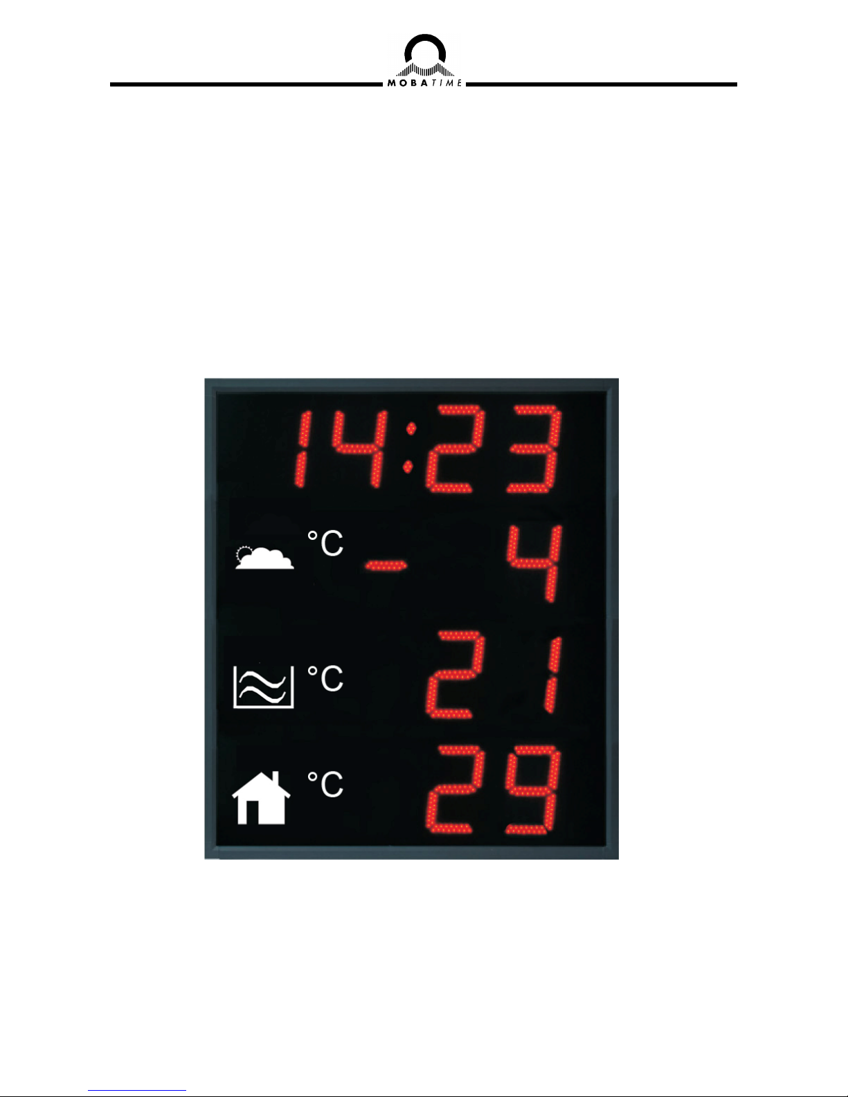
1 Description
General-purpose digital display may show up time (alternating the date) and up to three
temperatures (depending on model). It is intended for outdoor and indoor use. Display will find
use in out- and indoor swimming pools, ski resorts, industrial areas, spas, hospitals, public
buildings etc.
1.1 Basic properties
digit height of 100/57, 100 and 180 mm, which corresponds to readability
distance of 40/25, 40 and 70 m;
digits in red, pure green, blue, white or amber color;
different colors for each colon possible;
manual or automatic adjustment of the luminosity of LED displays;
antiglare front side glass with dark filter for improved readability;
single or double sided design, for wall mounting (for single-sided clock
design only), or to be suspended or fixed to wall bracket;
mounting on tiltable console, or construction with openable front glass for
easy installation procedure;
clock frame made of powder coated aluminum profiles, RAL7040 color
(light grey) as standard, any other RAL color on request;
IR remote for easy access to all functions and display configuration;
autonomous TCXO time base, with the possibility of synchronization using
the following: DCF 77 radio signal, one-minute 24 V pulses, the MOBATIME
serial code, MOBALine, RS 232, RS 485, IRIG-B or GPS;
NTP multicast or unicast synchronization in Ethernet network;
mains powered 100-240VAC; DC powering on request;
protection degree IP 65;
The display
display of time values (either 12 or 24 hours time cycle), four-digit (HH:MM)
format;
possibility of leading zero suppression when displaying the time and date;
display of temperature in °C or °F – up to three sensors connectable;
different types of temperature sensors can be combined
Accessories
DCF 77 signal receiver
GPS receiver
temperature sensors with various interface types
remote IR controller for clock set up

© MOBATIME 6 / 40 800845.01
2 Installation
The connection to the 110/230 V AC power network can only be done by authorized personnel
with appropriate qualification and training.
Connect the cables always in unpowered state – otherwise the risk of electric shock exist.
Producer is not responsible for breakdowns caused by unsuitable clock mounting on the
bearing surface.
2.1 Single-sided display with digit sizes of up to 100mm
assemble the wall mounting console if delivered disassembled;
drill appropriate number of anchoring holes in the wall for 6 mm dia wood
screws, use the mounting console as a template;
mount the console on the wall and put it into a fully tilted out position;
shift the clock body into the flipped out console arms and fix it by tightening
the screws;
dismantle the back cover of connectors on the clock body; the cover
incorporates gap with sealings for passage of cables in the inside of
the clock;
arrange all cables to appropriate length and connect them to the appropriate
terminals on the PCB; see the description of the connectors and observe the
correct polarity where necessary;
fix the cables with the holder in correct positions in order to maintain regular
spacing between the cables in the area of passing through sealing; use
apropriate force to not to damage the cables insulation;
configure the Line type jumper according to used synchronization signal
(applies only for DCF, MOBALine, Serial MOBATIME code, polarized
impulse line or IRIG-B);
mount back the connector cover;
tilt the clock into vertical position and fix the position of the console;
2.2 Single-sided display with digit sizes of 180mm
drill appropriate number of anchoring holes into the wall, of a diameter
adequate to accommodate supplied screws. As a template for marking the
position of the holes use the mounting bar.
mount the hanging bar to the wall using appropriate screws.
prepare the cables and fix them on the wall in order to be placed behind the
small rectangular cover equipped with sealed gap for the cables.
hang the display onto the bar in order to fit the two (three) hanging screws
into the pear-shaped holes.
loosen the hexagonal screws in two bottom corners and open the front
window, the gas struts help to keep the front window opened.
tighten the two (three) hanging screws using the allen key, the display is then
fixed on the hanging bar.
dismount the rectangular cover, drag the cables in and pull them inside.
arrange all cables to appropriate length and connect them to the appropriate
terminals on the PCB; see the description of the connectors and observe the
correct polarity where necessary;

© MOBATIME 7 / 40 800845.01
fix the cables with the holder in correct positions in order to maintain regular
spacing between the cables in the area of passing through sealing; use
apropriate force to not to damage the cables insulation;
configure the Line type jumper according to used synchronization signal
(applies only for DCF, MOBALine, Serial MOBATIME code, polarized
impulse line or IRIG-B);
mount back the connector cover;
close the front window and mount back the hexagonal screws into both
bottom corners – use the adequate force for fastening the screws.
click-on delivered corner covers, they can be dismounted using narrow
screwdriver.
2.3 Double-sided display
the double-side display consists of the displaying and the control part, and
the central mounting console;
assemble the mounting console if delivered disassembled;
drill appropriate number of anchoring holes in the wall for 10 mm dia wood
screws, use the mounting console as a template;
mount the console on the wall;
hang the displaying part on one side of the console, this display part does
not incorporate a cover of connectors, and is linked with the control part via
cable;
the remaining installation steps are the same as with the single-sided
display, additionally it is necessary to connect the linking cable from the
displaying part to mating connector in the control part
© MOBATIME 8 / 40 800845.01
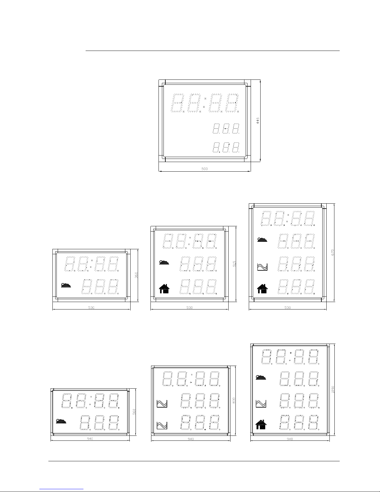
2.4 Mechanical drawings
DT.100/57.1C.2T
Luft T°
Wasser T°
°C
°C
°C
°C
DT.100.1C.1T
DT.100.1C.2T
DT.100.1C.3T
°C
°C
°C
DT.180.1C.2T
DT.180.1C.1T
DT.180.1C.3T
°C
°C
1
2
°C
°C
°C
© MOBATIME 9 / 40 800845.01
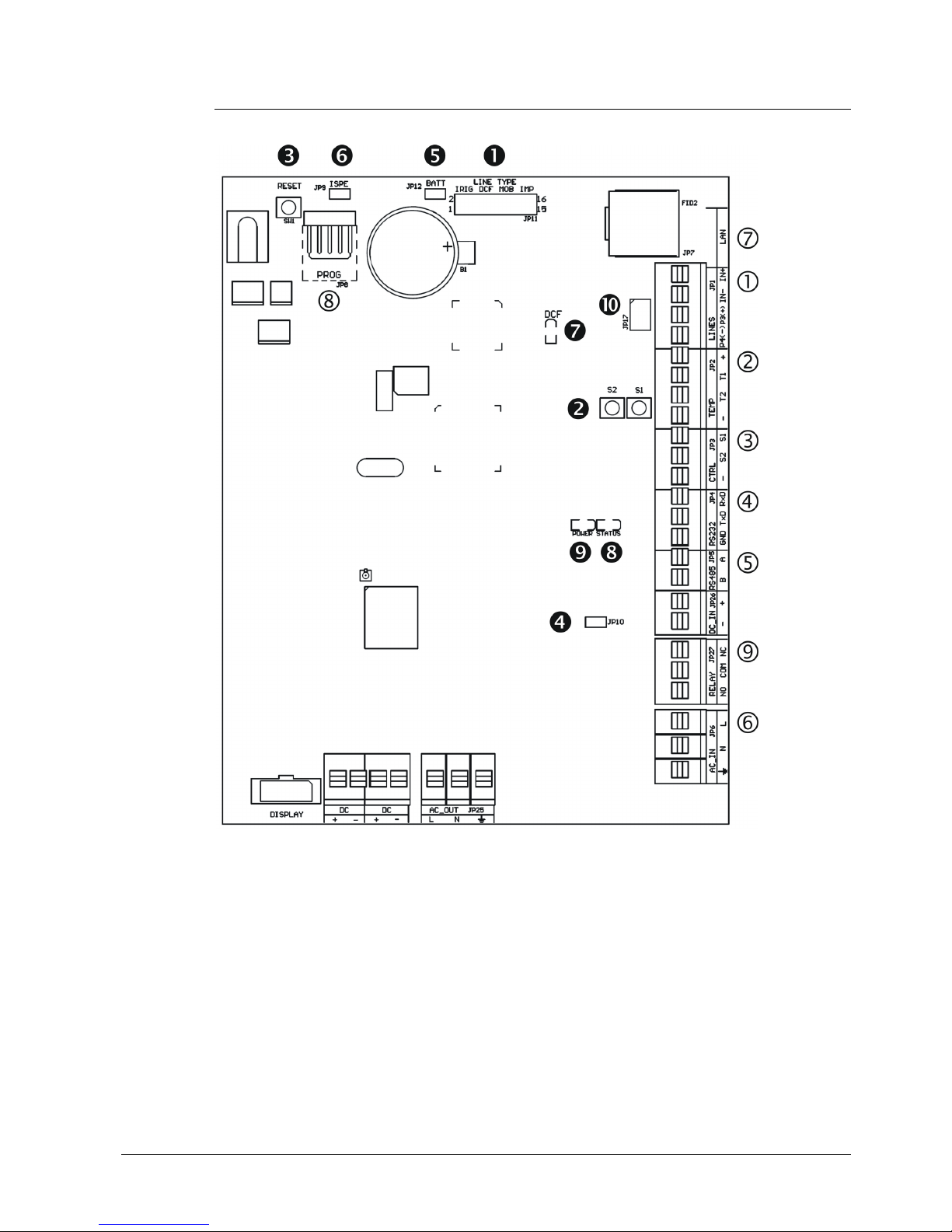
2.5 Connectors and control elements
LINES, DC/DCF OUT – JP1
TEMP – JP2
CTRL – JP3
RS232 – JP4 (version SI)
RS485 – JP5 (version SI)
100 – 240VAC – JP6
LAN - JP7 (version NTP)
PROG – JP8
RELAY – JP27 (optional)
Line type jumper – JP11
PB1, PB2 buttons
RESET button
TRE jumper – JP10 (version SI)
BATT jumper – JP12
jumper ISPE – JP9
LED indication of DCF signal
state LED
LED indication of powering
jumper DC Out / DCF Out – JP17
© MOBATIME 10 / 40 800845.01
2.6 Function of the plug connectors
LINES, DC/DCF OUT – JP1 time signal inputs: The DCF/GPS receiver,
polarized impulse line, MOBALine, MOBATIME
serial code, IRIG-B,
power supply output: DC OUT 12–40 VDC
or passive DCF current loop output
TEMP – JP2 connection of the temperature sensor(s)
CTRL – JP3 connection of the keyboard
RS232 – JP4 (optional) connection of the RS232 serial line
RS485 – JP5 (optional) connection of the RS485 serial line
100 – 240VAC – JP6 powering 100 - 240 VAC voltage
LAN - JP7 (optional) RJ45 10BaseT/100TX (IEEE 802.3)
auto negotiation
PROG – JP8 clock firmware programming
RELAY – JP27(optional) switching contact connection
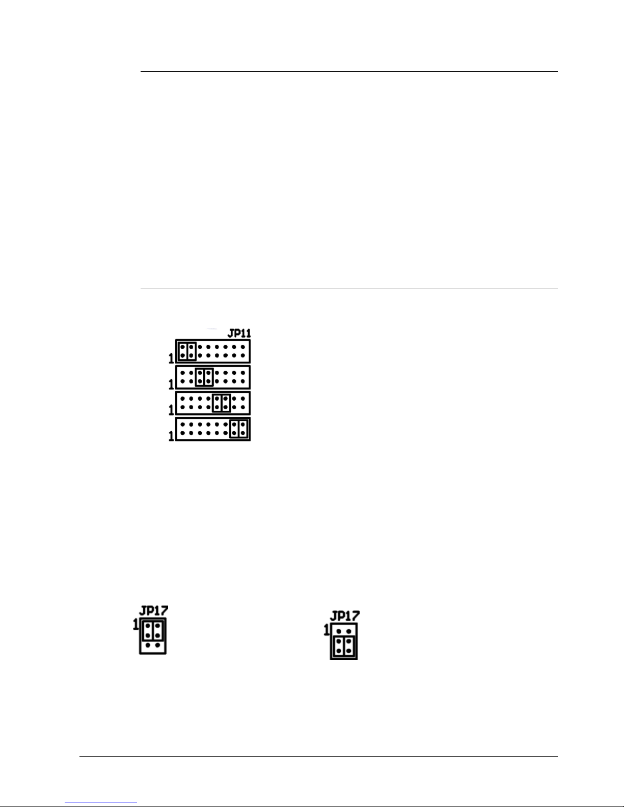
2.7 Setting elements
Line type jumper – JP11 for the setting of the slave line type
IRIG / AFNOR
DCF
MOBALine
(Un)polarized impulse line
MOBATIME serial code
PB1, PB2 control pushbuttons
RESET the RESET button
TRE jumper – JP10 (optional) RS485 terminating resistor enable
BATT jumper – JP12 backup battery connection
ISPE jumper – JP9 invoking the firmware programming mode
DCF LED indication of receiving the DCF signal
STATE LED state indication
POWER LED power indication
jumper DC Out / DCF Out – JP17 Output signal setting on pins 3, 4
of the JP1 connector
pin3 = DC Out + (12-40V)
DC Out
pin4 = DC Out -
pin3 = (+)
passive DCF Out
pin4 = (-)
© MOBATIME 11 / 40 800845.01
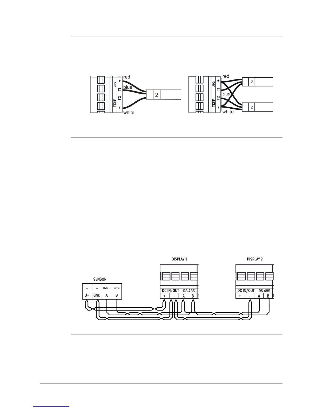
2.8 TP3, TP30 temperature sensors connection
both temperature sensor types are connected to the JP2 connector terminals
using three wires (see the illustration)
it is possible to connect up to two temperature sensors to single display
device, other displays can’t be connected to the sensor(s)
2.9 TP RS485 temperature sensors connection
the RS485 bus is used for connection of this type of temperature sensors,
there can be up to three temperature sensors connected to the bus
moreover more display units can be connected to the bus, the only limitation
is the maximum of 32 devices connected to single bus and total length of the
bus of max. 1200m
the connection is done using six-core twisted pair cable (UTP or STP)
one of the twisted pairs is used for data transmission, the others are for
temperature sensor powering (see the illustration)
using one twisted pair interconnect the pin 1 (+) of the JP24 in the display
and the + terminal on the sensor, use second twisted pair and interconnect
the pin 2 (-) of the JP24 connector in the clock and the – terminal on the
sensor
interconnect the pins A and B of the JP5 connector in the clock, and
terminals Tx+ and Tx- on the thermometer using one twisted pair. The A
signal corresponds to Tx+ and the B corresponds to Tx-.
in case you need to connect other display device, only the A, B and – signals
must be connected in parallel. The + signal must not be connected.
2.10 TP LAN temperature sensors connection
the Ethernet network is used for connection of this type of temperature
sensors, there can be any number of temperature sensors connected in the
network
moreover more display units can communicate to single temperature sensor,
single display can communicate to up to three sensors

© MOBATIME 12 / 40 800845.01
the connection is done using standard UTP or STP cable and network
infrastructure
the sensor is powered from small AC/DC wall adapter

© MOBATIME 13 / 40 800845.01
3 Setting of time synchronization type
Configure the jumper JP11 according to table (chapter 2.7.) if the source of synchronization is
DCF signal, Mobatime serial code, polarized impulse line, MOBALine or IRIG-B. Choose the
item P4 in main MENU (chapter 7) and set the type of synchronization. The auto detection
mode (P4:A), when the type of synchronization signal is set automatically, is applicable for
DCF signal, Mobatime serial code, MOBALine, IRIG-B and WTD.
The permanently lit colon during the time display signalizes the clock is synchronized by the
synchronization source.
3.1 Autonomous clock synchronized by DCF 77 receiver
Set value A in items P3, P4 and P6 in the main MENU (chapter 7).
Connect the DCF 77 receiver to the LINES connector (IN+, IN- terminals)
using a twin-wire cable.
The maximum wire length depends on its diameter (app.100 - 300 m).
In case the connection is correct and the input signal is at high level, the LED
on the receiver is flashing periodically once a second, with 1 pulse left out at
the 59th second.
In case the polarity is incorrect, the LED does not flash. In such a case,
interchange the two wires.
Install the receiver at a place with high-level radio signal. Don’t install the
receiver near sources of interfering signals, such as the personal computers,
TV sets or other types of power consumers (the digital clock itself generates
interfering signals too).
Position the receiver with its transparent cover (DCF 450) or the arrow on the
cover (DCF 4500) facing the transmitter (located in Frankfurt, Germany).
Presuming the good quality DCF 77 signal the synchronization takes place in
approx. 3 to 4 minutes. In case of poor quality of the signal (mainly during the
day time) the first time setting is to be done manually. The red LED of the
receiver displays a working connection by flashing once a second without
flickering.
3.2 Autonomous clock synchronized by GPS4500 receiver
Set value A in items P3, P4 and the desired time-zone in the P6 item in the
main MENU (chapter 7).
Using jumper JP17 set the power supply output (DC OUT) on pins 3, 4 of the
JP1 connector.
Connect GPS receiver to the LINES connector (IN+, IN- terminals for the
signal and P3+, P4- terminals for antenna powering) using a four-wire cable.
Please note the correct polarity of the wires – see the GPS user manual.
For the correct placing of the receiver please follow the GPS user manual.
Presuming the good position of the GPS receiver the synchronization takes
place in approx.10 to 20 minutes.
3.3 Autonomous clock synchronized by internal GPS receiver
Set value A in item P3, value 13 in item P4 and the desired time-zone in the
P6 item in the main MENU (chapter 7).
Connect the GPS antenna cable to dedicated SMA connector.
Place the GPS antenna according to following recommendation

© MOBATIME 14 / 40 800845.01
Presuming the good position of the GPS antenna the synchronization takes
place in approx. 6 to 8 minutes.
Reception of the GPS data is indicated by blinking GPS LED on the PCB.
3.4 Slave clock controlled by synchronizing impulses
On digital clock connected in time distribution system controlled by synchronizing
impulses choose the item P4 in the main menu and set it according type impulse
lines (one minute, half minute, second pulses). Set the value A in items P3 and
P6. Clocks are set according to the slave line time on the Master clock.
Stop the slave line on Master clock.
Set all slave clocks on the same time. Set the current date on the digital
clock. The clocks stand still and the colon flashes in 2 second interval.
Set the time of the slave line to the same time as on slave clocks.
Run the slave line on Master clock.
After receiving each impulse is displayed time increased by one minute
(or by 30 seconds or 1 second respectively)
After the expiration of run-out time the slave clocks are synchronized by the
time information generated by the master clock, the colon flashes constantly.
In case of the line fault the clock displays the right time information based on
its own quartz time base. When the normal operation of the line resumes, the
slave clock adjusts itself to the time equal to the master clock.
3.5 Slave clock controlled by MOBATIME serial code, MOBALine, or
IRIG-B
After the connection of the digital clock to the signal source, time and date
are adjusted automatically, following the receipt of valid time information.
The time setting with using the serial coded line takes place within at least 3
to 4 minutes, for MOBALine and IRIG-B within 6 to 15 seconds.
3.6 Cascaded connection of the DCF/GPS synchronised clock
Connect the DCF 77 receiver to the LINES connector (IN+, IN- terminals)
using a twin-wire cable.
Set the passive DCF OUT output 3, 4 of the JP1 connector using the jumper
JP17.
When using the GPS receiver, the external power supply is needed -
parameters 12-24 VDC – min. 5VA.

© MOBATIME 15 / 40 800845.01
Interconnect the cascaded clock using a twin-wire cable from the LINES
connector (P3+, P4- terminals) to the LINES connector (IN+, IN- terminals) of
the next clock.
In case the connection is correct and the input signal is at a high level, the
LED on the receiver and the green LED in the clock is flashing periodically
once a second, with 1 pulse left out at the 59th second.
3.7 Synchronization by NTP protocol
The NTP time synchronization can be used when the clock is connected to
Ethernet or WiFi network and the NTP server is accessible.
NTP protocol transfers data always UTC time coded, so it isn’t necessary to set
item P3 manually. Time zone of synchronization source is internally set to value 0
in this case.
3.7.1 Synchronization by NTP multicast
The clock receives NTP multicast packets transmitted by NTP server in specified
time cycle. This type of synchronization can work even when clock has not been
assigned its own IP address and so it is suitable for controlling the large system
of the slave NTP clocks. Not applicable for WiFi clock.
Set item P4 to value 9
According to chapter 6.3 set IP multicast address
For correct displaying of time and date, choose the desired time zone in the
item P6.
3.7.2 Synchronization by NTP unicast
The clock requests the exact time from the NTP server periodically in a
predefined interval. The clock must have been assigned its own IP address and
subnet mask (see chapter 5) in this case.
Set item P4 to value 10.
According to chapter 6.4 set IP address of NTP server and polling interval
For correct displaying time and date choose desired time zone in item P6.

© MOBATIME 16 / 40 800845.01
4 Setting the way of displayed time and date calculation
4.1 Basic setting – control according to source of synchronization
P3 A Time zone is taken over according to the source
of synchronization
P4 2 – 12,ASynchronization signal type
P5 0 Neither MOBALine time zone nor Timezone-
server are used
P6 A Display time and date according to source of
synchronization incl. daylight saving time
This setting is suitable for digital clocks synchronized by a DCF receiver or
controlled by a master clock as slave clock in a time distribution system. The
internal time zone table isn’t used.
4.2 Calculation using MOBALine time zones
This setting is suitable for digital clocks controlled by a master clock as a
MOBALine slave clock in a time distribution system with possibility to display
different MOBALine time zones
4.3 Calculation using Timezone-server MOBATIME
This setting is suitable for NTP digital clocks controlled by MOBATIME NTP
servers which support the Timezone-server functionality.
P3 A Time zone is taken over according to the source of
synchronization. The UTC time calculation is based
on the MOBALine information.
P4 4 MOBALine
P5 1 - 20 Selection of the MOBALine time zone
P6 A Display time and date according to chosen
MOBALine time zone, incl. daylight saving time
P3 A NTP protocol uses UTC time zone
P4 11, 12 NTP multicast or unicast
P5 1 - 15 Selection of the Timezone-server time zone
P6 A Display time and date according to chosen
Timezone-server time zone, incl. daylight saving
time

© MOBATIME 17 / 40 800845.01
4.4 Calculation according to internal time zone table
This setting is suitable for autonomous digital clocks or in cases when the
displayed time in another time zone than the one provided by the synchronization
source is needed. Displayed time and date calculation is based on the internal
time zone table or on the user–specific time zone parameters.
P3 0 – 64 According to the time zone in which source of
synchronization works (e.g. value 2 for DCF in
west Europe)
P4 1 – 13,AAutonomous operation or any type of the
synchronizing signal
P5 0 Neither MOBALine time zone nor Timezone-
server are used
P6 0 – 64,UDisplay time and date by calculation from the
UTC time according to chosen time zone, incl.
daylight saving time

© MOBATIME 18 / 40 800845.01
5 Setting the network parameters for NTP versions
In the item P17 choose if the network parameters (IP address, subnet mask, gateway NTP
servers) will be set automatically (DHCP), or manually (telnet, the clock menu), or they will not
be assigned at all (e.g. for NTP multicast).
5.1 Manually setting the network parameters using clock Menu
According to chapter 6.10 set clock’s IP address in item P18 submenu
According to chap 6.11 set subnet mask in item P19 submenu
According to chap 6.12 set gateway in item P20 submenu
5.2 Manually setting the network parameters using telnet
Prior to the first connection using telnet, it is necessary to make the following
procedure because initial IP address is 0.0.0.0.:
by windows command arp -s <IP address> <MAC address> match new IP
address to clock’s MAC address (it is marked on the label next to RJ-45
connector)
example: arp -s 192.168.0.190 00-16-91-FE-90-00
reset the clock or just turn it off/on and do the following within 2 minutes:
by windows command ping <IP address> is this IP address temporary
assigned to the clock (it is valid only in case if current IP address is 0.0.0.0),
clock should answer two last ECHO requests at least
example: ping 192.168.0.190
do the following within 30 seconds:
by windows command telnet <IP address> connect to clock and make
needed setting (see lower) – set the new IP address at first and correct other
parameters if necessary
example: telnet 192.168.0.190
Setting parameters over telnet:
request for the password appears after connection (default password is
718084)
the software and hardware version and MAC address displays if password
entering was successful
inserted commands can be send off using Enter key, the Backspace key
serves for correction of the typing errors
command help or ? displays help with command’s list
command reset makes clock reset (setting modifications are written to data
flash)
command conf -p displays current setting of the menu parameters
command conf –n displays current network parameters
command conf -? displays help for command conf parameters
example: conf -i 192.168.0.190 set clock IP address to 192.168.0.190
it is necessary to end telnet by command exit

© MOBATIME 19 / 40 800845.01
5.3 Setting of the network parameters by DHCP
The network parameters are automatically assigned by the DHCP server.
Assigned parameters can be checked in the submenu items P18 to 20. Besides
the network parameters, IP addresses up to four NTP servers can be set using
the DHCP option. Following options are supported:
Option code 42 – NTP servers
Note: For NTP address assignation, NTP unicast synchronization must be
selected.

© MOBATIME 20 / 40 800845.01
6 Control of the display using IR remote control
A 2-digit address is assigned to the clock. With the IR remote control the clock can be locked.
The setting of time, date and the clock parameters can only take place at clocks in an
unlocked state.
Function of the controller buttons in normal display mode
pushing F1 + entry of 2-digit address, unlock the clock with the
using numerical pushbuttons corresponding address
holding down F1 button unlock all clocks within the reach of the IR
beam of the remote control unit
holding down F2 button lock all clocks within the reach of the IR
beam of the remote control unit
holding down F3 button display the address of all locked clocks within
the reach of the IR beam of the remote control
CLOCK display of time on the first line (model with clock)
DATE display of date on the first line (model with clock)
MENU entry into the display configuration menu
SET entry into the time setting (model with clock)
Function of the buttons in the time setting and menu operation mode
>> move to next parameter
<< move to previous parameter
the + pushbutton increase of the value adjusted, in steps of 1
the - pushbutton decrease of the value adjusted, in steps of 1
holding the + pushbutton continuous increase of the value set up
holding the – pushbutton continuous decrease of the value set up
ESC return into normal display mode, without storage of the data
OK storage of values set up and return into normal working mode
SET entry into a submenu (where possible)
pushbuttons 0–9 entry of the corresponding numerical value
6.1 Setting of time and date
Press the SET button on the IR remote controller.
Enter the data in following order: year - day - month - hour - minutes
The display shows the year:
The actual parameter blinks, to change its value use the +, - or 0 to 9 buttons, to
move to another parameter use the << or >> buttons. To set the time press the
OK button. To exit the time setting without applying the changes press the ESC
button.

© MOBATIME 21 / 40 800845.01
6.2 Menu for the setting of the clock parameters
Press the MENU button on the IR remote controller. See the Menu table in
chapter 7.
The display shows the first parameter of the menu:
The actual parameter blinks, to change its value, use the +, - or 0 to 9 buttons, to
move to another parameter, use the << or >> buttons. To save the settings press
the OK button. To exit the menu without saving press the ESC button.
6.3 Setting of NTP multicast synchronization
Set the value 9 in the P4 (synchronization source) menu item, and then by
pushing the SET enter the submenu for setting the parameters of the NTP
multicast synchronization. The item to be set is blinking.
The display shows the following:
Enter four octets of the IP address (onto which are
send NTP multicast packets) step by step. Switch to
another octet/digit by pushing the << and >> buttons.
Octets are marked by letters A, b, C and d.
By pushing OK are the entered values stored and the display returns to the menu
item P4. By pushing ESC return to P4 item without storing.
6.4 Setting of the NTP unicast synchronization
Set the value 10 in the P4 (synchronization source) menu item, and then by
pushing SET enter the submenu for setting the parameters of the NTP unicast
synchronization. The item to be set is blinking.
The display shows the following:
Set four octets of the IP address of NTP server step
by step. Switch to another octet/digit by pushing the
<< and >> buttons. Octets are marked by letters A, b,
C and d.
After entering last octet enter constant x determining interval of synchronization
according to the following formula (in seconds): 2x.
By pushing OK are the entered values stored and the display returns to the menu
item P4. By pushing ESC return to P4 item without storing.

© MOBATIME 22 / 40 800845.01
6.5 Submenu for setting of the user-specific time zone
Choose the value U in the item P6 (time zone displaying) in clock menu, then by
pushing the SET enter the submenu for setting the parameters of the userspecific time zone.
The item to be set is blinking.
The display shows the following (example: -12 hours):
Enter the offset of the required time zone compared
to UTC time within -12 to +12 hours. Decimal dot
means 0,5 hour.
By pushing >> switch over to setting the way of setting daylight saving time
(DST).
The display shows the following:
Possibility:
n – no DST is used
F – DST defined by fixed date
C – DST defined by calculated date
Pushing the OK button returns to the clock menu item P6.
DST defined by entering fixed date and time
If the value F is set in item dt:, by pushing SET enter the submenu for entering
fixed date and time. The item to be set is blinking.
Symbols on the display:
Fh change to summer time; entry of the hour at daylight saving begins
bh shift back; entry of the hour at daylight saving ends
The display shows the following:
Enter the hour in which the daylight
saving time begins.
Push >>.
The display shows the following:
Enter the day of the month. Push >>.
Enter the month in which the daylight
saving time begins.
Push >>.
The display shows the following:
Enter the hour in which the daylight
saving time ends.
Push >>.

© MOBATIME 23 / 40 800845.01
The display shows the following:
Enter the day of the month. Push >>.
Enter the hour in which the daylight
saving time ends.
The daylight saving time has been set to start on April 28that 2 o’clock and
end on October 10that 3 o’clock in the above described example.
By pushing OK save the setting and return to item dt:, Another push of the OK
button returns to the clock menu item P6.
DST defined by entering calculated date
If the value C is set in item dt:, by pushing SET enter the submenu for the
calculated date. The item to be set is blinking.
Symbols in the display:
F change to summer time
b setting the time back
Scope of the setting:
Week 1. – 4., L (the last one), P (last but one)
and H (first after 15thday in the month)
Days of the week 1. – 7. (Mo – Su)
Month 1. – 12.
The display shows the following:
Enter the week in which the daylight
saving time begins. Push >>. Enter the
day of the week in which the daylight
saving time begins.
Push >>.
The display shows the following:
Enter the month in which the daylight
saving time begins. Push >>. Enter the
hour in which the daylight saving time
begins.
Push >>.
The display shows the following:
Enter the week in which the daylight
saving time ends. Push >>. Enter day
of the week in which the daylight saving
time ends.
Push >>.
The display shows the following:
Enter the month in which the daylight
saving time ends. Push PB1S. Enter the
hour in which the daylight saving time
ends.

© MOBATIME 24 / 40 800845.01
The daylight saving time has been set to start on last Sunday in March at 2
o’clock and end on last Sunday in October at 3 o’clock in the above
described example.
By pushing OK save the setting and return to item dt:. Another push of the OK
button returns to the clock menu item P6.
6.6 Setting of the predefined temperature value
It is possible to display a predefined temperature value in each temperature
display field without need for the temperature sensor.
Set the value 0 in the P13 (or P14 or P15 respectively) menu item, and then by
pushing the SET enter the submenu for setting the temperature preset.
The display shows Fxx.x. The item to be set is blinking.
Enter temperature preset value in format xx.x , the range is from 00.0 to 99.9
degrees.
By pushing OK, the entered values are stored and the display returns to the
menu item P13 (or P14 or P15 respectively). By pushing ESC return without
storing.
6.7 Settings for the TP3 / TP30 temperature sensors
Set the value 1 in the P13 (or P14 or P15 respectively) menu item, and then by
pushing the SET enter the submenu for setting the address and measured
temperature correction.
The display shows A : x.The item to be set is blinking.
Enter the address of the sensor, use value 1 for Temp1 input or 2 for Temp2
input. Push the >> button to move to the temperature correction setting.
The display shows cxx.x.
Enter temperature correction value in format xx.x , the range is from -9.9 to +9.9
degrees.
By pushing OK, the entered values are stored and the display returns to the
menu item P13 (or P14 or P15 respectively). By pushing ESC return without
storing.
6.8 Settings for the TP RS485 temperature sensors
Set the value 2 in the P13 (or P14 or P15 respectively) menu item, and then by
pushing the SET enter the submenu for setting the address, measured
temperature correction and communication mode.
The display shows A : x. The item to be set is blinking.
Enter the address of the sensor, see the address printed on the sensor body and
use the table in the chapter 11 for searching of the numerical representation of
the particular address.
Push the >> button to move to the temperature correction setting.
The display shows cxx.x.

© MOBATIME 25 / 40 800845.01
Enter temperature correction value in format xx.x , the range is from -9.9 to +9.9
degrees.
Push the >> button to move to the communication mode setting.
The display shows L : x.
When a 0 value is set, the display works as a master on the RS-485 bus, value 1
means the display works only as a listener on the bus. On the single RS485 bus
just one display device must be master and the others must be listeners.
By pushing OK, the entered values are stored and the display returns to the
menu item P13 (or P14 or P15 respectively). By pushing ESC return without
storing.
6.9 Settings for the TP LAN temperature sensors
Set the value 3 in the P13 (or P14 or P15 respectively) menu item, and then by
pushing the SET enter the submenu for setting the IP address, measured
temperature correction and timing value. The item to be set is blinking.
Set four octets of the IP address of NTP server step
by step. Switch to another octet/digit by pushing the
<< and >> buttons. Octets are marked by letters A, b,
C and d.
After entering the last octet push the >> button to move to the temperature
correction setting.
The display shows cxx.x.
Enter temperature correction value in format xx.x , the range is from -9.9 to +9.9
degrees.
Push the >> button to move to the timing value setting.
The display shows n :xx.
Set the value xx according to predicted number of display units, which should
communicate with the actual temperature sensor. Then the apropriate timing for
the communication with the sensor is applied.
By pushing OK, the entered values are stored and the display returns to the
menu
6.10 Manual setting of the IP address of the clock
Choose the item P18 in the main menu and push the SET button to enter the
submenu for setting the IP address. The item to be set is blinking.
The display shows the following:
Enter four octets of the IP address step
by step. Switch to another octet by
pushing the << and >> buttons. Octets
are marked by letters A, b, C and d.
By pushing OK, the entered values are stored and the clock returns to the menu
item P18. By pushing ESC the clock returns to P18 without storing.
6.11 Manual setting of the subnet mask
Choose the item P19 in the main menu and push the SET button to enter the
submenu for setting the subnet mask. The item to be set is blinking.

© MOBATIME 26 / 40 800845.01
The display shows the following:
Enter the four octets of the subnet mask
step by step. Switch to another octet by
pushing the << and >> buttons. Octets
are marked by letters A, b, C a d.
By pushing OK, the entered values are stored and the clock returns to the menu
item P19. By pushing ESC, the clock returns to P19 without saving.
6.12 Manual setting of default gateway IP address
Choose the item P20 in the main menu and push the SET button to enter the
submenu for setting the default gateway IP address, the item to be set is blinking.
The display shows the following:
Enter the four octets of the gateway IP
address step by step. Switch to another
octet by pushing the << and >> buttons.
Octets are marked by letters A, b, C
and d.
By pushing OK, the entered values are stored and the clock returns to the menu
item P20. By pushing ESC, the clock returns to P20 without saving.

© MOBATIME 27 / 40 800845.01
7 MENU table
Program
item
Function
Scope of the values
(default values are printed in bold)
P0 Display brightness
1-30
, A
(automatic adjustment, without the possibility
of changing in normal display mode)
P1 Time display format
24 h
, 12 h
P2 Time constants for
automatic data
switching over
0 automatic switching over disabled
1
continuous display of time
2 continuous display of date
3 display sequence: time 6 sec, date 3 sec.
P3 Time zone
of synchronization
source
0 - 64,A(automatically)
P4 Synchronization
source
1 - 10,A(automatically)
A
auto detection, applicable for: DCF,
the Mobatime serial code, MOBALine,
WDT or IRIG-B
1 autonomous operation without synchronization
2 synchronization by DCF signal
3 the MOBATIME serial code
4 MOBALine
5 24 V DC impulses, at minute intervals
6 24 V DC impulses at half minute intervals
7 24 V DC impulses at second intervals
8 DCF-FSK, IRIG-B Standard, IRIG-B 123,
IRIG-B DIEM, AFNOR A, AFNOR C
9* NTP multicast
10* NTP unicast
P5 Time zone
for MOBALine or
Timezone-server
MOBATIME
1-20,0(off) – for MOBALine synchronization
or
1-15, 0 (off) – for NTP synchronization
P6 Time zone
of displayed time
and date
0 - 64,A(automatically), U* (user time zone)
P7 Time format display
1
-2
1 time with leading zero
2 time without leading zero
P8 Date format display
1-
2
1 date with leading zero
2 date without leading zero
P9 Clock address for IR
remote control
1-
99
P10 Time in minutes for
"automatic lock" since
the last depression of
button on the IR unit
1-60,U("automatic lock" is OFF)
P11 Temperature units
display
°C
°F
P12 Temperature format
display
0
with decimal part
1 without decimal part

© MOBATIME 28 / 40 800845.01
P13
Temperature 1 function
0
use preset value
1 TP3/TP30
2 TP RS485
3 TP LAN
P14
Temperature 2 function
0
use preset value
1 TP3/TP30
2 TP RS485
3 TP LAN
P15
Temperature 3 function
0
use preset value
1 TP3/TP30
2 TP RS485
3 TP LAN
P 16 Clock mode operation
0
Normal mode
1 Special mode 1
2 Special mode 2
P17 Mode of setting the
network parameters
1
without IP address (NTP multicast only)
2 Manually
3 DHCP
P18 IP address IP* Manual setting
P19 Subnet mask Su* Manual setting
P20 Gateway Gt* Manual setting
SW version r_._(e.g.: r1.10)
Note: in values marked with * the submenu is accessible by pushing the
SET
buttton

© MOBATIME 29 / 40 800845.01
8 Testing mode, parameter reset
8.1 Synchronization test
The synchronization signal receive process can be displayed in special testing
mode. This can be useful for example when the problems with the DCF signal
receipt appear.
Display description during synchronization test mode:
Two digits on the left side show the current DCF bit number (goes up from 0 to
58). Third digit show the type of current DCF bit (0 or 1). The last digit shows the
number of successfully received DCF telegrams. The colon indicates that the
DCF bit is currently received. The dot behind the last digit signalizes
synchronized clock.
Entering the synchronization test mode:
Enter the clock menu and keep pushing simultaneously both buttons on the
clock PCB or the DISP button on the IR controller, until the display shows
C0:00
Use the PB2 or + button on IR to set the value behind the colon to 03
Keep pushing simultaneously both clock PCB buttons or the DISP button on
IR, until the display shows synchronization information
8.2 Parameter reset
If necessary, the clock parameters can be set to factory defaults by the following
procedure.
Activating the parameter reset:
Enter the clock menu and keep pushing simultaneously both buttons on the
clock PCB or the DISP button on the IR controller, until the display shows
C0:00
Using the PB2 or + button on IR set the value behind the colon to 04
Keep pushing simultaneously both clock PCB buttons or the DISP button on
IR, until the display shows FAC1 and clock makes reset

© MOBATIME 30 / 40 800845.01
9 Update firmware
9.1 Update firmware using RS232
Switch-off the clock.
Install and run the Flash Magic software.
Open the configuration file „dc3prog.fms“ over the File -> Open Settings
menu
Set used COM Port and open file firmware „dc3.hex“using the Browse key
Connect the programmer to serial COM Port of computer (the USB-RS232
converter can be used) and connect the power supply to the jack on the
programmer.
Install the jumper ISPE (JP9).
Connect the programmer to connector PROG (JP8), LED POWER placed on
the clock lights up.
Click the Start button to run programming, after completion a “Finished”
message will be displayed in the bottom part of the widow
Disconnect the programmer and remove the ISPE jumper.
Firmware version can be checked in the last item of clock menu.
9.2 Update firmware over Ethernet at NTP version
Create a folder on the computer disk and copy "tftpd32.ini", "tftpd32.chm" and
"tftpd32.exe" in it. Copy the file of new firmware "dc3app.bin" as well.
Run "tftpd32.exe" let only TFTP Server in the window Settings -> Global
Settings set, don’t change other settings.
By the Browse key open choice of active directory and find the one which
contains the given firmware
Connect to the clock by the windows command telnet <ip clock address>
example: telnet 192.168.0.190
The page of telnet requesting will appear, after the password entered
identification of current software version and clock MAC address displays.
Enter the command fu in telnet window for start the automatic update clock
firmware from the "dc3app.bin" file.
Information about sending file and its progress displays in the tftpd32
programme window after the command entering. Connection to telnet is
ended automatically.
Wait about 1 minute after end of sending. Connect the telnet to clock again.
After entering the password, check if the firmware version is correct, if it isn’t,
it is necessary to repeat the whole procedure.
Close the telnet window and end the program tftpd32 with the command exit.

© MOBATIME 31 / 40 800845.01
10 Time zone table
Time zone entries in the standard time zone table (version 10.0).
Time
zone
City / State UTC
Offset
DST
Change
Standard → DST DST → Standard
00 UTC (GMT),
Monrovia, Casablanca
0 No
01 London, Dublin,
Edinburgh, Lisbon
0 Yes Last Sun. Mar. (01:00) Last Sun. Oct. (02:00)
02 Brussels, Amsterdam,
Berlin, Bern,
Copenhagen, Madrid,
Oslo, Paris, Rome,
Stockholm, Vienna,
Belgrade, Bratislava,
Budapest, Ljubljana,
Prague, Sarajevo,
Warsaw, Zagreb
+1 Yes Last Sun. Mar. (02:00) Last Sun. Oct. (03:00)
03 Athens, Istanbul, Helsinki,
Riga, Tallinn, Sofia,
Vilnius
+2 Yes Last Sun. Mar. (03:00) Last Sun. Oct. (04:00)
04 Bucharest, Romania +2 Yes Last Sun. Mar. (03:00) Last Sun. Oct. (04:00)
05 Cairo, Pretoria, Harare +2 No
06 Amman +2 Yes Last Thu. Mar. (23:59) Last Fri. Oct. (01:00)
07 UTC (GMT) 0 No
08 Kuwait City, Minsk,
Kaliningrad
+3 No
09 Praia, Cape Verde -1 No
10 UTC (GMT) 0 No
11 Abu Dhabi, Muscat,
Tbilisi, Moscow, St.
Petersburg, Volgograd,
Samara
+4 No
12 Kabul +4.5 No
13 Adamstown (Pitcairn Is.) -8 No
14 Tashkent, Islamabad,
Karachi
+5 No
15 Mumbai, Calcutta,
Madras,
New Delhi, Colombo
+5.5 No
16 Astana, Thimphu, Dhaka,
Yekaterinburg
+6 No
17 Bangkok, Hanoi, Jakarta,
Novosibirsk
+7 No
18 Beijing, Chongqing, Hong
Kong, Singapore, Taipei,
Urumqi, Krasnoyarsk
+8 No
19 Tokyo, Osaka, Sapporo,
Seoul, Irkutsk
+9 No
20 Gambier Island -9 No
21 South Australia: Adelaide +9.5 Yes 1stSun. Oct (02:00) 1stSun. Apr. (03:00)
22 Northern Territory: Darwin +9.5 No
23 Brisbane, Guam, Port
Moresby, Yakutsk
+10 No
24 Sydney, Canberra,
Melbourne, Tasmania:
Hobart
+10 Yes 1stSun. Oct. (02.00) 1stSun. Apr. (03:00)
25 UTC (GMT) 0 No
26 UTC (GMT) 0 No

© MOBATIME 32 / 40 800845.01
27 Honiara (Solomon Is.),
Noumea (New
Caledonia), Vladivostok
+11 No
28 Auckland, Wellington +12 Yes Last Sun. Sep. (02:00) 1stSun. Apr. (03:00)
29 Majuro (Marshall Is.),
Magadan, Anadyr
+12 No
30 Azores -1 Yes Last Sun. Mar. (00:00) Last Sun. Oct. (01:00)
31 Middle Atlantic -2 No
32 Brasilia -3 Yes 3rdSun. Oct. (00:00) 3rdSun. Feb. (00:00)
33 Buenos Aires -3 No
34 Newfoundland, Labrador -3.5 Yes 2ndSun. Mar. (02:00) 1stSun. Nov. (02:00)
35 Atlantic Time (Canada) -4 Yes 2ndSun. Mar. (02:00) 1stSun. Nov. (02:00)
36 La Paz -4 No
37 Bogota, Lima, Quito -5 No
38 New York, Eastern Time
(US & Canada)
-5 Yes 2ndSun. Mar. (02:00) 1stSun. Nov. (02:00)
39 Chicago, Central Time
(US & Canada)
-6 Yes 2ndSun. Mar. (02:00) 1stSun. Nov. (02:00)
40 Tegucigalpa, Honduras -6 No
41 Phoenix, Arizona -7 No
42 Denver, Mountain Time -7 Yes 2ndSun. Mar. (02:00) 1stSun. Nov. (02:00)
43 Los Angeles, Pacific Time -8 Yes 2ndSun. Mar. (02:00) 1stSun. Nov. (02:00)
44 Anchorage, Alaska (US) -9 Yes 2ndSun. Mar. (02:00) 1stSun. Nov. (02:00)
45 Honolulu, Hawaii (US) -10 No
46 Midway Islands (US) -11 No
47 Mexico City, Mexico -6 Yes 1stSun. Apr. (02:00) Last Sun. Oct. (02:00)
48 Adak (Aleutian Is.) -10 Yes 2ndSun. Mar. (02:00) 1stSun. Nov. (02:00)
49 UTC (GMT) 0 No
50 UTC (GMT) 0 No
51 UTC (GMT) 0 No
52 UTC (GMT) 0 No
53 UTC (GMT) 0 No
54 Scoresbysund, Greenland -1 Yes Last Sun. Mar. (00:00) Last Sun. Oct. (01:00)
55 Nuuk, Greenland -3 Yes Last Sat. Mar. (22:00) Last Sat. Oct. (23:00)
56 Qaanaaq, Greenland -4 Yes 2ndSun. Mar. (02:00) 1stSun. Nov. (02:00)
57 Western Australia: Perth +8 No
58 Caracas -4.5 No
59 CET standard time +1 No
60 Santiago, Chile -4 Yes 2ndSun. Oct. (00:00) 2ndSun. Mar. (00:00)
61 Chile, Easter Island -6 Yes 2ndSat. Oct. (22:00) 2ndSat. Mar. (22:00)
62 Baku +4 Yes Last Sun. Mar. (04:00) Last Sun. Oct. (05:00)
63 UTC (GMT) 0 No
64 UTC (GMT) 0 No
In countries where the DST switch date changes annually (e.g. Iran, Israel), the time zone has to be
defined manually in the user time zone table (entries 80 – 99).
Legend:
UTC: Universal Time Coordinate, equivalent to GMT
DST: Daylight Saving Time
DST Change: Daylight Saving Time changeover
Standard DST: Time change from Standard time (Winter time) to Summer time
DST Standard: Time change from Summer time to Standard time (Winter time)
Example:
2ndlast Sun. Mar. (02:00) Switch over on the penultimate Sunday in March at 02.00 hours local time
Attention! The Time Zone Table is usually updated every year. The current table is available for download under the
following address: www.mobatime.com Customer Area Customer Support Support Resources
Software Tools Time Zone Table. In case your device is equipped with a newer version than shown in this
manual, the current time zone settings should be checked.

© MOBATIME 33 / 40 800845.01
11 Table of the addresses for the TP RS485 sensor
Addr.
Num.
Addr.
Num.
Addr.
Num.
Addr.
Num.
Addr.
Num.
Addr.
Num.
0 0 c 12 o 24 A 36 M 48 Y 60
1 1 d 13 p 25 B 37 N 49 Z 61
2 2 e 14 q 26 C 38 O 50
3 3 f 15 r 27 D 39 P 51
4 4 g 16 s 28 E 40 Q 52
5 5 h 17 t 29 F 41 R 53
6 6 i 18 u 30 G 42 S 54
7 7 j 19 v 31 H 43 T 55
8 8 k 20 w 32 I 44 U 56
9 9 l 21 x 33 J 45 V 57
a 10 m 22 y 34 K 46 W 58
b 11 n 23 z 35 L 47 X 59
Example:
Sensor address ‘M’ -> number 48

© MOBATIME 34 / 40 800845.01
12 Engineering data
12.1 Standard design of the display
Technical data
DT.100.1C.1T
DT.180.1C.1T
DT.100.1C.2T
DT.180.1C.2T
DT.100.1C.3T
DT.180.1C.3T
DT.100.2C.1T
DT.180.2C.1T
DT.100.2C.2T
DT.180.2C.2T
DT.100/57.1C.2
Digit height
100 mm or 180 mm according to version 100 / 57 mm
Display colours red / yellow / pure green / blue / white
Number of rows 2 3 4 3 4 3
Time / Date / Display 1
Time / Date / Display 2
Temperature display 1
Temperature display 2
Temperature display 3
Power supply
AC standard 100- 240 VAC, 50 - 60 Hz
DC on request 24 VDC ± 20%
Power
consumption
DT.100 20 - 30 VA 30 - 45 VA 45 - 60 VA 30 - 45 VA 45 - 60 VA 28 VA
DT.180 30 - 36 VA 45 - 69 VA 60 - 92 VA 45 - 69 VA 60 - 92 VA
Timekeeping in ambient temperature
-25 - +60 °C
± 0,3 s / day (accuracy without synchronization)
Temperature
measurement
accuracy
-55 ÷-10 °C ± 2°C
- 10 ÷ + 85 °C ±0,5°C
+ 85 ÷ + 99,5 °C ± 2°C
Operating temperature - 25 to + 60 °C, (0 to 95% humidity non condensing)
Range of measured temperature - 55 to + 99,9 °C,
Protection degree IP 65
Weight [kg] (approx.)
DT.100 9,5 13,5 17 13,5 17 8,5
TD.180 24 35 44 35 44
Dimension
[mm](approx.)
DT.100 530x360x60 530x515x60 530x670x60 560x515x60 530x670x60 500x446x60
DT.180 940x560x60 940x830x60 940x1090x60 940x830x60 940x1090x60
12.2 Voltage range and electric current consumption of the lines
Type of slave line
Voltage range
Electric current consumption
MOBALine 5 – 30 VAC 6 – 34 uA
MIN, CODE +- 12 – 30 V 10 – 18 mA
MIN, CODE (on request) +- 30 – 60 V 10 – 18 mA
IRIG B 20 mVpp – 2 Vpp 20 uA – 2 mA

© MOBATIME 35 / 40 800845.01
13 Accessories
13.1 Single sided display
Instruction manual 1 pc
IR remote control unit 1 pc
Wood screws for fixing the console 4 (6) pcs
including dowels
13.2 Double side display
Instruction manual 1 pc
IR remote control unit 1 pc
Wood screws for fixing the suspension 4 (8) pcs
including dowels
13.3 Optional accessories
AD 450 radio signal receiver
AD 10 radio signal receiver (high selectivity )
GPS 4500 receiver
magnetic GPS antenna for internal GPS receiver with cable 5m
TP 3m - temperature sensor, IP 66, with cable 3 m
TP 30m - temperature sensor, IP 66, with cable 30 m
TP RS485 - temperature sensor with RS 485 interface, power supply
12 VDC, without cable (max. length 1200m)
TP LAN - temperature sensor with Ethernet interface, power supply 5 VDC,
cable between sensor and interface 3 m
14 Cleaning
Clean surface of clock only. Use soft rags and antistatic detergents. Don’t use synthetics.
15 Disposal of used batteries
The user is lawfully obligated to return unusable batteries. Disposal of used
batteries through household waste is prohibited! Batteries which contain
dangerous substances are labeled with a picture of a crossed out trash bin.
The symbol means that this product may not be disposed through
household waste. Below the symbol, the dangerous substance is indicated
with an abbreviation: Cd = Cadmium, Hg = Quicksilver, Pb = Lead.
Unusable batteries can be returned free of charge at appropriate collection
points of your waste disposal company or at shops that sell batteries. By
doing so, you fulfill your legal responsibilities and help protect the
environment.

© MOBATIME 36 / 40 800845.01
16 Guarantee and maintenance
The device is intended for a normal operational environment according to the
corresponding norm.
The following circumstances are excluded from the guarantee:
- inappropriate handling or interventions
- chemical influences
- mechanical defects
- external environmental influences (natural catastrophes)
Repairs during and after the guarantee period are assured by the manufacturer.

© MOBATIME 37 / 40 800845.01

© MOBATIME 38 / 40 800845.01

© MOBATIME 39 / 40 800845.01

© MOBATIME BE-800845.01
PRODUCTION / HEADQUARTER
MOSER-BAER AG
Spitalstrasse 7 CH-3454 Sumiswald
Tel. +41 34 432 46 46 Fax. +41 34 432 46 99
moserbaer@mobatime.com www.mobatime.com
SALES WORLDWIDE
MOSER-BAER SA – EXPORT DIVISION
19 chemin du Champ-des-Filles CH-1228 Plan-les-Ouates/GE
Tel. +41 22 884 96 11 Fax. +41 22 884 96 90
export@mobatime.com www.mobatime.com
SALES SWITZERLAND
MOBATIME AG
Stettbachstrasse 5 CH-8600 Dübendorf
Tel. +41 44 802 75 75 Fax +41 44 802 75 65
info-d@mobatime.ch www.mobatime.ch
MOBATIME SA
En Budron H 20 CH-1052 Le Mont-sur-Lausanne
Tél. +41 21 654 33 50 Fax +41 21 654 33 69
info-f@mobatime.ch www.mobatime.ch
 Loading...