

Page 1
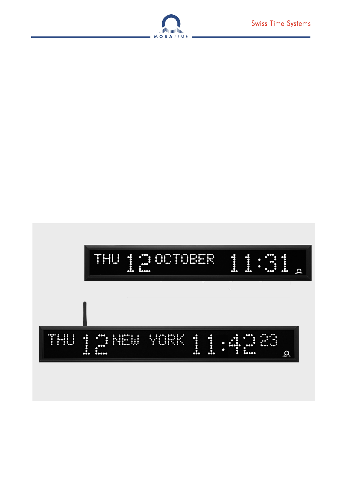
MOUNTING AND
INSTRUCTION MANUAL
DK series
State-of-the-art technology digital calendar clock
© MOBATIME BE-800444.05
Page 2

Certification of the Producer
STANDARDS
The digital calendar clock DK has been developed and produced in accordance with the EU Standards
2004 / 108 / EG and 2006 / 95 / EG:
Applied Standards:
mod IEC 60950-1:2005 + IEC-1:2005/Cor.1:2006-08
EN 55022:1998,+A1:2000,+A2:2003,+Cor.2:2003, class B
EN 61000-3-2:2000
EN 61000-3-3:1995, Cor. 1:1997, A1:2001
EN 61000-6-2:2001
EN 50121-4:2000
References to the Instruction Manual
1. The information in this Instruction Manual can be changed at any time without notice.
The current version is available for download on www.mobatime.com.
2. This Instruction Manual has been composed with the utmost care, in order to explain all details in
respect of the operation of the product. Should you, nevertheless, have questions or discover errors
on this manual, please contact us.
3. We do not answer for direct or indirect damages, which could occur, when using this Manual.
4. Please read the instructions carefully and only start setting-up the product, after you have correctly
understood all the information for the installation and operation.
5. The installation must only be carried out by skilled staff.
6. It is prohibited to reproduce, to store in a computer system or to transfer this publication in a way
or another, even part of it. The copyright remains with all the rights with BÜRK MOBATIME GmbH,
D-78026 VS-Schwenningen and MOSER-BAER AG – CH 3454 Sumiswald / SWITZERLAND.
© MOBATIME 2 / 56 800444.05
Page 3

Table of contents
1 Description .....................................................................................................................................................5
2 Assembly........................................................................................................................................................7
2.1 Single-sided clock ....................................................................................................................................7
2.2 Double-sided clock...................................................................................................................................7
2.3 Dismantling of the clock rear cover..........................................................................................................9
2.4 Assembly diagram....................................................................................................................................9
2.5 Connecting terminal block......................................................................................................................10
2.6 Control PCB ...........................................................................................................................................11
2.7 Function of the plug connectors.............................................................................................................12
2.8 Setting elements.....................................................................................................................................12
2.9 Connection of the cable ends.................................................................................................................13
3 Control of the clock using keyboard or pushbuttons..............................................................................14
3.1 Setting of time and date .........................................................................................................................14
3.2 Menu for the setting of the clock parameters.........................................................................................15
3.2.1 Submenu for user-specific setting of time constants for data switchover ......................................15
3.2.2 Submenu for setting of the user-specific time zone .......................................................................15
3.2.3 Submenu for network services configuration .................................................................................17
3.2.4 Manual setting of the IP address of the clock.................................................................................18
3.2.5 Manual setting of the subnet mask.................................................................................................18
3.2.6 Manual setting of default gateway IP address ...............................................................................18
3.2.7 Submenu for setting the multicast group address..........................................................................19
3.2.8 Submenu for the setting of the NTP unicast synchronization ........................................................19
3.2.9 Temperature description and time-zone names definition (MENU page no. 2).............................19
4 Control of the clock using IR remote control............................................................................................21
4.1 Setting of time and date .........................................................................................................................21
4.2 Menu for the setting of the clock parameters.........................................................................................22
4.2.1 Submenu for user-specific setting of time constants for data switchover ......................................22
4.2.2 Submenu for setting of the user-specific time zone .......................................................................23
4.2.3 Submenu for network services configuration .................................................................................25
4.2.4 Manual setting of the IP address of the clock.................................................................................25
4.2.5 Manual setting of the subnet mask.................................................................................................26
4.2.6 Manual setting of default gateway IP address ...............................................................................26
4.2.7 Submenu for setting the multicast group address..........................................................................26
4.2.8 Submenu for the setting of the NTP unicast synchronization ........................................................26
4.2.9 Temperature description and time-zone names definition (MENU page no. 2).............................27
5 The clock menu table ..................................................................................................................................28
5.1 Menu page no. 1 – basic clock parameters ...........................................................................................28
5.2 Menu page no. 2 – display parameters..................................................................................................30
6 Control of the stopwatch via keyboard .....................................................................................................32
6.1 The stopwatch menu..............................................................................................................................32
6.2 Setting of the initial time for counting down ...........................................................................................32
7 Control of the stopwatch using IR remote control...................................................................................33
7.1 The stopwatch menu..............................................................................................................................33
7.2 Setting of initial time for counting down..................................................................................................34
7.3 Switching contact ...................................................................................................................................34
8 Stopwatch menu table.................................................................................................................................35
9 Local time calculation .................................................................................................................................37
© MOBATIME 3 / 56 800444.05
Page 4

9.1 Basic setting – control according to source of synchronization .............................................................37
9.2 Calculation using MOBALine time zones and time zone display...........................................................37
9.3 Calculation using time zone server MOBATIME and time zone display................................................37
9.4 Calculation using time zone entries preconfigured by MOBA-NMS software and time zone display....38
9.5 Calculation according to internal time zone table and time zone display ..............................................38
10 Non-network clock operation .....................................................................................................................39
10.1 Autonomous clock synchronized by DCF 77 receiver ...........................................................................39
10.2 Autonomous clock synchronized by GPS receiver................................................................................39
10.3 Slave clock controlled by synchronizing impulses .................................................................................39
10.3.1 Synchronization and time setting – P5 mode 1 and 3....................................................................40
10.3.2 Synchronization only – P5 mode 2 and 4.......................................................................................40
10.4 Slave clock controlled by MOBATIME serial code, MOBALine, or IRIG-B............................................40
10.5 Slave clock controlled by IF482 over RS232 or RS485.........................................................................40
10.6 Slave clock controlled by supervised RS485.........................................................................................41
10.7 Cascaded connection of the DCF/GPS synchronized clock..................................................................41
10.8 Synchronization in WTD system............................................................................................................41
10.9 Connecting the slave displays through RS485 ......................................................................................41
11 NTP and PoE clock operation.....................................................................................................................42
11.1 Unicast mode .........................................................................................................................................42
11.1.1 Network parameters assignation by DHCP....................................................................................42
11.1.2 Manual setting through setup menu...............................................................................................43
11.1.3 Manual setting through telnet .........................................................................................................43
11.1.4 SNMP .............................................................................................................................................44
11.2 Multicast mode.......................................................................................................................................44
12 WiFi clock operation....................................................................................................................................45
12.1 Parameters of default wireless network.................................................................................................45
12.2 Setting process.......................................................................................................................................45
13 Testing mode, parameter reset...................................................................................................................47
13.1 Synchronization test...............................................................................................................................47
13.2 Parameter reset......................................................................................................................................47
14 Firmware update ..........................................................................................................................................48
14.1 Firmware update using RS232...............................................................................................................48
14.2 Firmware update over Ethernet on NTP and PoE versions...................................................................48
15 Time zone table ............................................................................................................................................49
16 Character set ................................................................................................................................................51
17 Additional information.................................................................................................................................54
17.1 Accessories - single-sided clock ............................................................................................................54
17.2 Accessories - double side clock.............................................................................................................54
17.3 Cleaning.................................................................................................................................................54
17.4 Disposal of used batteries......................................................................................................................54
17.5 Guarantee and maintenance..................................................................................................................54
18 Technical data ..............................................................................................................................................55
18.1 Standard design of the clock..................................................................................................................55
18.2 Voltage range and electric current consumption of the lines.................................................................55
© MOBATIME 4 / 56 800444.05
Page 5

1 Description
Clock simultaneously displays time and date information • one single display unit can be
selected to alternate between 3 different languages • support for more than 20 languages for
date information • autonomous operation with internal quartz powered from mains • NTP
multicast or unicast synchronization in Ethernet or WiFi network powered over PoE or mains
powered • slave clock operation in wireless WTD system based on a transmitter which sends
the time signal • slave clock operation controlled by self-setting MOBALine code mains
powered • slave clock operation controlled by built-in RS 232, RS 485 or IRIG-B interface,
mains powered • LED display in red, green, yellow and blue • single or double-sided clock •
clock frame made of anodized aluminum profiles • wall mounting for single-sided clock • ceiling
suspension or wall bracket mounting for double as well as single-sided clock • IP 40
Basic properties
digit height of 57 mm, which corresponds to readability distance of approx. 25 meters,
character height 30 mm (36 mm including diacritics)
color of the digits: red or green, yellow and blue on request
manual or automatic setting of the LED display light intensity
anti-reflex front cover acrylic glass which prevents light reflection and improves the digit
readability
single-sided or double-sided design, for wall mounting (for single-sided clock design,
only), or to be suspended on ceiling or fixed to a side kick up console
depth of single-sided clock design only 39 mm or 78 mm for the double-sided design)
clock frame made of anodized aluminum profiles, in black or silver color. Any other RAL
tint or imitation of various materials (wood, marble…) on request
clock setting carried out remotely or using two push-buttons, the latter installed at the
upper part of the frame
autonomous, quartz controlled time base with the possibility of synchronization using the
following: DCF 77 radio signal, 24 V minute impulses, the MOBATIME serial code,
MOBALine, RS 232, RS 485, IRIG-B or GPS
NTP multicast or unicast synchronization in Ethernet or unicast synchronization in WiFi
network powered over PoE or mains powered
configuration / supervision by means of MOBA-NMS software or SNMP protocol
slave clock operation in wireless WTD system (868 MHz) based on a transmitter which
broadcasts the time signal
possibility to set up the world time zones with indication of the time shift (DST) for the
particular time zone. Control over the DCF receiver or the master clock
The clocks
time display in 12 or 24 hour cycle; four-digit (HH:MM) or six-digit (HH:MM:SS) format.
display of weekday – 3 characters
characters display of month name – 8 characters
possibility of leading zero suppression when displaying the time and date.
temperature indication (providing the temperature sensor is connected) in °C or °F.
alternating indication of time, date and temperature, with adjustable period of each of the
displayed data.
© MOBATIME 5 / 56 800444.05
Page 6

Stopwatch
counting up, starting from zero, up to 99 hours;
countdown from a set up value, with stop at zero, automatic restart or counting to
negative values;
indication of intermediate times, “freezing“ of the display, cumulated interim time;
counting in steps of one minute, one second or 1/100 second;
control using the keyboard or IR remote control;
concurrently, possibility of changeover into the time/date display mode, or the temperature
indication.
Accessories
DCF 77 signal receiver
temperature sensor with protection degree IP 66
keyboard for stopwatch control, connected via 5 m cable
remote IR controller for clock set up and stopwatch control
On request
internal relay – relay can switch for specified duration, when the stopwatch in the
countdown mode reach the zero.
protection degree IP 54
© MOBATIME 6 / 56 800444.05
Page 7
2 Assembly
The connection to the 110/230 V AC power network can only be done by authorized personnel
with appropriate qualification and training.
Danger of electric shock when dismounting the cover with warning triangle.
2.1 Single-sided clock
The frame is fixed using two suspensions (at the above) and two sliding springs (at
the bottom). Lift-off the anchoring plate using a screwdriver inserted in between the
sheet and the frame at the sliding spring point on the clock bottom side (chapter
2.3).
Disconnect the interconnecting cables by decoupling the terminals on the control
PCB.
Drill three anchoring holes into the wall, of a diameter adequate to accommodate
wood-type screws of 4 to 5 mm diameter. As a template for marking the position of
the holes the anchoring plate can be used.
Interlace the incoming conductors through the opening in the anchoring plate and fix
the sheet to the wall.
Connect the incoming conductors in accordance with the descriptive sheet on the
terminal board, placed on the anchoring plate (chapter 2.5). Give the conductors an
appropriate shape or cut them off to a length that will not obstruct the placement of
the clock onto the anchoring plate.
Mount the connectors to the cable of the temperature sensor, to the keyboard cable,
Ethernet or to the RS 232 and RS 485 interface cables, if these have been
delivered.
Push the temperature sensor connector, the keyboard connector, Ethernet
connector or the RS 232 and RS 485 jacks into the corresponding terminals on the
control PCB (chapter 2.6 and 2.9). Check the marking of the jack-plugs, in order to
prevent their mix-up.
Connect the interconnecting cables into the corresponding terminals on the clock
control PCB.
Put the clock opposite to the anchoring plate and suspend it onto the upper springs.
Care should be taken when placing the cables between the frame edge and the
anchoring plate, so as not to nip them. Snap the clock in onto the springs by pushing
on the lower part of the frame.
Check whether the anchoring plate on the sides fits exactly into the groove in the
clock frame.
Remove the blind cap from the opening on the clock bottom side.
Insert Allen key into the opening on the bottom side of the clock. Turn the key softly
in anticlockwise direction. The frame catch will snap in.
Replace the blind cap on the opening.
To loosen the frame catch, use the reverse procedure (turn clockwise).
2.2 Double-sided clock
The double-sided clock consists of two parts, one serving as the control module (this
one encompasses the jacks to connect powering voltage, synchronization source,
the temperature sensor and the keyboard to the clock), and the other serving as the
display module (with the terminal for the connection of the interconnecting cable).
Both clock parts are interconnected via a 10-core flat cable. The clock suspension
part is delivered separately.
© MOBATIME 7 / 56 800444.05
Page 8

Interlace the incoming conductors through the pipe which serves as the clock
suspension. Secure the ceiling suspension (or the side console) to the ceiling (or the
wall), using 4 wood screws of 5 mm diameter.
The frame is fixed using two suspensions (at the above) and two sliding springs (at
the bottom). Lift-off both parts of the clock from the anchoring plate using a
screwdriver inserted in between the sheet and the frame at the point where there
are the sliding springs on the clock bottom side (chapter 2.3).
Disconnect the interconnecting cables by decoupling the terminals on the control
PCB.
Interlace the incoming conductors through the pipe insert on the anchoring plate, to
the side which finds itself to the opposite of the terminal board. Slip-on the plate onto
the suspension in a way that the screws fit into the upper groove on the pipe insert.
Fix the connection by tightening the screw using an Allen key.
Interlace the incoming conductors through the opening located next to the terminal
board, and connect the conductors to the terminal board on the anchoring plate, in
accordance with the descriptive nameplate (chapter 2.5). Give an appropriate shape
to the conductors or cut them off at a length which does not obstruct the mounting of
the clock onto the anchoring plate.
Mount the connectors to the cable of the temperature sensor, to the keyboard cable,
Ethernet cable or the RS 232 and RS 485 interface connectors, if these have been
delivered.
Place the display part of the clock to the anchoring plate, at a position which is
opposite to the terminal board, and suspend this part onto the upper springs.
Interlace the 10-core interconnecting cable through the lower opening which finds
itself at the closest to the terminal board on the anchoring plate.
Care should be taken when placing the cables between the frame edge and the
anchoring plate, so as not to nip them. Snap the clock onto the springs by pushing
on the lower frame part.
Push the temperature sensor connector, the keyboard connector, Ethernet
connector or the RS 232 and RS 485 jacks into the corresponding terminals on the
control PCB (chapter 2.6). Check the marking of the jack-plugs, in order to prevent
their mix-up.
Connect the 10-core interconnecting cable and the interconnecting cables into the
corresponding plugs on the clock control PCB.
Put the control part of the clock opposite to the anchoring plate and suspend it onto
the upper springs. Care should be taken when placing the cables between the frame
edge and the anchoring plate, so as not to nip them. Snap the clock in onto the
springs by pushing on the lower part of the frame.
Check whether the anchoring plate on the sides fits exactly into the grooves
established in both parts of the calendar digital clock (these must be pushed against
each other in a way to mask the anchorage plate (after placing the parts the plate
shall not be seen).
Remove the blind cap from the opening on the both lower sides of clock.
Insert Allen key into the opening on the lower side of the clock. Turn the key softly in
anticlockwise direction. The frame catch will snap in. Secure both parts of the clock.
Replace the blind cap on the opening.
Loosen the screws on the suspension using Allen key, and lift the clock into the
suspension in a way that the screws fit into the lower groove on the pipe insert.
Secure the attachment by tightening the screw using the Allen key.
To loosen the frame catch use the reverse procedure (turn clockwise).
Note: during the disassembly first withdraw the clock, and suspend the suspension
on the upper groove at the pipe insert.
© MOBATIME 8 / 56 800444.05
Page 9
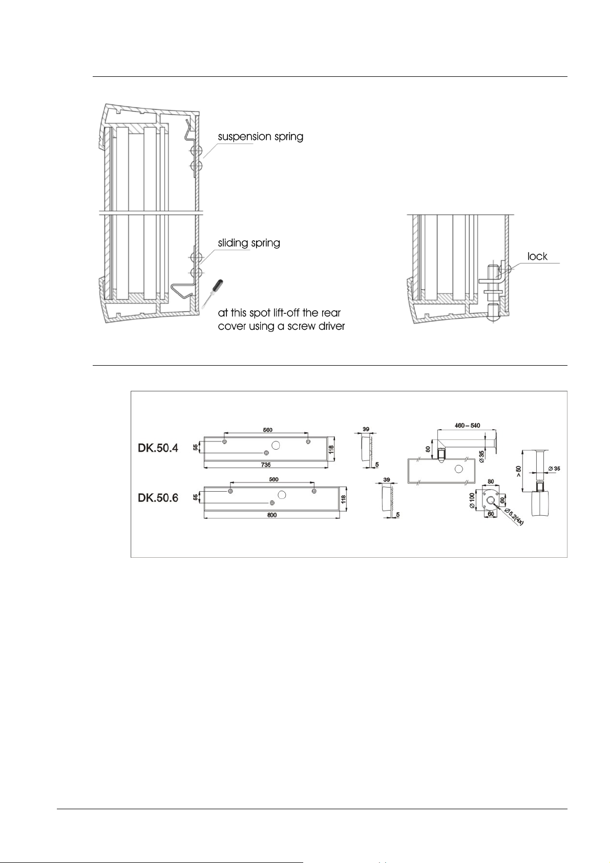
2.3 Dismantling of the clock rear cover
2.4 Assembly diagram
the anchorage plate does include the interconnecting terminal block, and provides
for an easy assembly in two steps
type length of the ceiling suspensions; 5, 10, 30, 50 cm
© MOBATIME 9 / 56 800444.05
Page 10
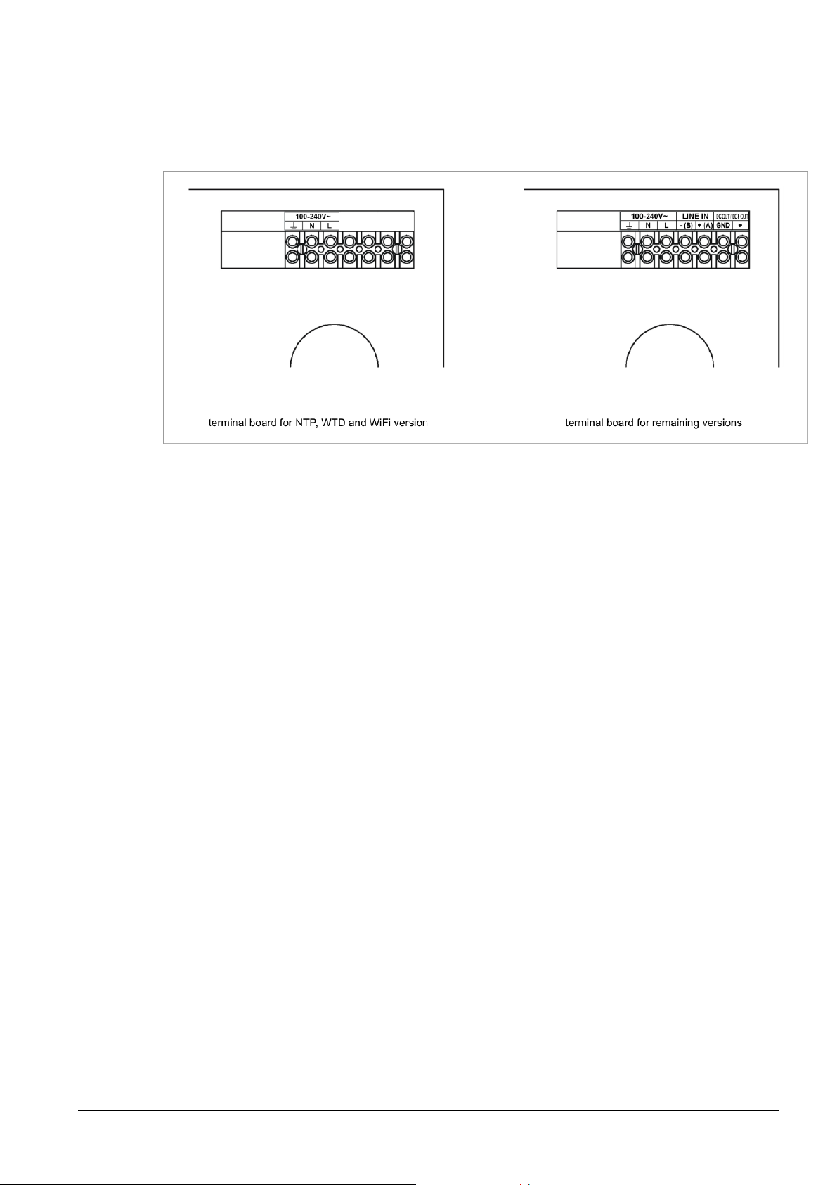
2.5 Connecting terminal block
© MOBATIME 10 / 56 800444.05
Page 11
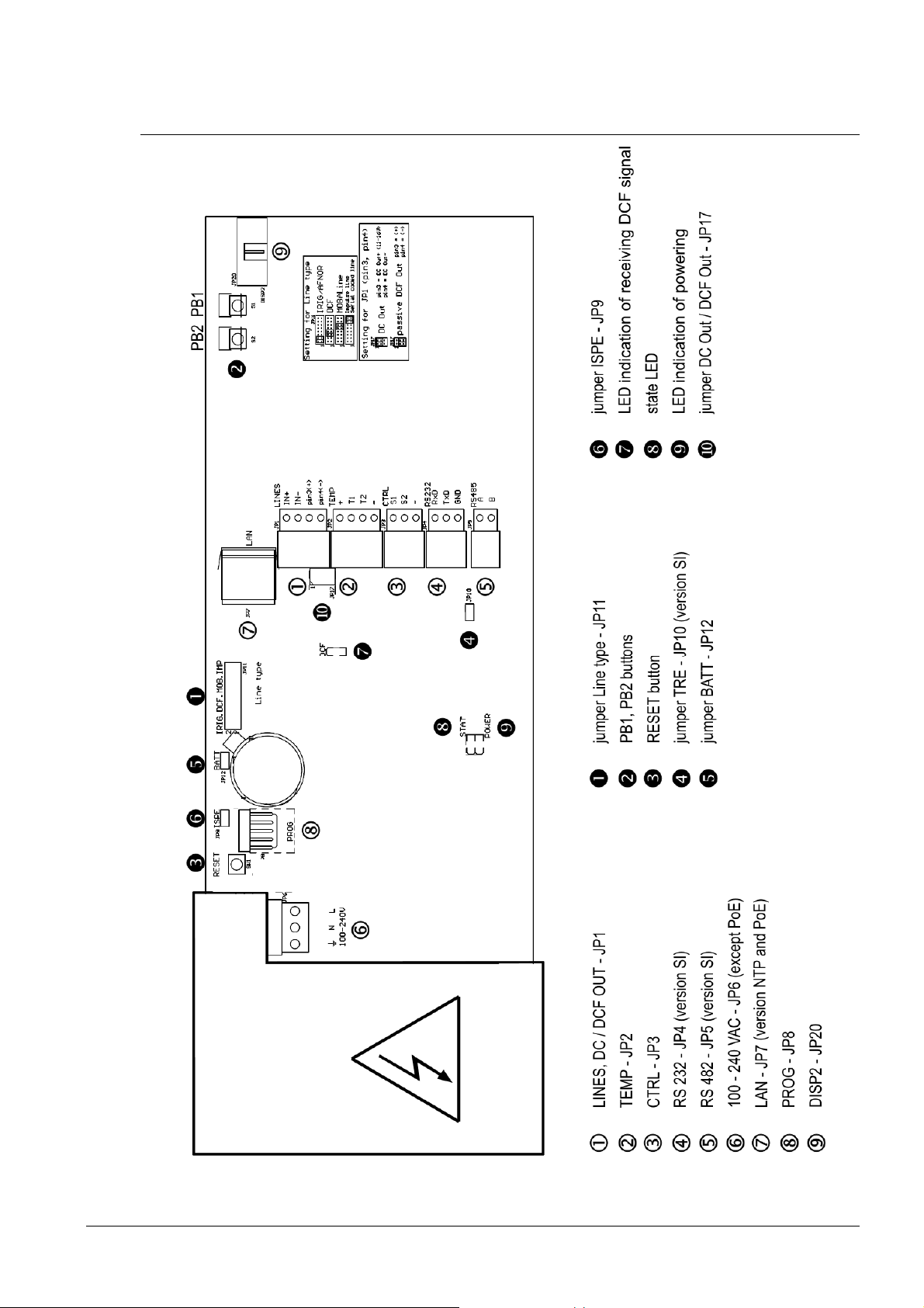
2.6 Control PCB
© MOBATIME 11 / 56 800444.05
Page 12
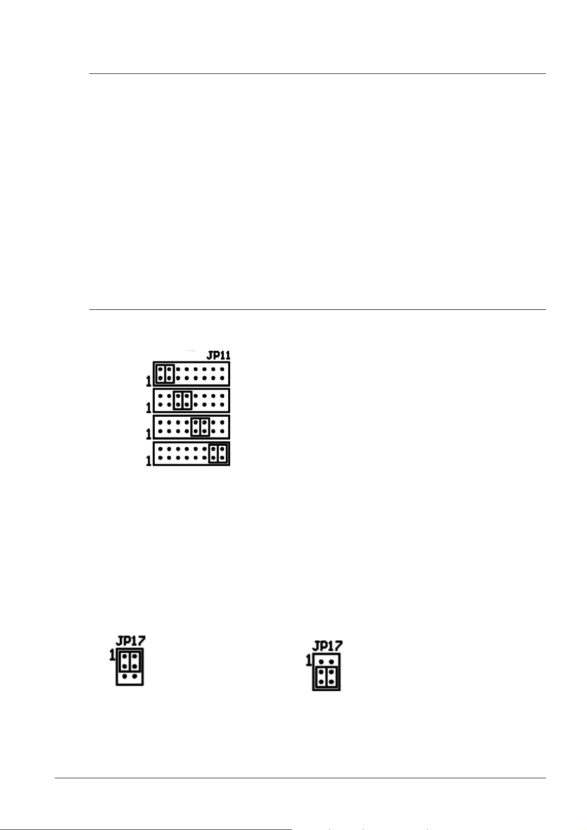
2.7 Function of the plug connectors
LINES, DC/DCF OUT – JP1 time signal inputs: The DCF/GPS receiver,
TEMP – JP2 connection of the temperature sensor(s)
CTRL – JP3 connection of the keyboard
RS232 – JP4 (optional) connection of the RS232 serial line
RS485 – JP5 (optional) connection of the RS485 serial line
100 – 240VAC – JP6 powering 100 - 240 VAC voltage
LAN - JP7 (optional) RJ45 10BaseT/100TX (IEEE 802.3)
PROG – JP8 clock firmware programming
DISP2 – JP20 connection of the second side
RELAY – JP21 (optional) switching contact (except DK.57.4)
2.8 Setting elements
Line type jumper – JP11 for the setting of the slave line type
polarized impulse line, MOBALine, MOBATIME
serial code, IRIG-B,
power supply output: DC OUT 11–19 V
or passive DCF current loop output
auto negotiation
IRIG / AFNOR
DCF
MOBALine
(Un)polarized impulse line
MOBATIME serial code
PB1, PB2 control pushbuttons
RESET the RESET button
TRE jumper – JP10 (optional) RS485 terminating resistor enable
BATT jumper – JP12 backup battery connection
ISPE jumper – JP9 invoking the firmware programming mode
DCF LED indication of receiving the DCF signal
STATE LED state indication
POWER LED power indication
jumper DC Out / DCF Out – JP17 Output signal setting on pins 3, 4
of the JP1 connector
DC Out
pin3 = DC Out + (11-19 V)
pin4 = DC Out -
passive DCF Out
pin3 = (+)
pin4 = (-)
© MOBATIME 12 / 56 800444.05
Page 13
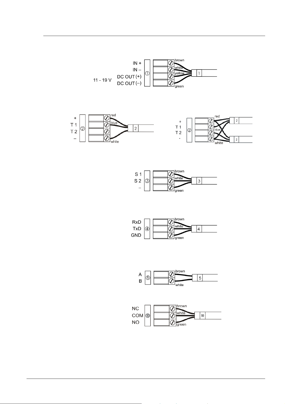
2.9 Connection of the cable ends
Installation LINES / DC OUT wire connection
TEMP wire connection – 1 or 2 thermometers
CTRL wire connection
RS232 wire connection
RS485 wire connection
RELAY connection
© MOBATIME 13 / 56 800444.05
Page 14
3 Control of the clock using keyboard or pushbuttons
The clock is adjusted and controlled using two pushbuttons located at the
upper side of the clock frame. If you use a keyboard for setting the stopwatch, use the
pushbuttons PB1 and PB2 for the clock setting.
Abbreviations used for the key strokes
PB1L, PB2L pushing the pushbutton for more than 1 second
PB1S, PB2S pushing the pushbutton for less than 1 second
Function of the pushbuttons in the “Clock“ mode
PB1S time correction to the whole minute (±30 sec)
PB2S changeover of the displayed items
Time -> date -> temperature -> stopwatch -> time
PB1L entry into the time and date setting mode
PB2L entry into the clock menu
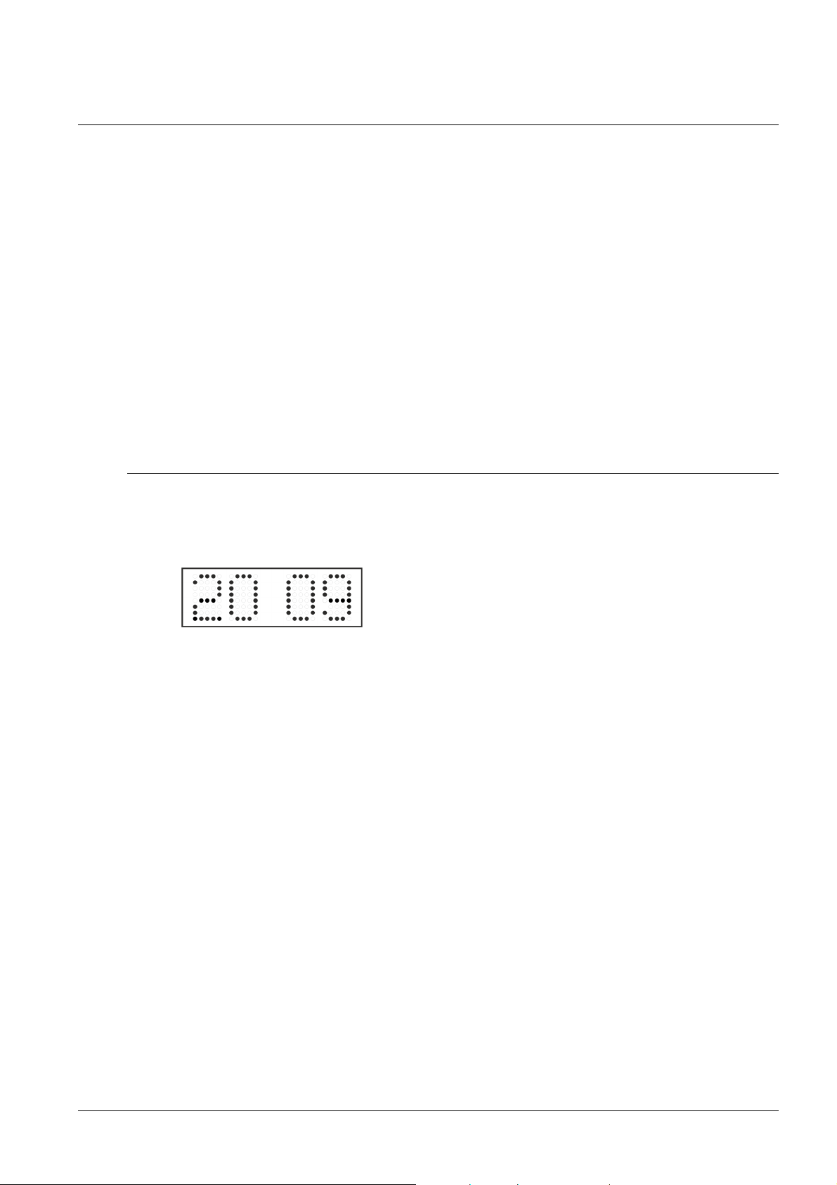
3.1 Setting of time and date
The setting of time and calendar date takes place in following steps: year – days
– months – hours – minutes. The entry into the time and date setting
mode occurs by pushing the PB1L pushbutton.
The display shows the following:
The item to be adjusted
is now blinking.
Move to another item by pushing the PB1S pushbutton. After having adjusted the
minutes and by pushing PB1S, the entered values are stored (the seconds are set to
zero) and the operation of the clock resumes. The clock returns into normal working
mode.
Note: When the time zone of displayed time and date (menu item P7) is set to the
values U1 – U7 or U, the entered time and date is taken as UTC.
Function of the pushbuttons in the “Time and date setting“ mode.
PB1S advancement to another item to be set up
PB2S increase of the item to be set up by 1
PB2L continuous increase of the current item
© MOBATIME 14 / 56 800444.05
Page 15
3.2 Menu for the setting of the clock parameters
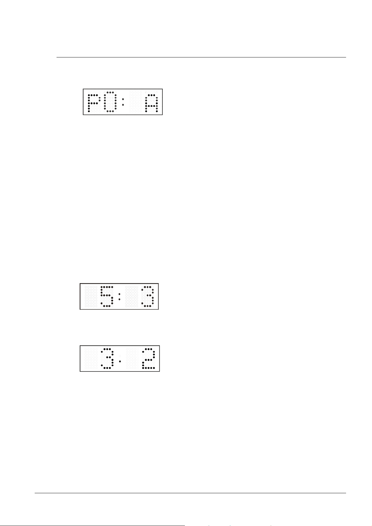
The entry into the parameter setup menu is done by pushing the PB2L button.
The display shows the following:
The item to be adjusted
is now blinking
The options for the parameter setup are shown in the clock menu table (chapter 5).
Function of the pushbuttons in the setup menu mode
PB1S storage of the current item and move to another menu item
PB1L storage of values and return into normal display mode, or entry
into the submenu, where it is permitted by the program
PB2S increase of the current item by 1
PB2L continuous increase of the current item
3.2.1 Submenu for user-specific setting of time constants for data
switchover
In menu item P2 (time constants for automatic switching over of values), set the value
U, then enter the submenu by pushing PB1L. The item to be set is blinking.
By pushing the PB2S button, the adjusted value is increased in steps of 1, by pushing
the PB2L button, the value will be continuously increased.
The display shows the following:
Enter the time constant for the display of time in seconds.
Push the PB1S button and enter the constant for date
display in seconds.
Push the PB1S pushbutton.
The display shows the following:
Enter the time constant for the display of temperature in
seconds. Push the PB1S pushbutton and enter the
constant for stopwatch display in seconds.
By pushing the PB1L button, the entered values are stored and the clock returns to the
menu item P2.
3.2.2 Submenu for setting of the user-specific time zone
Choose the value U in the item P7 (time zone displaying) in the clock menu, then enter
the submenu for setting the parameters of the user-specific time zone by pushing the
PB1L pushbutton. The item to be set is blinking.
By pushing the PB2S button, the adjusted value is increased in steps of 1, by pushing
the PB2L button, the value will be continuously increased.
© MOBATIME 15 / 56 800444.05
Page 16
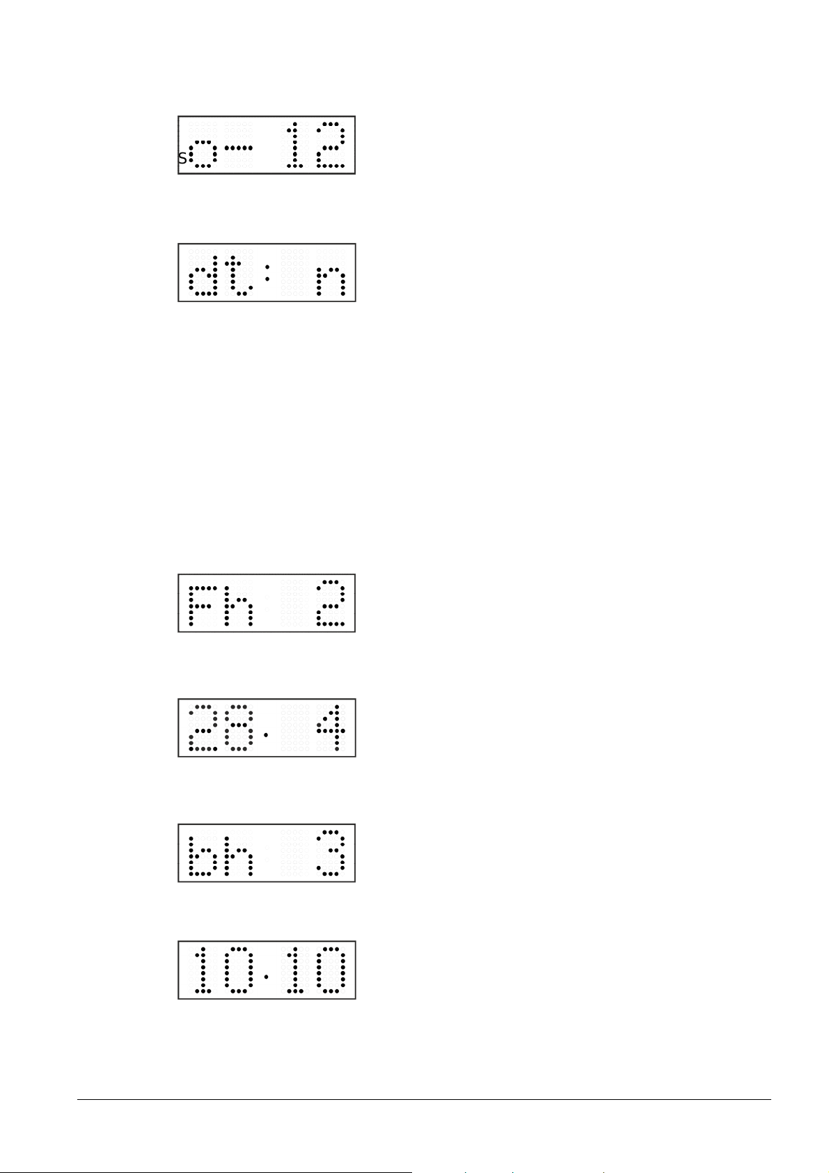
The display shows the following (example: -12 hours):
PB1S
PB1S
Enter the offset of the required time zone compared to
UTC time within -12 to +12 hours. Decimal point means
S
0.5 hour.
w
Switch over to setting the way of setting daylight saving time (DST) by pushing PB1S.
The display shows the following:
Possibility:
n – no DST is used
F – DST defined by fixed date
C – DST defined by calculated date
DST defined by fixed date and time
If the value F is set in the item dt:, enter the submenu for entering fixed date and time
by pushing PB1L.
The item to be set is blinking. By pushing the PB2S button, the adjusted value is
increased in steps of 1, by pushing the PB2L button, the value will be continuously
increased.
Symbols on the display:
Fh change to summer time; entry of the hour at daylight saving begins
bh shift back; entry of the hour at daylight saving ends
The display shows the following:
Enter the hour at which the daylight saving time begins.
Push PB1S.
The display shows the following:
Enter the day of the month. Push
in which the daylight saving time begins.
Push PB1S.
The display shows the following:
Adjust the hour at which the daylight saving time ends.
Push PB1S.
The display shows the following:
Enter the day of the month. Push
in which the daylight saving time ends.
. Enter the month
. Enter the month
The daylight saving time has been set to start on April 28that 2 o’clock and to
end on October 10that 3 o’clock in the example described above.
© MOBATIME 16 / 56 800444.05
Page 17

Save the setting by pushing PB1L and return to item dt:. Return to the clock menu item
P7 with another push of the PB1L button.
DST defined by calculated date
If the value C is set in item dt:, enter the submenu for the calculated date by pushing
PB1L.
The item to be set is blinking. By pushing PB2S, the adjusted value is increased in
steps of 1, by pushing the PB2L button, the value will be continuously increased.
Symbols in the display:
F change to summer time
b setting the time back
Scope of the setting:
Week 1. – 4., L (the last one), P (last but one)
and H (first after 15thday in the month)
Day of the week 1. – 7. (Mo – Su)
Month 1. – 12.
The display shows the following:
Enter the week in which the daylight saving time begins.
Push PB1S. Enter the day of the week at which the
daylight saving time begins.
Push PB1S.
The display shows the following:
Enter the month in which the daylight saving time begins.
Push PB1S. Enter the hour at which the daylight saving
time begins.
Push PB1S.
The display shows the following:
Enter the week in which the daylight saving time ends.
Push PB1S. Enter the day of the week at which the
daylight saving time ends.
Push PB1S.
The display shows the following:
Enter the month in which the daylight saving time ends.
Push PB1S. Enter the hour at which the daylight saving
time ends.
The daylight saving time has been set to start on the last Sunday in March at 2
o’clock and to end on the last Sunday in October at 3 o’clock in the above
described example.
Save the setting by pushing PB1L and return to the item dt:. Return to the clock menu
item P7 with another push of the PB1L button.
3.2.3 Submenu for network services configuration
Choose the value 2 or 3 in the item P19 (network work mode selection) in the clock
menu, then enter the submenu by pushing the PB1L pushbutton for configuring the
© MOBATIME 17 / 56 800444.05
Page 18
network services (Multicast support in unicast work mode, SNMP service, Telnet
service). The item to be set is blinking.
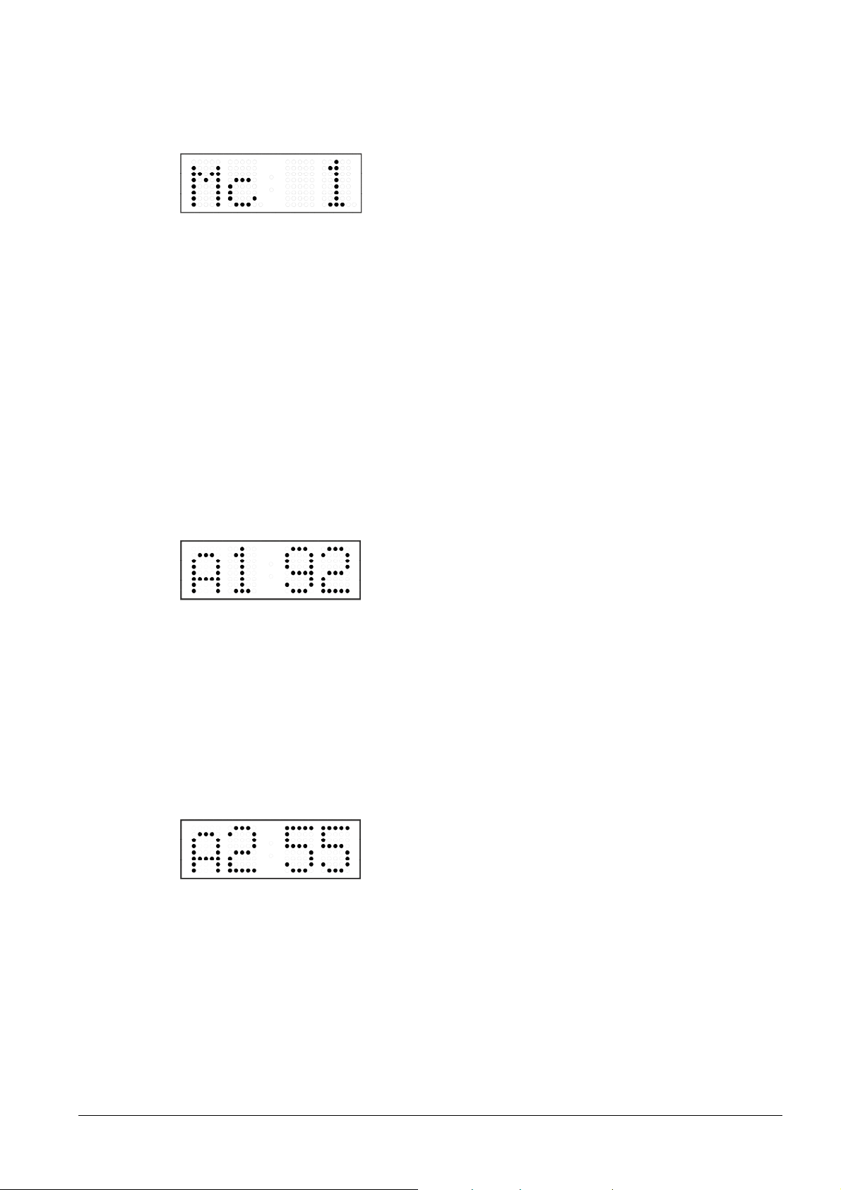
The display shows the following:
Set value1for enabling the multicast support in the
unicast work mode or value 0 for disabling it by pushing
the PB2S.
Switch to the next parameter – SNMP communication support by pushing the PB1S.
The display shows the Sn: 1. Set value 1 for enabling the SNMP support or value 0 for
disabling it by pushing the PB2S.
Switch to the next parameter – Telnet support by pushing the PB1S. The display
shows the tn: 1. Set value 1 for enabling the telnet support or value 0 for disabling it by
pushing the PB2S.
By pushing PB1L save the setting and return to item P19.
3.2.4 Manual setting of the IP address of the clock
Choose the item P20 in the main menu and push the PB1L button to enter the
submenu for setting the IP address. The item to be set is blinking.
By pushing PB2S, the adjusted digit value is increased in steps of 1, by pushing the
PB2L button, the value will be continuously increased.
The display shows the following:
Enter the four octets of the IP address step by step.
Switch to next digit or octet respectively by pushing the
PB1S. Octets are marked by letters A, b, C and d.
By pushing the PB1L button, the entered values are stored and the clock returns to the
menu item P20.
3.2.5 Manual setting of the subnet mask
Choose the item P21 in the main menu and push the PB1L button to enter the
submenu for setting the subnet mask. The item to be set is blinking.
By pushing PB2S, the adjusted value is increased in steps of 1, by pushing the PB2L
button, the value will be continuously increased.
The display shows the following:
Enter the four octets of the subnet mask step by step.
Switch to the next octet by pushing the PB1S button.
Octets are marked by letters A, b, C and d.
By pushing the PB1L button, the entered values are stored and the clock returns to the
menu item P21.
3.2.6 Manual setting of default gateway IP address
Choose item P22 in the main menu and push the PB1L button to enter the submenu
for setting the default gateway IP address. The item to be set is blinking.
By pushing PB2S the adjusted digit value is increased in steps of 1, by pushing the
PB2L button the value will be continuously increased.
© MOBATIME 18 / 56 800444.05
Page 19
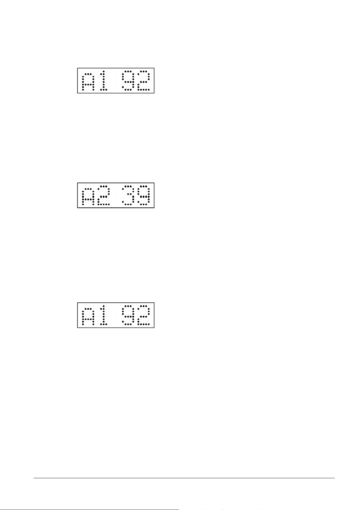
The display shows the following:
Enter the four octets of the gateway IP address step by
step. Switch to the next digit or octet respectively by
pushing the PB1S button. Octets are marked by letters A,
b, C and d.
By pushing the PB1L button, the entered values are stored and the clock returns to the
menu item P22.
3.2.7 Submenu for setting the multicast group address
Choose the menu item P23 and then enter the submenu by pushing the PB1L
pushbutton for setting the multicast group address. The item to be set is blinking.
By pushing the PB2S button, the adjusted digit value is increased in steps of 1; by
pushing the PB2L button, a continuous increase of the value takes place.
The display shows the following:
Enter the four octets of the IP address step by step.
Switch to the next digit or octet respectively by pushing
the PB1S button. Octets are marked by the letters A, b, C
and d.
By pushing the PB1L button, the entered values are stored and the clock returns to the
menu item P23.
3.2.8 Submenu for the setting of the NTP unicast synchronization
Choose the menu item P24 then enter the submenu by pushing the PB1L pushbutton
for setting the parameters of the NTP unicast synchronization. The item to be set is
blinking.
By pushing the PB2S button, the adjusted digit value is increased in steps of 1; by
pushing the PB2L button, the value will be continuously increased.
The display shows the following:
Set the four octets of the NTP server’s IP address step by
step. Switch to the next digit or octet respectively by
pushing the PB1S button. Octets are marked by letters A,
b, C and d.
After the last octet setting, set the constant x which determines the interval of
synchronization in seconds.
By pushing the PB1L button, the entered values are stored and the clock returns to the
menu item P24.
Note: Through the setup menu is possible to set only one NTP server IP address.
If more than one NTP server addresses were previously configured (using telnet or
MOBA-NMS tool), after opening the P24 submenu the IP address of currently active
NTP server is displayed. When the IP address was modified and the configuration is
saved using the setup menu, the IP address is stored to the definition of the first NTP
server, the other NTP server addresses are cleared including those defined by the NTP
server domain names.
3.2.9 Temperature description and time-zone names definition
(MENU page no. 2)
Choose the items R8 or R9 for temperature description or the items R10 – R14 for
time-zone names definition in the menu page no. 2 and push the PB1L button to enter
© MOBATIME 19 / 56 800444.05
Page 20
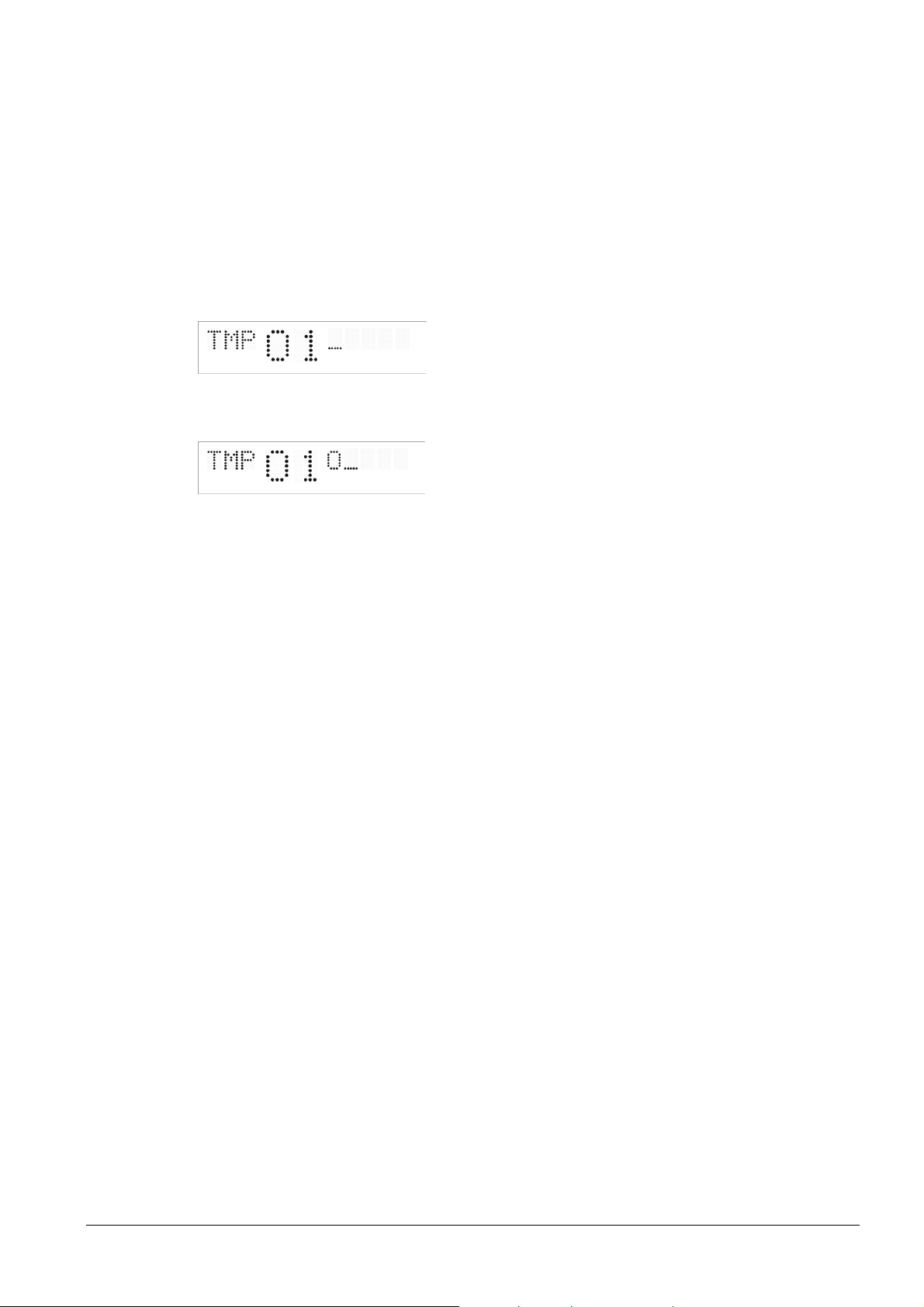
the submenu for text definition. After entering the edit mode the cursor is blinking. By
pushing PB2S available characters are listed (see chapter 16 for character set table).
Press PB1S to move to next position and select next character. For fast listing through
the characters the PB2L push can be used.
The description of temperature can have up to 5 characters, the time-zone name up to
8.
Ex.: Editing of the text – temperature no. 1 description “OUT”
In MENU page no. 2 select the item R8 by pressing PB1S. By pressing PB2S set the
value to Y. By pressing PB1L enter the text editing mode.
The display shows the following:
The cursor blinks on the first position, by pressing PB2S set the character O, press the
PB1S and the display shows:
-> with PB2S set U -> PB1S -> the cursor blinks on the 3rd position -> with PB2S set T
-> pushing the PB1S two times move to the last character -> with next push of PB1S
save the edited text and move to next MENU item (R9 – temperature no. 2 description).
For closing the menu mode move to item R0 and press PB1L. The clock returns to
normal mode.
© MOBATIME 20 / 56 800444.05
Page 21
4 Control of the clock using IR remote control
A 2-digit address is assigned to the clock. With the IR remote control the clock can be locked.
The setting of time, date and the clock parameters can only take place at clocks in an
unlocked state.
Function of the pushbuttons in normal display mode
pushing F1 + entry of 2-digit address, unlock the clock with the
using numerical pushbuttons corresponding address
holding down F1 button unlock all clocks within the reach of the IR
beam of the remote control unit
holding down F2 button lock all clocks within the reach of the IR
beam of the remote control unit
holding down F3 button display the address of all locked clocks within
the reach of the IR beam of the remote control
Function of the pushbuttons in the “Clock“ operation mode
SET entry into the time and date setting mode
The + button button brightness increase (not applicable when
P0 is set to A)
The - button button brightness decrease (not applicable when
P0 is set to A)
CLOCK visualization of time + date
DATE visualization of
TEMP visualization of time + temperature
TIMER visualization of stopwatch
MENU entry into the menu of setting of clock
parameters
CLR time correction to the whole minute (±30 sec)
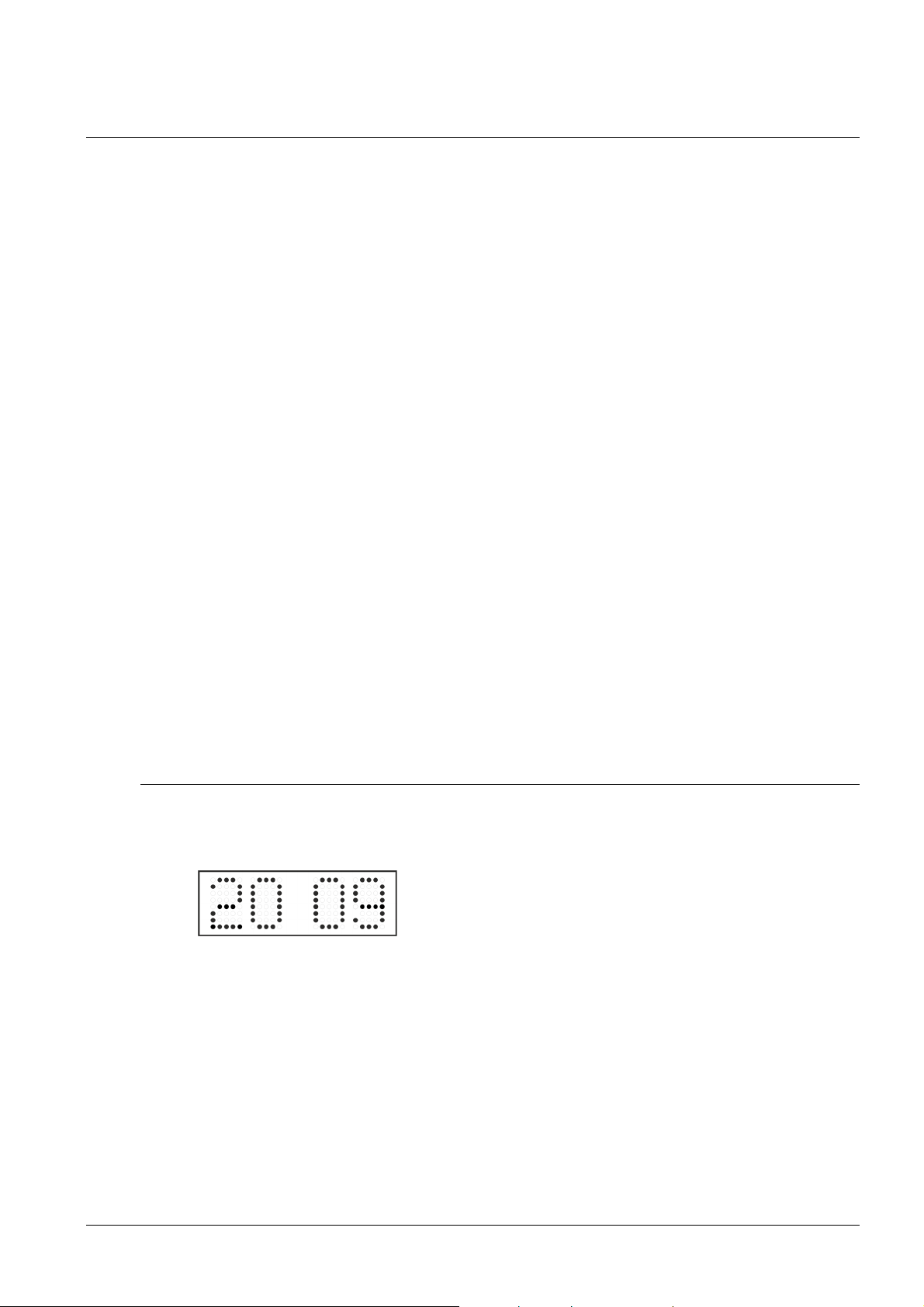
4.1 Setting of time and date
The time and date values are adjusted in the following sequence: year – day – month –
hours – minutes. By pushing the SET button, enter the time and date setting mode.
The display shows the following:
After having set up the minutes the value is blinking. By pushing the OK button the
value is stored (with seconds reset to zero) and the clock operation resumes. The clock
returns into normal working mode.
Note: When the time zone of displayed time and date (menu item P7) is set to the
values U1 – U7 or U, the entered time and date is taken as UTC.
The item to be set is blinking.
© MOBATIME 21 / 56 800444.05
Page 22
Function of the pushbuttons in the “Time and date setting“ mode
The + pushbutton increase of the value adjusted, in steps of 1
The – pushbutton decrease of the value adjusted, in steps of 1
Holding down the + button continuous increase of the value set up
Holding down the – button continuous decrease of the value set up
ESC return into normal display mode, without storage of the
data
>> move to next parameter
<< move to previous parameter
CLR entry of zero or minimum value
OK storage of values set up and return into normal working
mode, followed with seconds reset
Pushbuttons 0–9 entry of the corresponding numerical value
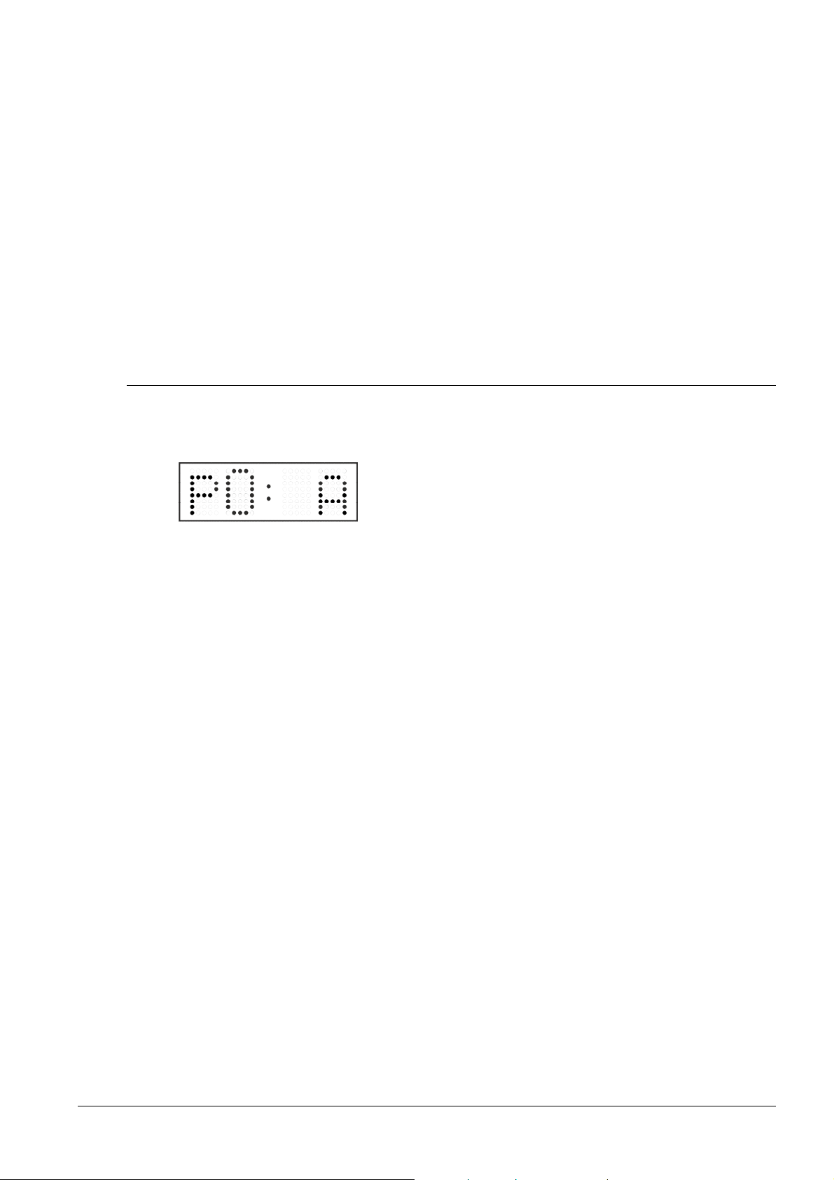
4.2 Menu for the setting of the clock parameters
The entry into the menu no. 1 for the setting of the clock parameters is done by
pushing the MENU button.
The display shows the following:
The item to be set is blinking.
The options for the parameters to be set up are shown in the menu no. 1 table on page
(chapter 5).
Function of the pushbuttons in the “MENU“ mode
>> move to next menu item
<< move to previous menu item
The + button increase of the value adjusted,
in steps of 1
The - button decrease of the current value,
in steps of 1
Holding down the + button continuous increase of the value set up
Holding down the – button continuous decrease of the value set up
ESC return into the normal working mode,
without storing the modified items
OK storing of the modified items and return
into the normal working mode
SET enter the sub-menu, where it is possible
Pushbuttons 0–9 entry of the corresponding numerical value
F1 menu page no. 1 – basic clock parameters
F2 menu page no. 2 – display parameters
Note: During entering the numbers in the octets of the IP addresses the editing to the
next digit moves automatically.
4.2.1 Submenu for user-specific setting of time constants for data
switchover
In menu item P2 (time constants for automatic switching over of values) set value U,
then enter the submenu by pushing the SET button. The item to be set is blinking.
© MOBATIME 22 / 56 800444.05
Page 23
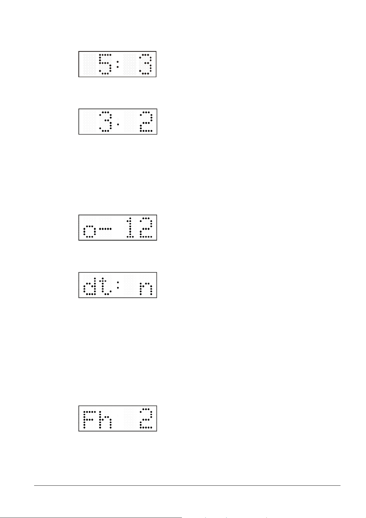
The display shows the following:
Options:
Enter the constant for time display, in seconds. Push the
>> button and enter the time constant for the display of
date, in seconds.
Push SET.
The display shows the following:
Enter the time constant for the display of temperature, in
seconds. Push the >> button and enter the time constant
for the display of stopwatch, in seconds.
By pushing OK, the entered values are stored and the clock returns to the menu item
P2. Return to the item P2 without storing by pushing ESC.
4.2.2 Submenu for setting of the user-specific time zone
Choose the value U in the item P7 (time zone displaying) in clock menu, then by
pushing the SET enter the submenu for setting the parameters of the user-specific time
zone. The item to be set is blinking.
The display shows the following (example: -12 hours):
Enter the offset of the required time zone compared to
UTC time within -12 to +12 hours. Decimal dot means 0,5
hour.
Switch over to setting the way of setting daylight saving time (DST) by pushing >>.
The display shows the following:
n – no DST is used
F – DST defined by fixed date
C – DST defined by calculated date
Return to the clock menu item P7 by pushing the OK button.
DST defined by entering fixed date and time
If the value F is set in item dt:, by pushing SET enter the submenu for entering fixed
date and time. The item to be set is blinking.
Symbols on the display:
Fh change to summer time; entry of the hour at daylight saving begins
bh shift back; entry of the hour at daylight saving ends
The display shows the following:
Enter the hour at which the daylight saving time begins.
Push >>.
© MOBATIME 23 / 56 800444.05
Page 24
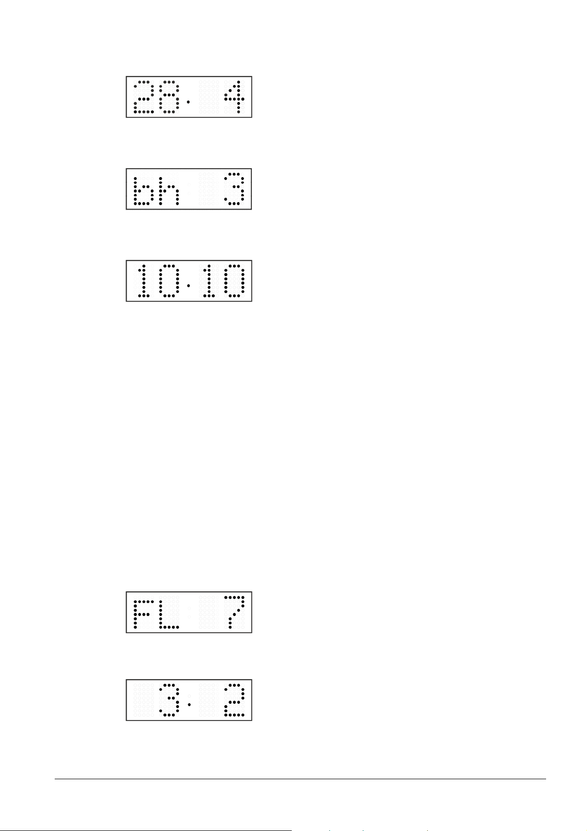
The display shows the following:
Enter the day of the month. Push>>. Enter the month in
which the daylight saving time begins.
Push >>.
The display shows the following:
Enter the hour at which the daylight saving time ends.
Push >>.
The display shows the following:
Enter the day of the month. Push>>. Enter the month in
which the daylight saving time ends.
The daylight saving time has been set to start on April 28that 2 o’clock and end
on October 10that 3 o’clock in the above described example.
Save the setting and return to item dt: by pushing OK, return to the clock menu item
P7 by another push of the OK button.
By entering calculated date
If the value C is set in item dt:, by pushing SET enter the submenu for the calculated
date. The item to be set is blinking.
Symbols in the display:
F change to summer time
b setting the time back
Scope of the setting:
Week 1. – 4., L (the last one), P (last but one)
and H (first after 15thday in the month)
Days of the week 1. – 7. (Mo – Su)
Month 1. – 12.
The display shows the following:
Enter the week in which the daylight saving time begins.
Push >>. Enter the day of the week in which the daylight
saving time begins.
Push >>.
The display shows the following:
Enter the month in which the daylight saving time begins.
Push >>. Enter the hour in which the daylight saving time
begins.
Push >>.
© MOBATIME 24 / 56 800444.05
Page 25
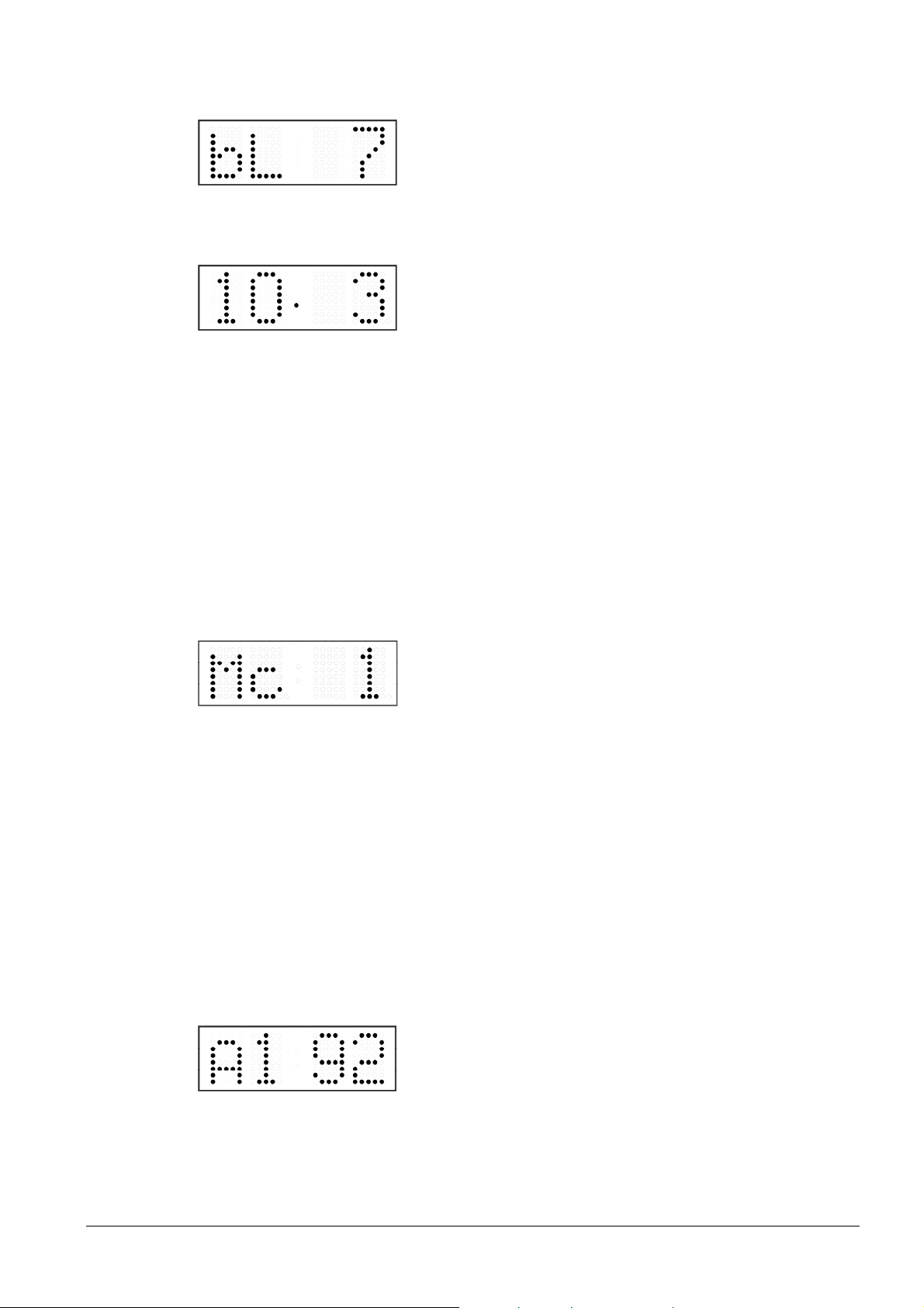
The display shows the following:
Enter the week in which the daylight saving time ends.
Push >>. Enter day of the week in which the daylight
saving time ends.
Push >>.
The display shows the following:
Enter the month in which the daylight saving time ends.
Push >>. Enter the hour in which the daylight saving time
ends.
The daylight saving time has been set to start on last Sunday in March at 2
o’clock and end on last Sunday in October at 3 o’clock in the above described
example.
By pushing OK save the setting and return to item dt:. Another push of the OK button
returns to the clock menu item P7.
4.2.3 Submenu for network services configuration
Choose the value 2 or 3 in the item P19 (network work mode selection) in the clock
menu, then enter the submenu by pushing the SET for configuring the network services
(Multicast support in unicast work mode, SNMP service, Telnet service). The item to be
set is blinking.
The display shows the following:
Set value1for enabling the multicast support in the
unicast work mode or value 0 for disabling it.
Switch to the next parameter – SNMP communication support by pushing the >>. The
display shows the Sn: 1. Set value 1 for enabling the SNMP support or value 0 for
disabling it.
Switch to the next parameter – Telnet support by pushing the >>. The display shows
the tn: 1. Set value 1 for enabling the telnet support or value 0 for disabling it.
By pushing OK, the entered values are stored and the clock returns to the menu item
P19. By pushing ESC, the clock returns to P19 without saving.
4.2.4 Manual setting of the IP address of the clock
Choose the item P20 in the main menu and push the SET button to enter the submenu
for setting the IP address. The item to be set is blinking.
The display shows the following:
Enter four octets of the IP address step by step. Switch to
another octet by pushing the << and >> buttons. Octets
are marked by letters A, b, C and d.
By pushing OK, the entered values are stored and the clock returns to the menu item
P20. By pushing ESC the clock returns to P20 without storing.
© MOBATIME 25 / 56 800444.05
Page 26
4.2.5 Manual setting of the subnet mask
Choose the item P21 in the main menu and push the SET button to enter the submenu
for setting the subnet mask. The item to be set is blinking.
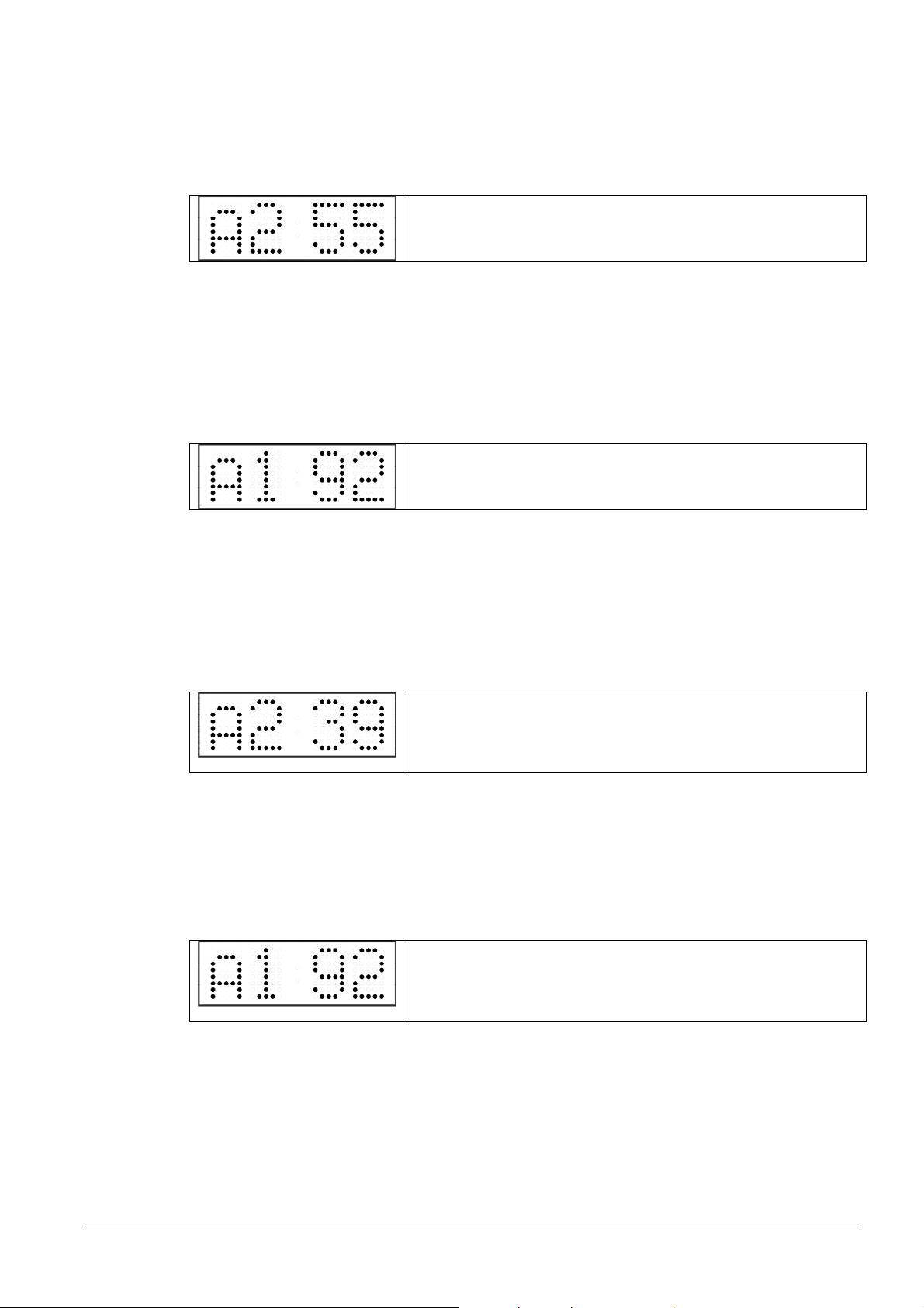
The display shows the following:
Enter the four octets of the subnet mask step by step.
Switch to another octet by pushing the << and >> buttons.
Octets are marked by letters A, b, C a d.
By pushing OK, the entered values are stored and the clock returns to the menu item
P21. By pushing ESC, the clock returns to P21 without saving.
4.2.6 Manual setting of default gateway IP address
Choose the item P22 in the main menu and push the SET button to enter the submenu
for setting the default gateway IP address, the item to be set is blinking.
The display shows the following:
Enter the four octets of the gateway IP address step by
step. Switch to another octet by pushing the << and >>
buttons. Octets are marked by letters A, b, C and d.
By pushing OK, the entered values are stored and the clock returns to the menu item
P22. By pushing ESC, the clock returns to P22 without saving.
4.2.7 Submenu for setting the multicast group address
Choose the menu item P23 and then enter the submenu by pushing the SET for setting
the multicast group address. The item to be set is blinking.
The display shows the following:
Enter the four octets of the IP address step by step.
Switch to the next digit or octet respectively by pushing
the >> button. Octets are marked by the letters A, b, C
and d.
By pushing OK, the entered values are stored and the clock returns to the menu item
P23. By pushing ESC, the clock returns to P23 without saving.
4.2.8 Submenu for the setting of the NTP unicast synchronization
Choose the menu item P24 and then enter the submenu by pushing the SET for setting
the parameters of the NTP unicast synchronization. The item to be set is blinking.
The display shows the following:
Set the four octets of the NTP server’s IP address step by
step. Switch to the next digit or octet respectively by
pushing the >> button. Octets are marked by letters A, b,
C and d.
After the last octet setting, set the constant x which determines the interval of
synchronization in seconds.
By pushing OK, the entered values are stored and the clock returns to the menu item
P24. By pushing ESC, the clock returns to P24 without saving.
© MOBATIME 26 / 56 800444.05
Page 27
Note: Through the setup menu is possible to set only one NTP server IP address.
If more than one NTP server addresses were previously configured (using telnet or
MOBA-NMS tool), after opening the P24 submenu the IP address of currently active
NTP server is displayed. When the IP address was modified and the configuration is
saved using the setup menu, the IP address is stored to the definition of the first NTP
server, the other NTP server addresses are cleared including those defined by the NTP
server domain names.
4.2.9 Temperature description and time-zone names definition
(MENU page no. 2)
Choose the items R8 or R9 for temperature description or the items R10 – R14 for
time-zone names definition in the menu page no. 2 and push the SET button to enter
the submenu for text definition. After entering the edit mode the cursor is blinking. By
pushing + or – available characters are listed (see chapter 16 for character set table).
Press >> to move to next position and select next character. For fast listing through the
characters keep the + or – buttons depressed. Insert a space by pushing CLR,.
The description of temperature can have up to 5 characters, the time-zone name up to
8.
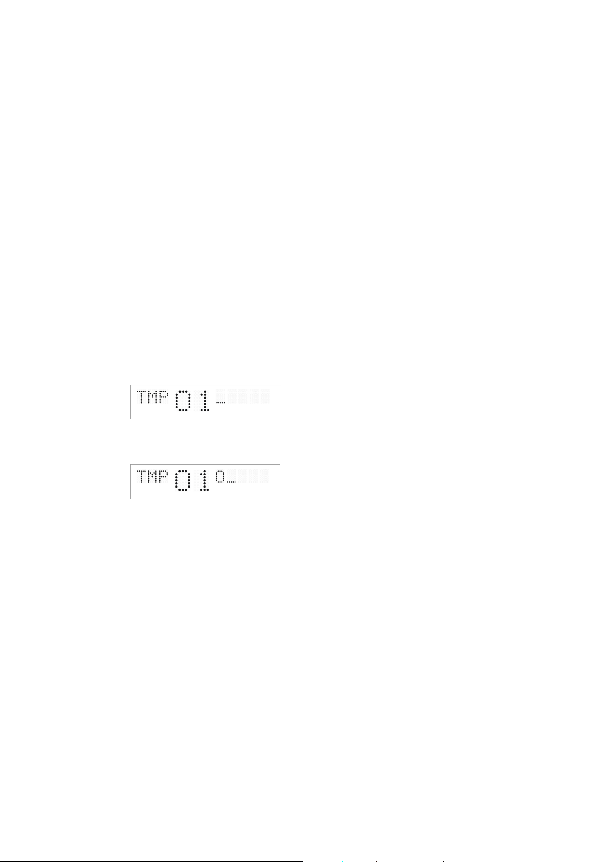
Ex.: Editing of the text – temperature no. 1 description “OUT”
In MENU page no. 2 select the item R8 by pressing >>. By pressing + or – set the
value to Y. By pressing SET enter the text editing mode.
The display shows the following:
The cursor blinks on the first position, by pressing + set the character O, press the >>
and the display shows:
with + set U >> the cursor blinks on the 3rd position with + set T pushing
the OK button saves the edited text and move back to MENU item R8.
Set other parameters in MENU and by pressing OK button return to normal mode.
© MOBATIME 27 / 56 800444.05
Page 28
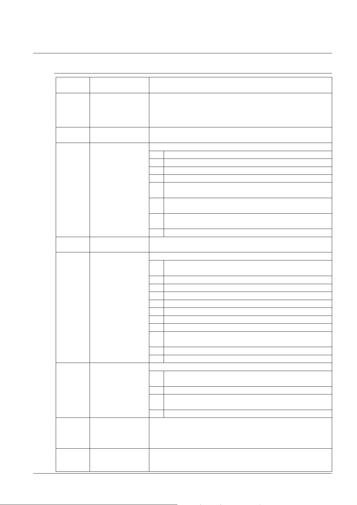
5 The clock menu table
Program
Function
Scope of the values
, A
24 h,
1
A
1
5.1 Menu page no. 1 – basic clock parameters
item
P0 Display brightness
(default values are printed in bold)
1-30
(automatic adjustment, without the possibility of
changing in normal display mode)
The maximum brightness setting in manual mode can reduce the life cycle
of the LED displays in the long run. We recommend leaving the brightness
control to "auto" mode (default value).
P1 Time display
12 h
format
P2 Time constants for
automatic data
switching over
-6, U,0
1 continuous display of time + date
2 continuous display of date + temperature
3 continuous display of time zone
4 continuous display of stop watch
5 display sequence: time + date 6 sec, time +
temperature 3 sec.
6 display sequence: time + date 8 sec, time +
temperature 3 sec, time zone 3 sec.
U* time constants set up by user, in seconds for each
specific displayed data
0 automatic switching over disabled
3 Time zone of
0 - 64,A(automatically)
synch. source
P4 Type of
synchronization
source
1 - 10,A(automatically)
auto detection, applicable for: DCF, the Mobatime serial
code, MOBALine, WTD, IRIG-B or NTP
1 autonomous operation without synchronization
2 synchronization by DCF signal
3 the MOBATIME serial code
4 MOBALine
5 24 V DC impulses, at minute intervals
6 24 V DC impulses at half minute intervals
7 24 V DC impulses at second intervals
8 DCF-FSK, IRIG-B Standard, IRIG-B 123, IRIG-B DIEM,
AFNOR A, AFNOR C
9 RS232
10 RS485
P5 Impulse line
processing mode
-4
1 polarized impulses, synchronization and time
adjustment
2 polarized impulses; time synchronization only
3 non-polarized impulses, synchronization and time
adjustment
4 non-polarized impulses; time synchronization only
P6 Time zone for
MOBALine or time
zone server
1-20,0(off) – for MOBALine synchronization
or
1-15, 0 (off) – for NTP synchronization
MOBATIME
P7 Time zone of
displayed time and
0 - 64,A(automatically), U* (user time zone)
U1-U7 (preconfigured time zone entry by MOBA-NMS)
date
© MOBATIME 28 / 56 800444.05
Page 29
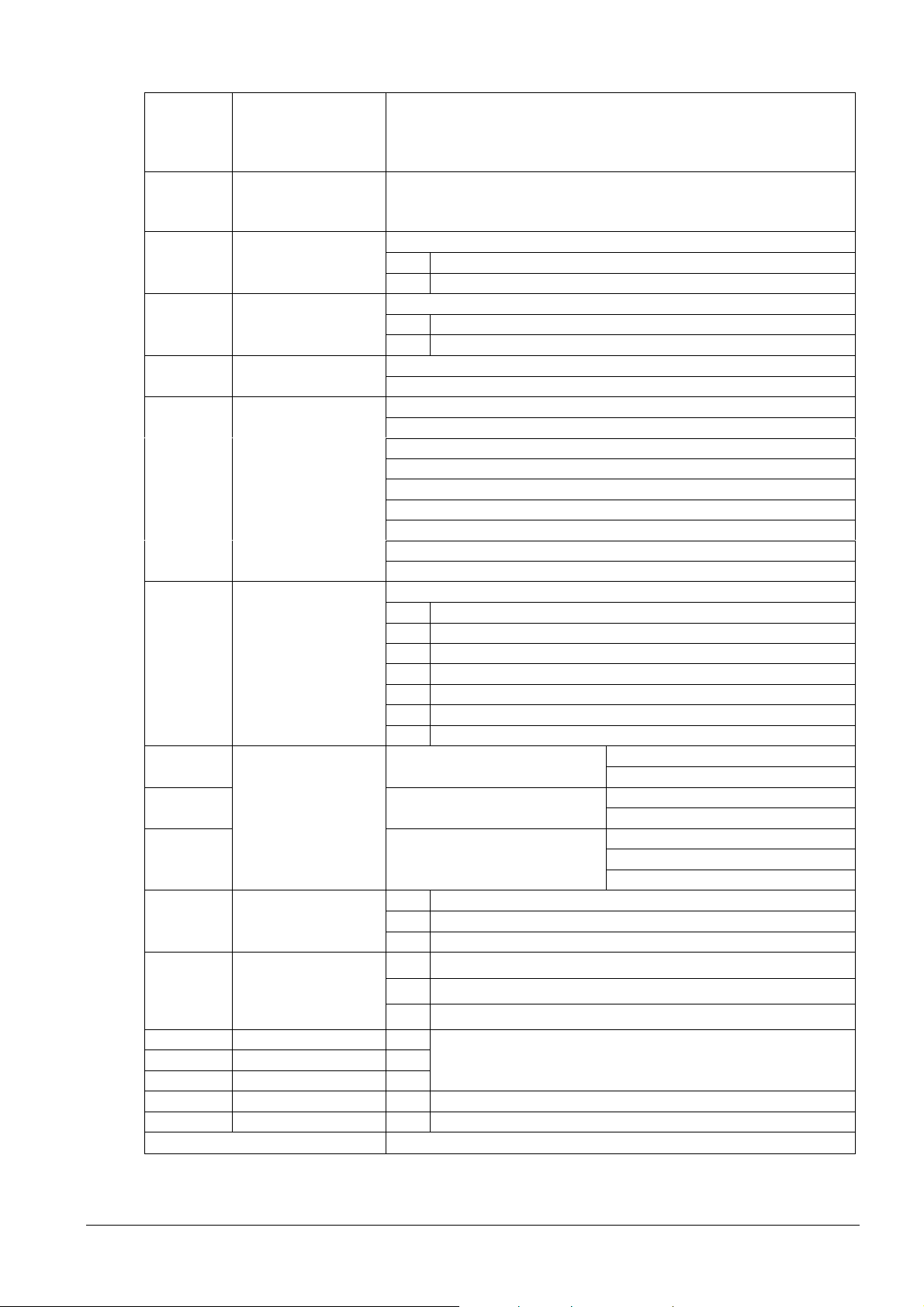
P8 Clock address for
99
1
2
°C
1
4
7
1
E
0
3
*
IR remote control
and the serial
1-
0-31, L (listen only) at SI version
0-15 - at WTD version
protocols
P9 IR controller
autolock
1-60,U("automatic lock" is OFF)
Time in minutes for "automatic lock" since the last
depression of button on the IR unit
P10 Time format
display
-2
1 time with leading zero
2 time without leading zero
P11 Date format
display
11 date with leading zero
2 date without leading zero
P12 Temperature
format display
P13 Protocol for
RS232 and RS485
communication
°F
- IF482
2 - Supervised RS485
3 - DK master
4 - DK slave
5 – TP … RS485 master
6 – TP … RS485 listener
7 – no function
8 – T741x master
9 – T741x listener
P14 Modulation speed
for RS232 and
RS485
1-7
1 1 200 Baud
2 2 400 Baud
3 4 800 Baud
9 600 Baud
5 19 200 Baud
6 38 400 Baud
7 57 600 Baud
P 15 Transmission
Number of data bits 8
parameters for
P 16 Number of stop bits
RS232 and RS485
2
P 17 Parity n no parity
o odd
even
P 18 Special operation
mode
normal mode
1 special mode 1
2 special mode 2
P19 Network operation
mode
P20 IP address IP*
P21 Subnet mask Su*
P22 Gateway Gt*
NTP and PoE: multicast (without IP address)
1
WiFi: initial network MOBA – WIFI, IP address assigned by DHCP
NTP and PoE: unicast – network param. defined manually
2*
WiFi: wireless network defined by user, IP address set manually
NTP and PoE: unicast – network param. defined by DHCP
WiFi: wireless network defined by user, IP address assigned by DHCP
edit network parameters in manual setting mode or
display parameters assigned by DHCP
P23 Multicast addr. Mc* setting of multicast group address
P24
Unicast NTP addr Uc* setting of NTP unicast server address
SW version r_._(e.g.: r2.68)
Note: * possibility to enter the submenu
Items P19 to P24 available in NTP, PoE and WiFi variants only
© MOBATIME 29 / 56 800444.05
Page 30
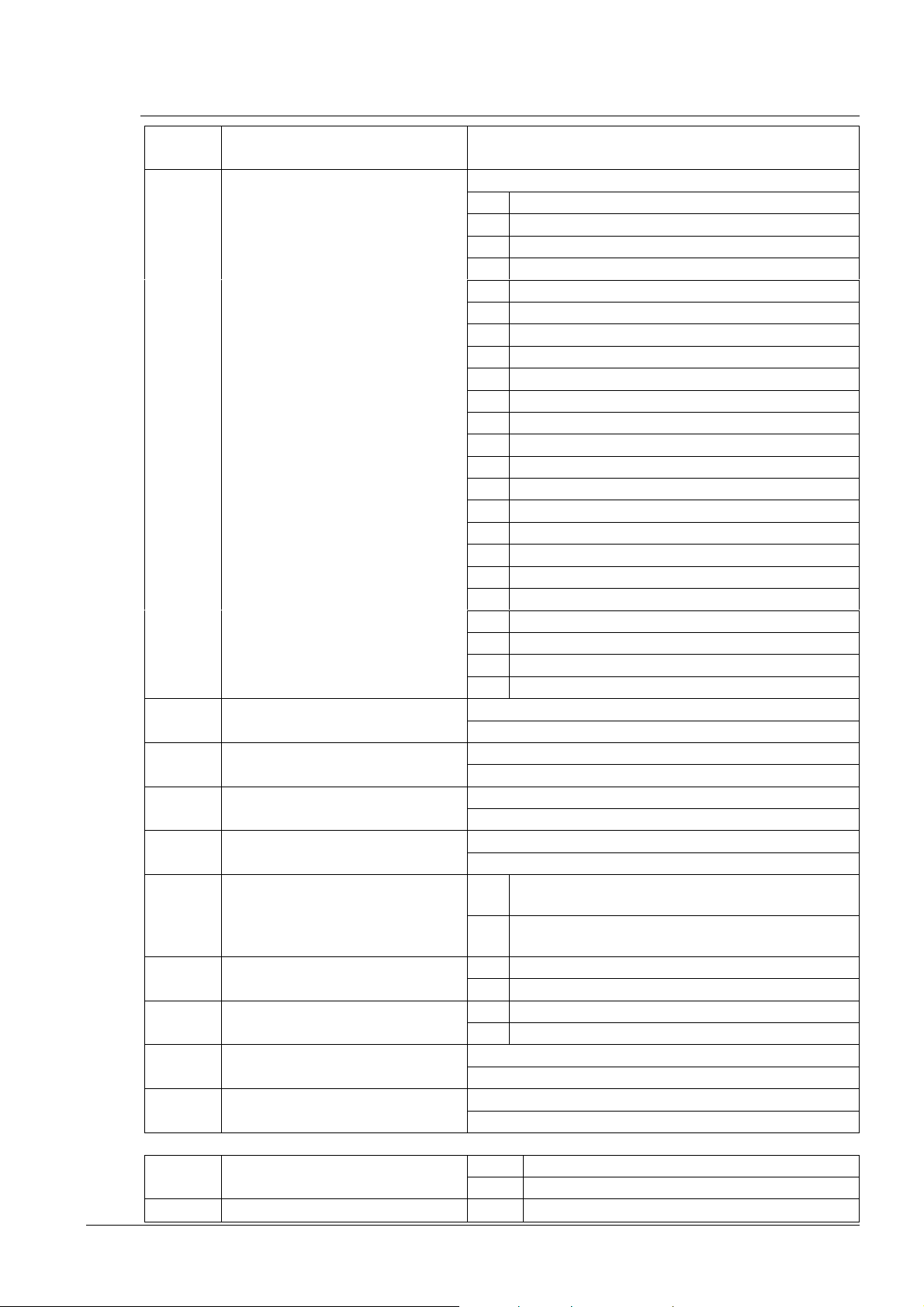
5.2 Menu page no. 2 – display parameters
Progra
Function
Scope of the values
N
°C
N
A
1
N
N
N
N
m item
R0 First language selection
(also language used for
weekday name in time
zone displaying)
(default values are printed in bold)
23 languages to choose from
1 Czech
2 Slovak
3 English
4 German
5 French
6 Italian
7 Russian
8 Spanish
9 Portuguese
10 polish
11 Magyar
12 Dutch
13 Danish
14 Finnish
15 Swedish
16 Norwegian
17 Serbian (Latin)
18 Serbian (Cyrillic)
19 Croatian
20 Slovenian
21 Romanian
22 Bulgarian
23 Greek
R1 Second language selection 23 languages + option N – “none”
1 – 23,
R2 Temperature units for second
selected language
°F
R3 Third language selection 23 languages + option N – “none”
1-23,
R4 Temperature units for second
selected language
R5 Language switch mode for
°C
°F
all languages
automatic language switching
over in one display alternating
S single language
cycle
R6 Number of characters used for
weekday names
R7 Weekday and month display
format
2 two characters
3
three characters
all capitals
2 first capital, others small
R8 Display of description for first
measured temperature
Y*
R9 Display of description for
second measured temperature
Y*
© MOBATIME 30 / 56 800444.05
R10 World time – Time Zone 1
R11 World time – Time Zone 2
option N – “disabled”
0-64* 0-64 according to time zone table
option N – “disabled”
Page 31
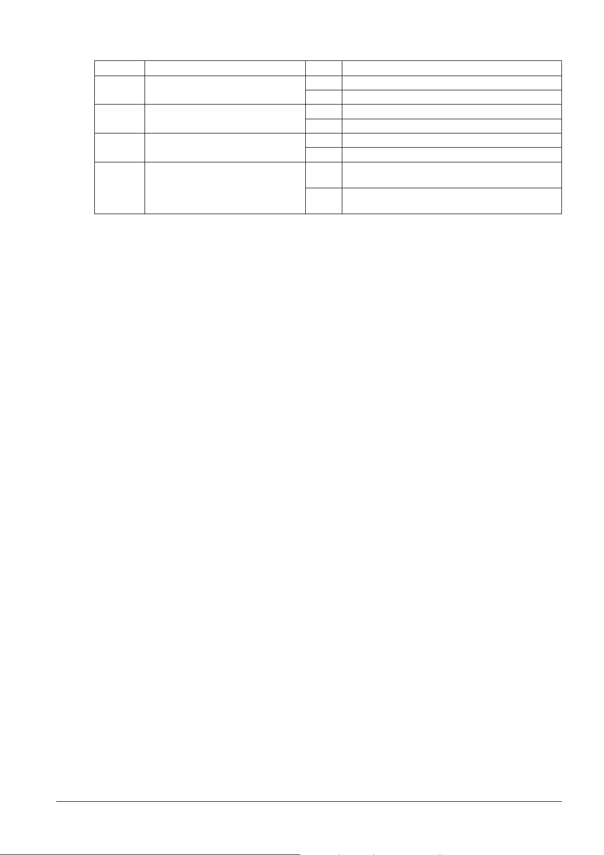
0-64* 0-64 according to time zone table
N
N
N
A
R12 World time – Time Zone 3
option N – “disabled”
0-64* 0-64 according to time zone table
R13 World time – Time Zone 4
option N – “disabled”
0-64* 0-64 according to time zone table
R14 World time – Time Zone 5
option N – “disabled”
0-64* 0-64 according to time zone table
R15 World time switch mode for
all world time zones
automatic time zone switching
over in one display alternating
S single world time zone
cycle
Note: * possibility to enter the submenu for description text definition of temperature (up to 5
characters) or time zone name definition (up to 8 characters)
© MOBATIME 31 / 56 800444.05
Page 32
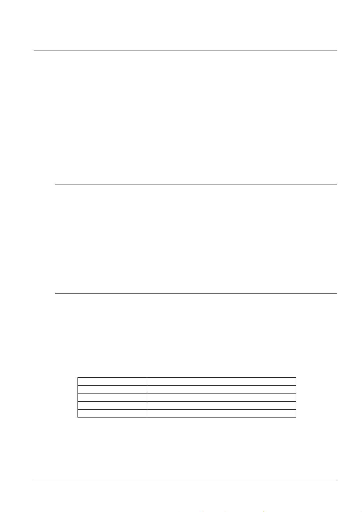
6 Control of the stopwatch via keyboard
The operation of the stopwatch is controlled and the device is adjusted using three
pushbuttons on the connected keyboard. The keyboard cable must be connected to the CTRL
plug connector.
Abbreviations used for the key strokes
PB1L, PB2L pushing of the pushbutton for a period of
more than 1 second
PB1S, PB2S, PB3S short-time pushing of the pushbutton
Function of the pushbuttons in the “Stopwatch“ mode
PB2S indication switch-over:
time - date - temperature - stopwatch - time
PB2L stopwatch menu
PB3S, PB1S, PB1L according to the stopwatch mode setup
6.1 The stopwatch menu
The stopwatch menu is entered by pushing the PB2L pushbutton (stopwatch must be
displayed). The parameter adjustment is to be performed according to the menu table
(chapter 8).
Function of the pushbuttons in the “Stopwatch Menu“ mode
PB1S move to another menu item
PB1L storage of the parameters; return to the stopwatch display mode when
counting up from zero; or entry into the initial time setting mode when
counting down
PB2S increase of the current value, in steps of 1
PB2L continuous increase of current value
6.2 Setting of the initial time for counting down
When counting down is selected, the initial time setting mode is entered from the
stopwatch MENU or directly from the “Stopwatch” display mode by pushing the PB1L
button. The item to be set is blinking.
By pushing the PB2S button is the adjusted value increased in steps of 1, by pushing
the PB2L button will be the value continuously increased. By pushing PB1S move to
the next item. By pushing the PB1L save the setting and return to “Stopwatch” display
mode.
Enter the data in the following order depending on the item S2 setting (counting unit):
Counting unit Data order
1/100 second <Minute>:<Second>.<Hundredths of second>
1 second <Hours>:<Minutes>:<seconds>.
1 minute <Hours>:<Minutes>
1 day <Days>
By pushing the PB1L button, the entered values are stored and the clock returns to the
“Stopwatch” display mode.
© MOBATIME 32 / 56 800444.05
Page 33

7 Control of the stopwatch using IR remote control
A 2-digit address is assigned to the stopwatch. With the IR remote control, the stopwatch can
be locked. Controlling and the stopwatch parameter adjustment are only allowed in unlocked
state.
Function of the pushbuttons in the “Stopwatch“ mode
pushing the F1 button + entry unlocking of a clock with the corresponding
of 2-digit address using numerical address
pushbuttons
holding down the F1 button unlocking of all clocks within the reach of the IR
beam of the remote control
holding down the F2 button locking of all clocks within the reach of the IR
beam of the remote control
holding down the F3 button display of the addresses of all locked clocks
within the reach of the IR beam of the remote
control
CLOCK visualization of time
DATE visualization of date
TEMP visualization of temperature
TIMER visualization of the stopwatch
MENU entry into stopwatch parameter setup menu
SET entry into setting initial time of counting down
S/S, HOLD, RES function depends on the stopwatch operation
mode set
7.1 The stopwatch menu
The stopwatch menu is entered by pushing MENU button (stopwatch must be
displayed). The parameter adjustment is shown in the stopwatch menu table (chapter
8).
Function of the pushbuttons in the “Stopwatch Menu“ operation mode
>> storing the current value and transition
<< storing the current value and transition to
The + button increase of the adjusted value in steps of 1
The - button decrease of the adjusted value in steps of 1
Holding down the + button continuous increase of the item set up
Holding down the - button continuous decrease of the item set up
ESC return into normal display mode,
OK storage of the parameters; return into the stopwatch
to another menu item
previous menu item
display mode when counting up from zero; or entry into
the initial time setting mode when counting down
© MOBATIME 33 / 56 800444.05
Page 34
7.2 Setting of initial time for counting down
When counting down is selected, the initial time setting mode is entered from the
stopwatch MENU or directly from the “Stopwatch” display mode by pushing the PB1L
button. The item to be set is blinking.
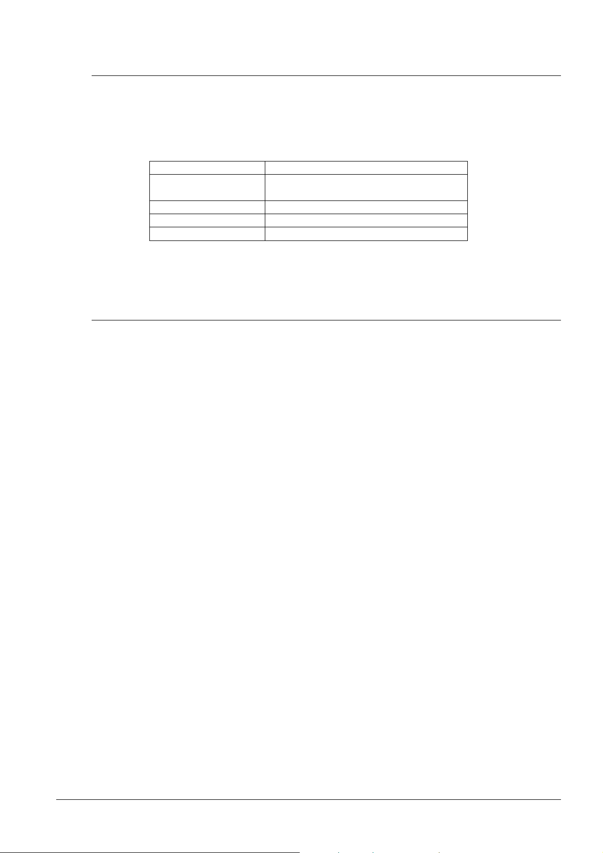
Enter data in following order depending on the item S2 setting (counting unit):
Counting unit Data order
1/100 second <Minutes>:<Seconds>.< Hundredths
of second >
1 second <Hours>:<Minutes>:<Seconds>.
1 minute <Hours>:<Minutes>
1 day <Days>
By pushing the OK button, the entered values are stored and the clock returns to the
“Stopwatch” display mode. By pushing ESC, the clock returns without storing.
7.3 Switching contact
When counting down mode is applied, the switching contact can be used (only for
certain types of clocks), which switches at zero-crossing. It is possible to control an
external device such as sound devices. There is normally open contact (NO), normally
closed contact (NC) and common contact (COM) on the relay port (JP21) available.
© MOBATIME 34 / 56 800444.05
Page 35
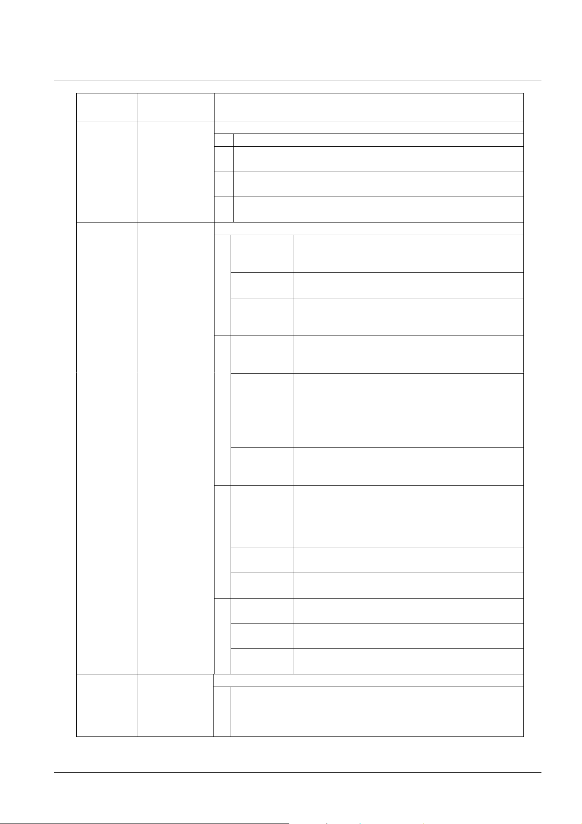
8 Stopwatch menu table
Program
Functio
n
Scope of the values
1
1
1
option
S0 Counting
direction
S1 Control of
intermediate
time periods
(correspondin
g keyboard
keys are
listed in
brackets)
S2
(default values are printed in bold)
- 4
1 upwards
downwards from a time value set in advance, with stop at
2
zero
downwards from a time value set in advance until zero,
3
with automatic restart from the specified time value
downwards from a set time value, until zero, and keeping
4
the counting into minus value
– 4
S/S
(PB3S)
HOLD
1
(PB1S)
RES
(PB1L)
S/S
(PB3S)
HOLD
2
(PB1S)
RES
(PB1L)
S/S
(PB3S)
3
HOLD
(PB1S)
RES
(PB1L)
S/S
(PB3S)
HOLD
4
(PB1S)
RES
(PB1L)
1 Counting in increments of 1/100 sec. (with 4-digit display
the counting goes on until 59.99 sec., and then continues
with displaying of minutes : seconds), up to 59 minutes and
59.99 seconds, at maximum.
Alternating START - STOP -„UNFREEZE“ of
DISPLAY
(if it was frozen)
“Freezing” of displaying data with the counter
proceeding in the counting
Setting the counter to zero in STOP operation
mode, for counting up, and return to a present
value in all other counting mode
Alternating START - STOP -„UNFREEZE“ of
DISPLAY
(if it was frozen)
The first depression of this button causes the
display to freeze on the respective time
achieved and lets the counter running.
Further activation of the button shows the
intermediate time elapsed from the first
depression of the button.
Reset of the counter in the STOP mode while
in counting up. Return to a preset value in
other counting modes.
count up from zero, or from a present value in
countdown mode. Next activation of the
button causes the display to freeze and to
resume the count from zero in counting up, or
from a preset value in countdown mode.
Unfreezing of the display, leaving the counter
to continue in counting
Counter reset (to zero), or return to a preset
time followed with counter stop
Triggering the counter
Stopping the counter
Resetting the counter or return to a preset
time, with counter stop
- 4
© MOBATIME 35 / 56 800444.05
Page 36

Counting unit
S3 Contact
closing
2 Counting in increments of 1 second (with 4-digit display the
counting goes on until 59 minutes and 59 seconds; and
follows with displaying of hours: minutes) until 23 hours, 59
minutes and 59 seconds, at maximum.
3 Counting in 1 minute steps, until 23 hours 59 minutes
4 Counting in periods after one day. A subtraction or an
addition always takes place around midnight. Capacity of
counting up to 9999 days.
When counting is stopped, the dot is displayed after the
last digit.
1 – 30,0(function disabled)
Time period of contact closing for stopwatches passing
through zero, while operating in countdown mode, starting
from a preset time moment.
© MOBATIME 36 / 56 800444.05
Page 37
9 Local time calculation
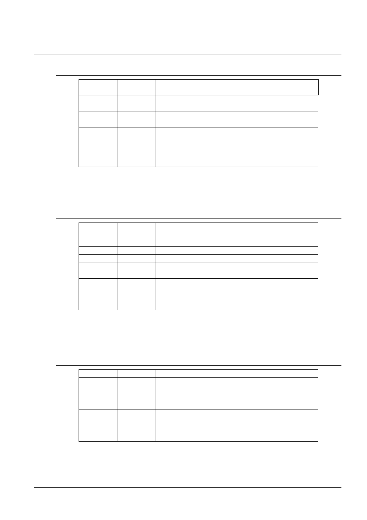
9.1 Basic setting – control according to source of synchronization
P3 A Time zone is taken over according to the source of
P4 2 – 10,
A
P6 0 Neither MOBALine time zone nor time zone server
P7 A Display time and date according to source of
R10 –R14 N The displaying of time-zone is not used; it is not
This setting is suitable for calendar clocks synchronized by a DCF receiver or
controlled by a master clock as slave clock in a time distribution system. The internal
time zone table isn’t used. The displaying time-zone isn’t needed.
9.2 Calculation using MOBALine time zones and time zone display
P3 A Time zone is taken over according to the source of
P4 4 MOBALine
P6 1 - 20 Selection of the MOBALine time zone
P7 A Display time and date according to chosen
R10 –R14 1 – 64,
N
synchronization
Synchronization signal type
are used
synchronization incl. daylight saving time
recommended to display the time-zones, as the
clock has not correct information about UTC
synchronization. The UTC time calculation is based
on the MOBALine information.
MOBALine time zone, incl. daylight saving time
selected time-zones are cyclically displayed or the
display is not used; the corresponding zone times
are calculated from UTC and preprogrammed time
zone definition
This setting is suitable for calendar digital clocks controlled by a master clock as a
MOBALine slave clock in a time distribution system with possibility to display different
MOBALine time zones.
9.3 Calculation using time zone server MOBATIME and time zone display
P3 A NTP protocol uses UTC time zone
P4 A automatic
P6 1 - 15 Selection of the time zone server time zone
P7 A Display time and date according to chosen time
zone server time zone, incl. daylight saving time
R10 –R14 1 – 64,
S1 – S15,
N
This setting is suitable for NTP and PoE calendar digital clocks controlled by
MOBATIME NTP servers which support the time zone server functionality.
© MOBATIME 37 / 56 800444.05
selected time-zones are cyclically displayed or the
display is not used; the corresponding zone times
are calculated from UTC and preprogrammed time
zone definition
Page 38
9.4 Calculation using time zone entries preconfigured by MOBA-NMS
software and time zone display
P3 A NTP protocol uses UTC time zone
P4 A automatic
P6 0 No time zone server is used
P7 U1-U7 Display time and date according to chosen
preconfigured time zone entry, incl. daylight saving
time
R10 –R14 1 – 64,
U1 – U7,
N
This setting is suitable for NTP and PoE calendar digital clocks, where several user
defined time zone entries should be used. The time zone entries are preconfigured by
means of the MOBA-NMS software.
selected time-zones are cyclically displayed or the
display is not used; the corresponding zone times
are calculated from UTC and preprogrammed time
zone definition
9.5 Calculation according to internal time zone table and time zone display
P3 0 – 64 According to the time zone in which source of
synchronization works (e.g. value 2 for DCF in west
Europe)
P4 1 – 10, A Autonomous operation or any type of the
synchronizing signal
P6 0 Neither MOBALine time zone nor time zone server
are used
P7 0 – 64, U Display time and date by calculation from the UTC
time according to chosen time zone, incl. daylight
saving time
R10 –R14 1 – 64,
N
selected time-zones are cyclically displayed or the
display is not used; the corresponding zone times
are calculated from UTC and preprogrammed time
zone definition
This setting is suitable for autonomous calendar digital clocks or in cases where the
displayed time is needed in another time zone than provided by the synchronization
source. Displayed time and date calculation is based on the internal time zone table or
on the user–specific time zone parameters. See the chapter 15 with actual time zone
definition table.
© MOBATIME 38 / 56 800444.05
Page 39

10 Non-network clock operation
Configure the jumper JP11 according to table (chapter 2.8) if the source of synchronization is
a DCF signal, Mobatime serial code, polarized impulse line, MOBALine or IRIG-B. Choose the
item P4 in main MENU (chapter 5) and set the type of synchronization. The auto detection
mode (P4:A), when the type of synchronization signal is set automatically, is applicable for
DCF signal, Mobatime serial code, MOBALine, IRIG-B, WTD. The permanently lit colon during
the time display signalizes the clock is synchronized by the synchronization source.
10.1 Autonomous clock synchronized by DCF 77 receiver
Set value A in items P3, P4 and P7 in the main MENU (chapter 5).
Connect the DCF 77 receiver to the clock terminal board placed on the anchoring
plate (LINE IN terminals) using a twin-wire cable.
The maximum wire length depends on its diameter (approx. 100 - 300 m).
In case the connection is correct and the input signal is at high level, the LED on the
receiver is flashing periodically once a second, with 1 pulse left out at the 59th
second.
If the polarity is incorrect, the LED does not flash. In such a case, interchange the
two wires.
Install the receiver at a place with a high-level radio signal. Don’t install the receiver
near sources of interfering signals, such as the personal computers, TV sets or
other types of power consumers (the calendar digital clock itself generates
interfering signals too).
Position the receiver with its transparent cover (DCF 450) or the arrow on the cover
(DCF 4500) facing the transmitter (located in Frankfurt, Germany). Presuming the
good quality DCF 77 signal the synchronization takes place in approx. 3 to 4
minutes. In case of poor quality of the signal (mainly during the day time) the first
time setting is to be done manually. The red LED of the receiver displays a working
connection by flashing once a second without flickering.
10.2 Autonomous clock synchronized by GPS receiver
Set value A in items P3, P4 and the desired time-zone in the P7 item in the main
MENU (chapter 5).
Using jumper JP17 set the power supply output (DC OUT) on pins 3, 4 of the JP1
connector.
Connect GPS receiver to the clock terminal board placed on the anchoring plate
(LINE IN and DC OUT/DCF OUT terminals) using a four-wire cable. Please note the
correct polarity of the wires – see the GPS user manual.
For the correct placing of the receiver please follow the GPS user manual.
Presuming the good position of the GPS receiver the synchronization takes place in
approx. 10 to 20 minutes.
10.3 Slave clock controlled by synchronizing impulses
On calendar digital clock connected in time distribution system controlled by
synchronizing impulses choose the item P4 in the main menu and set it according type
impulse lines (one minute, half minute, second pulses) and in item P5 choose mode of
processing impulse line (polarized / unpolarized impulses, synchronization and time
setting / synchronization only). Set the value A in items P3 and P7.
© MOBATIME 39 / 56 800444.05
Page 40

10.3.1 Synchronization and time setting – P5 mode 1 and 3
Clocks are set according to the slave line time on the Master clock.
Stop the slave line on Master clock.
Set all slave clocks on the same time. Set the current date on the calendar digital
clock. The clocks stand still and the colon flashes in 2 second interval.
Set the time of the slave line to the same time as on slave clocks.
Run the slave line on Master clock.
After receiving each impulse is displayed time increased by one minute (or by 30
seconds or 1 second respectively)
After the expiration of run-out time the slave clocks are synchronized by the time
information generated by the master clock, the colon flashes constantly.
In case of the line fault the clock displays the right time information based on its own
quartz time base. When the normal operation of the line resumes, the slave clock
adjusts itself to the time equal to the master clock.
10.3.2 Synchronization only – P5 mode 2 and 4
The clock time-base is synchronized by incoming pulses in normal operation of the
slave line.
Set current date and time on the slave clocks according the master clock time with
accuracy of ±30 seconds (or ±15 seconds, or ±0.5 second respectively).
The colon flashes in 2 second interval.
After 2-3 minutes are the clocks synchronized with the master clock. The colon is
permanently lit during the time display.
In case of the line fault the clock displays the right time information based on its own
quartz time base. When the normal operation of the line resumes, the clock
synchronizes with the incoming pulses.
10.4 Slave clock controlled by MOBATIME serial code, MOBALine, or IRIG-B
After the connection of the calendar digital clock to the signal source, time and date
are adjusted automatically, following the receipt of valid time information.
The time setting with using the serial coded line takes place within at least 3 to 4
minutes, for MOBALine and IRIG-B within 6 to 15 seconds.
10.5 Slave clock controlled by IF482 over RS232 or RS485
After the connection of the calendar digital clock to the line, time and date are
adjusted automatically, following the receipt of valid time information.
Setting the tune takes place within at least 5 minutes.
© MOBATIME 40 / 56 800444.05
Page 41

10.6 Slave clock controlled by supervised RS485
Supervised RS485 line available on the DTS.480x timeservers offers exact time
synchronization as well as monitoring the correct function of connected slave clocks.
If the DK clock should be monitored set in menu item P8 unique address in the
range 1 to 32. The value "L" means that the clocks are synchronized only (without
monitoring).
It is necessary to register the clock under the used address in DTS.
The time synchronization starts within a few tens of seconds after start-up.
Failure of slave clock function is signalized by an alarm in DTS.
On the RS485 you can use the jumper TRE - JP10 to connect the termination
resistor 120R between the signals A and B for the correct termination of RS485.
10.7 Cascaded connection of the DCF/GPS synchronized clock
Connect the DCF 77 receiver to the clock terminal board placed on the anchoring
plate (LINE IN terminals) using a twin-wire cable.
Set the passive DCF OUT output 3, 4 of the JP1 connector using the jumper JP17.
When using the GPS receiver, the external power supply is needed - parameters
12-24 VDC – min. 5VA.
Interconnect the cascaded clock using a twin-wire cable from the DC OUT / DCF
OUT terminals to the LINE IN terminals of the next clock.
In case the connection is correct and the input signal is at a high level, the LED on
the receiver and the green LED in the clock is flashing periodically once a second,
with 1 pulse left out at the 59th second.
10.8 Synchronization in WTD system
The items P3, P4 and P7 are set to value A by the production.
Set the P8 item to the address of the WTD-T transmitter.
The colon is permanently lit after successful signal receiving from WTD-T
transmitter.
10.9 Connecting the slave displays through RS485
The clock equipped with the SI interface allows connecting up to 32 slave displays,
which show the same information as the main display. The RS485 (JP5) interface is
used for the connection. Two signals (A, B) and the ground connection GND (from the
JP4) are used. For the signals A and B it is recommended to use the twisted pair (pay
attention for the same polarity by all displays), another twisted pair is used for the GND
connection.
If the overall length of the RS485 bus is longer than ca. 500m, enabling the TRE –
JP10 is recommended in the last clock.
In the clock serving as the master display, set the P13 to value 3 (DK master)
In the slave displays set the P13 to value 4 (DK slave)
Items P14 to P17 are set automatically to 9600 baud, 8 bits, even parity, 1 stop-bit.
In case of communication problems it is possible to lower the communication speed.
The modification of the items P14 to P17 is necessary to proceed in all connected
displays identically.
© MOBATIME 41 / 56 800444.05
Page 42

11 NTP and PoE clock operation
11.1 Unicast mode
The clock is synchronized to UTC (Universal Time Coordinated) from a NTP server (up
to four NTP server IP addresses configurable) and must have assigned its own IP
address. The clock requests in defined intervals the actual time from the NTP server. If
the server is not available, the clock tries to contact the other defined servers in cyclic
way until the valid response from the NTP server is received.
This operating mode supports the monitoring and configuration of the movement via
the network connection by means of the Telnet, SNMP or the MOBA-NMS software
tool. For supervision and configuration with MOBA-NMS the clock’s IP address can be
used or the multicast group address having last octet cleared to zero (presuming the
multicast is not disabled).
It is necessary to set appropriate time-zone for correct displaying of local time and date
– see chapter 9 for details.
Default network parameters:
IP address 0.0.0.0
subnet mask 0.0.0.0
default gateway 0.0.0.0
NTP server address 1 0.0.0.0
NTP server address 2 0.0.0.0
NTP server address 3 0.0.0.0
NTP server address 4 0.0.0.0
NTP request time [s] 10
DNS server 0.0.0.0
SNMP manager 1 0.0.0.0
SNMP manager 2 0.0.0.0
multicast config address 239.192.54.0
alive notification interval [min] 30
configuration port number 65532
time zone client port number 65534
DHCP enabled
SNMP enabled
Multicast support enabled
Telnet enabled
11.1.1 Network parameters assignation by DHCP
The menu item P19 must be set to value 3 (default). Network parameters are
automatically obtained from a DHCP server.
The following DHCP options will be evaluated automatically:
[50] IP address
[3] Gateway address
[1] Subnet mask
[42] List with up to four NTP server addresses
[42] Time zone server address (usually same as NTP server address)
[234] SNMP manager address
[43] or [224] Additional options (refer to document BE-800793)
The network administrator must configure the DHCP options accordingly.
Assigned parameters can be checked in the submenu of items P20 to P22.
© MOBATIME 42 / 56 800444.05
Page 43

11.1.2 Manual setting through setup menu
The menu item P19 must be set to value 2.
See chapter 4.2.4 for setting the clock’s IP address in the item P20 submenu
See chapter 4.2.5 for setting the subnet mask in the item P21 submenu
See chapter 4.2.6 for setting the gateway in the item P22 submenu
See chapter 4.2.7 for setting the multicast group address in the item P23 submenu
See chapter 4.2.8 for setting the unicast NTP server address in the item P24
submenu.
11.1.3 Manual setting through telnet
The menu item P19 must be set to value 1 or 2. To establish the first connection
through telnet, the following procedure is needed because the initial IP address of the
clock is 0.0.0.0:
assign a new IP address to the clock’s MAC address (marked on the product label)
by windows command arp -s <IP address> <MAC address>
example: arp -s 192.168.0.190 00-16-91-FE-90-00
reset the clock or power-cycle it and do the following within 2 minutes
the IP address is temporarily matched to the clock (only valid when the current IP
address is 0.0.0.0) by windows command ping <IP address> , the clock should
answer the two last ECHO requests at least
example: ping 192.168.0.190
do the following within 30 seconds after the ping
connect to the clock and make the needed settings (see lower) by windows
command telnet <IP address> or use the Hyperterminal application
Setting parameters over telnet:
request for entering the password appears after connection (default password is
718084)
the information about software and hardware version followed by the MAC address
is displayed after entering the correct password
inserted commands must be confirmed by pushing the Enter key, use the
Backspace key for correcting typing errors
command help or ? displays help with a command list
command reset resets the clock (changes are written to Flash)
command conf -p displays current parameters from setup menu
command conf –n displays current network parameters
command conf -? displays help for command conf parameters
example: conf -i 192.168.0.190 sets the clock’s IP address to 192.168.0.190
it is necessary to end telnet connection by command exit
Windows 7 note: The telnet is not activated in Windows 7 by default. For activating it go
to the “Control Panel” in “Start menu”, click on “Uninstall a program (link)” in “Control
Panel”, click on “Turn Windows features on or off (link)” in “Programs and Features”,
click in “Windows Features” box and find the “Telnet Client” check box. Allow the
system to install the appropriate files – should take only a few seconds. The
administrator rights are necessary for this operation.
.
Hyperterminal note: The Hyperterminal application can be used as an alternative to
telnet. It is necessary to activate the options “Send line ends with line feeds” and “Echo
typed characters locally” in the Properties -> Settings -> ASCII setup window.
© MOBATIME 43 / 56 800444.05
Page 44
11.1.4 SNMP
The DK clock supports SNMP version 2c notifications and parameter reading and
setting by means of SNMP GET and SET commands. This allows for integrating the
clock into a network management system. The DK clock (SNMP agent) can send alarm
and alive notifications to a SNMP manager. The IP address of the SNMP manager can
be provided to the clock by DHCP, Telnet, SNMP or the MOBA-NMS. The structure of
supported parameters is defined in a MIB file (refer to document BE-800793 for
details). In addition the clock supports the “system” node parameters defined by MIB-2
(RFC-1213)
Alarm notifications are asynchronous messages and are used to inform the manager
about the appearance / disappearance of alarms.
Alive notifications are sent out periodically to report availability and state of the clock.
The interval time can be configured.
SNMP community strings:
read community romobatime
read / write community rwmobatime
notification (trap) community trapmobatime
11.2 Multicast mode
The clock is synchronized to UTC (Universal Time Coordinated) from a NTP server.
The clock receives NTP multicast packets transmitted by the NTP server in a specified
time cycle. This type of synchronization requires no clock’s own IP address and is
therefore suitable for an easy commissioning of the large systems of slave clocks.
Further this mode supports monitoring and parameter configuration by means of
MOBA-NMS software.
For supervision and configuration with MOBA-NMS the multicast group address can be
used or the multicast group address having last octet cleared to zero.
The Multicast operating mode signifies only a minimum amount of configuration work
for a network administrator.
It is necessary to set appropriate time-zone for correct displaying of local time and date
– see chapter 9 for details.
Default network parameters:
multicast group address 239.192.54.1
multicast config address 239.192.54.0
configuration port number 65532
time zone client port number 65534
The menu item P19 must be set to value 1. See chapter 4.2.7 for setting the multicast
group address in the item P23 submenu.
© MOBATIME 44 / 56 800444.05
Page 45

12 WiFi clock operation
In the item P19, choose if the clock will be connected to default wireless network MOBA-WIFI,
where network parameters (IP address, subnet mask and gateway) will be set automatically
(DHCP), or to wireless network set by user via telnet, where network parameters could be set
manually (telnet, clock menu) or automatically (DHCP). If the DHCP is used, the parameters
assigned by the server can be checked in the items P20 to P22 submenus.
12.1 Parameters of default wireless network
Net name (SSID): MOBA-WIFI
Used coding: WPA
Coding key: hgfedcba
DHCP: allowed
12.2 Setting process
set WiFi router to parameters of default wireless network
in the item P20 submenus display assign IP address
by windows command telnet <IP address> connect to the clock and make needed
setting (see lower)
example: telnet 192.168.0.190
Setting the network parameters using telnet
it is necessary to push ENTER key after connection
the request for the password appears (initial password is 718084)
the software and hardware version displays if password entering was successful
inserted commands can be sent off using Enter key, the Backspace key serves for
correction of the typing errors
command help or ? displays help with command’s list
command reset resets the clock (setting modifications are written to data flash)
command conf –p displays the current setting of the menu parameters
command conf –n displays the current network parameters, MAC address and
wireless network parameters
command conf –? displays help for the command conf parameters
it is necessary to end telnet by command exit
After expiration of two minutes timeout after telnet ending there is another two
minute period, when the telnet is not functional. The clock is then performing the
NTP time synchronization. This period also takes place at the beginning of every
hour.
© MOBATIME 45 / 56 800444.05
Page 46

Example of setting network parameters using telnet:
command conf –l mobatime set network name of new wireless network
command conf –w 4 set version of used coding on WPA2 for new wireless network
command conf –d abcdefg set the security key for new wireless network
command conf –u 192.168.0.130 set IP address of NTP server on
192.168.0.130
command conf –p19:02 set the clock for connecting to the new initiated wireless
network with manually preset network parameters
command conf –i 192.168.0.190 set clock IP address to 192.168.0.190
command conf –s 255.255.255.0 set subnet mask of the clock on 255.255.255.0
command conf –g 192.168.0.254 set gateway of the clock on 192.168.0.254
command exit ends telnet and writes changes into Flash
© MOBATIME 46 / 56 800444.05
Page 47

13 Testing mode, parameter reset
13.1 Synchronization test
The synchronization signal receive process can be displayed in special testing mode.
This can be useful for example when the problems with the DCF signal receipt appear.
Display description during synchronization test mode:
Two digits on the left side show the current DCF bit number (goes up from 0 to 58).
Third digit shows the type of current DCF bit (0 or 1). The last digit shows the number
of successfully received DCF telegrams. The colon indicates that the DCF bit is
currently received. The dot behind the last digit signalizes synchronized clock.
Entering the synchronization test mode:
Enter the clock menu, move to the software version item by several pushes of the
PB1S.
Keep pushing both buttons on the clock frame simultaneously until the display
shows C0:00
Use the PB2 or + button on IR to set the value behind the colon to 03
Keep pushing simultaneously both clock buttons or the DISP button on IR, until the
display shows synchronization information
13.2 Parameter reset
If necessary, the clock parameters can be set to factory defaults by the following
procedure.
Activating the parameter reset:
Enter the clock menu, move to the software version item by several pushes of the
PB1S.
Keep pushing both buttons on the clock frame simultaneously until the display
shows C0:00
Using the PB2 or + button on IR set the value behind the colon to 04
Keep pushing simultaneously both buttons or the DISP button on IR, until the
display shows FAC1 and clock makes reset
© MOBATIME 47 / 56 800444.05
Page 48

14 Firmware update
14.1 Firmware update using RS232
Switch-off the clock.
Install and run the Flash Magic software.
Open the configuration file „LPC2366 dc3.fms“ over the File -> Open Settings menu
Set used COM Port and open file firmware „DK_<version>.hex“ (e.g.
DK_NTP_POE_v349.hex) using the Browse key
Connect the programmer to serial COM Port of computer (the USB-RS232 converter
can be used) and connect the power supply to the jack on the programmer.
Install the jumper ISPE (JP9).
Connect the programmer to connector PROG (JP8). The POWER LED placed on
the clock lights up.
Click the Start button to run programming; after completion, a “Finished” message
will be displayed in the bottom part of the widow
Disconnect the programmer and remove the ISPE jumper.
Firmware version can be checked in the last item of the clock menu.
14.2 Firmware update over Ethernet on NTP and PoE versions
Create a folder on the computer disk and copy "tftpd32.ini", "tftpd32.chm" and
"tftpd32.exe" in it. Copy the new firmware file "devapp.bin" as well.
Run "tftpd32.exe", let only the TFTP Server in the window Settings -> Global
Settings be active, don’t change other settings.
Using the Browse key, open choice of active directory and find the one which
contains the given firmware
Connect to the clock by the windows command telnet <clock IP address>
example: telnet 192.168.0.190
The page of telnet requesting will appear, after the password entered identification
of current software version and clock MAC address displays.
Enter the command fu in telnet window to start the automatic clock firmware update
from the "devapp.bin" file.
Information about sending file and its progress displays in the tftpd32 program
window after the command entering. Connection to telnet is ended automatically.
Wait about 1 minute after downloading the file. Connect the telnet to the clock again.
After entering the password, check if the firmware version is correct, if it isn’t, it is
necessary to repeat the whole procedure.
Close the telnet window and end the program tftpd32 with the command exit.
© MOBATIME 48 / 56 800444.05
Page 49
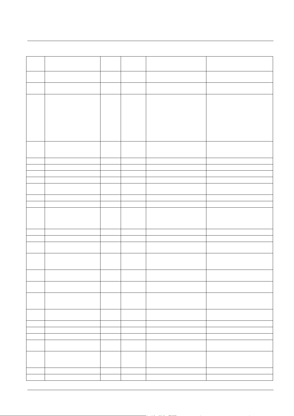
15 Time zone table
Time zone entries in the standard time zone table (version 10.0).
Time
zone
00 UTC (GMT),
01 London, Dublin,
02 Brussels, Amsterdam,
03 Athens, Istanbul, Helsinki,
04 Bucharest, Romania +2 Yes Last Sun. Mar. (03:00) Last Sun. Oct. (04:00)
05 Cairo, Pretoria, Harare +2 No
06 Amman +2 Yes Last Thu. Mar. (23:59) Last Fri. Oct. (01:00)
07 UTC (GMT) 0 No
08 Kuwait City, Minsk,
09 Praia, Cape Verde -1 No
10 UTC (GMT) 0 No
11 Abu Dhabi, Muscat,
12 Kabul +4.5 No
13 Adamstown (Pitcairn Is.) -8 No
14 Tashkent, Islamabad,
15 Mumbai, Calcutta,
16 Astana, Thimphu, Dhaka,
17 Bangkok, Hanoi, Jakarta,
18 Beijing, Chongqing, Hong
19 Tokyo, Osaka, Sapporo,
20 Gambier Island -9 No
21 South Australia: Adelaide +9.5 Yes 1stSun. Oct (02:00) 1stSun. Apr. (03:00)
22 Northern Territory: Darwin +9.5 No
23 Brisbane, Guam, Port
24 Sydney, Canberra,
25 UTC (GMT) 0 No
26 UTC (GMT) 0 No
City / State UTC
Monrovia, Casablanca
Edinburgh, Lisbon
Berlin, Bern,
Copenhagen, Madrid,
Oslo, Paris, Rome,
Stockholm, Vienna,
Belgrade, Bratislava,
Budapest, Ljubljana,
Prague, Sarajevo,
Warsaw, Zagreb
Riga, Tallinn, Sofia,
Vilnius
Kaliningrad
Tbilisi, Moscow, St.
Petersburg, Volgograd,
Samara
Karachi
Madras,
New Delhi, Colombo
Yekaterinburg
Novosibirsk
Kong, Singapore, Taipei,
Urumqi, Krasnoyarsk
Seoul, Irkutsk
Moresby, Yakutsk
Melbourne, Tasmania:
Hobart
DST
Offset
+5.5 No
+10 No
+10 Yes 1stSun. Oct. (02.00) 1stSun. Apr. (03:00)
Change
0 No
0 Yes Last Sun. Mar. (01:00) Last Sun. Oct. (02:00)
+1 Yes Last Sun. Mar. (02:00) Last Sun. Oct. (03:00)
+2 Yes Last Sun. Mar. (03:00) Last Sun. Oct. (04:00)
+3 No
+4 No
+5 No
+6 No
+7 No
+8 No
+9 No
Standard → DST DST → Standard
© MOBATIME 49 / 56 800444.05
Page 50
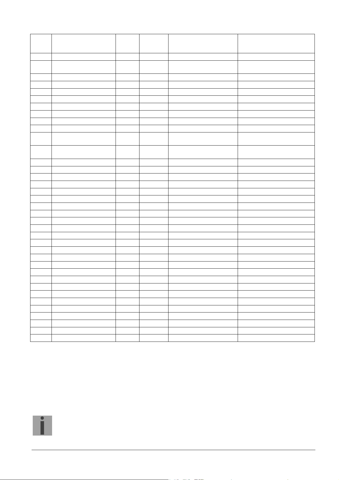
27 Honiara (Solomon Is.),
+11 No
Noumea (New
Caledonia), Vladivostok
28 Auckland, Wellington +12 Yes Last Sun. Sep. (02:00) 1stSun. Apr. (03:00)
29 Majuro (Marshall Is.),
+12 No
Magadan, Anadyr
30 Azores -1 Yes Last Sun. Mar. (00:00) Last Sun. Oct. (01:00)
31 Middle Atlantic -2 No
32 Brasilia -3 Yes 3rdSun. Oct. (00:00) 3rdSun. Feb. (00:00)
33 Buenos Aires -3 No
34 Newfoundland, Labrador -3.5 Yes 2ndSun. Mar. (02:00) 1stSun. Nov. (02:00)
35 Atlantic Time (Canada) -4 Yes 2ndSun. Mar. (02:00) 1stSun. Nov. (02:00)
36 La Paz -4 No
37 Bogota, Lima, Quito -5 No
38 New York, Eastern Time
-5 Yes 2ndSun. Mar. (02:00) 1stSun. Nov. (02:00)
(US & Canada)
39 Chicago, Central Time
-6 Yes 2ndSun. Mar. (02:00) 1stSun. Nov. (02:00)
(US & Canada)
40 Tegucigalpa, Honduras -6 No
41 Phoenix, Arizona -7 No
42 Denver, Mountain Time -7 Yes 2ndSun. Mar. (02:00) 1stSun. Nov. (02:00)
43 Los Angeles, Pacific Time -8 Yes 2ndSun. Mar. (02:00) 1stSun. Nov. (02:00)
44 Anchorage, Alaska (US) -9 Yes 2ndSun. Mar. (02:00) 1stSun. Nov. (02:00)
45 Honolulu, Hawaii (US) -10 No
46 Midway Islands (US) -11 No
47 Mexico City, Mexico -6 Yes 1stSun. Apr. (02:00) Last Sun. Oct. (02:00)
48 Adak (Aleutian Is.) -10 Yes 2ndSun. Mar. (02:00) 1stSun. Nov. (02:00)
49 UTC (GMT) 0 No
50 UTC (GMT) 0 No
51 UTC (GMT) 0 No
52 UTC (GMT) 0 No
53 UTC (GMT) 0 No
54 Scoresbysund, Greenland -1 Yes Last Sun. Mar. (00:00) Last Sun. Oct. (01:00)
55 Nuuk, Greenland -3 Yes Last Sat. Mar. (22:00) Last Sat. Oct. (23:00)
56 Qaanaaq, Greenland -4 Yes 2ndSun. Mar. (02:00) 1stSun. Nov. (02:00)
57 Western Australia: Perth +8 No
58 Caracas -4.5 No
59 CET standard time +1 No
60 Santiago, Chile -4 Yes 2ndSun. Oct. (00:00) 2ndSun. Mar. (00:00)
61 Chile, Easter Island -6 Yes 2ndSat. Oct. (22:00) 2ndSat. Mar. (22:00)
62 Baku +4 Yes Last Sun. Mar. (04:00) Last Sun. Oct. (05:00)
63 UTC (GMT) 0 No
64 UTC (GMT) 0 No
In countries where the DST switch date changes annually (e.g. Iran, Israel), the time zone has to be defined manually in the user time zone
table (entries 80 – 99).
Legend:
UTC: Universal Time Coordinate, equivalent to GMT
DST: Daylight Saving Time
DST Change: Daylight Saving Time changeover
Standard DST: Time change from Standard time (Winter time) to Summer time
DST Standard: Time change from Summer time to Standard time (Winter time)
Example:
2ndlast Sun. Mar. (02:00) Switch over on the penultimate Sunday in March at 02.00 hours local time
Attention! The Time Zone Table is usually updated every year. The current table is available for download under the
following address: www.mobatime.com Customer Area Customer Support Support Resources
Software Tools Time Zone Table. In case your device is equipped with a newer version than shown in this
manual, the current time zone settings should be checked.
© MOBATIME 50 / 56 800444.05
Page 51
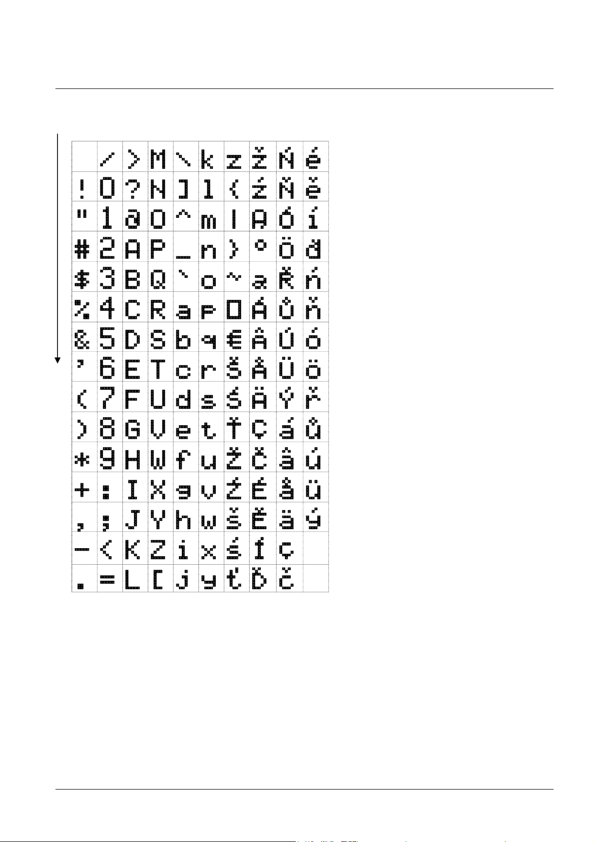
16 Character set
Code page 1250
© MOBATIME 51 / 56 800444.05
Page 52
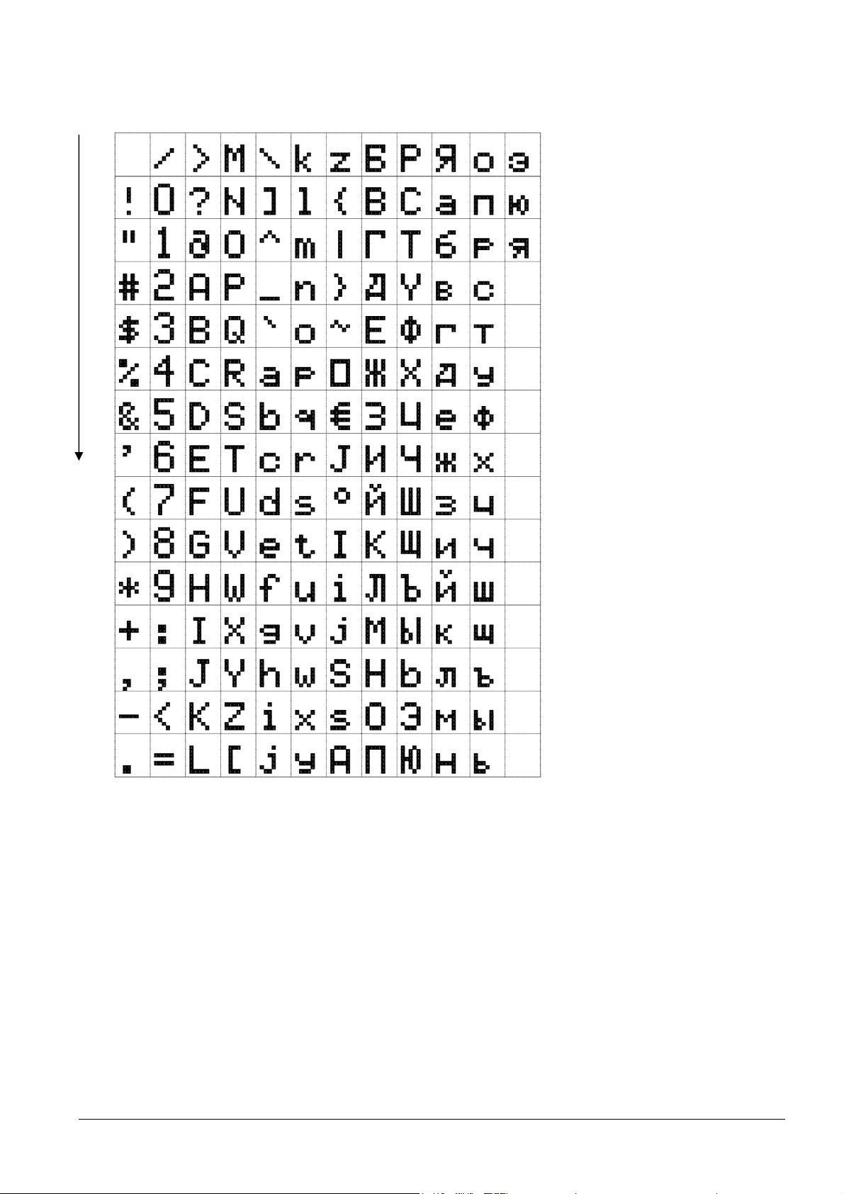
Code page 1251
© MOBATIME 52 / 56 800444.05
Page 53
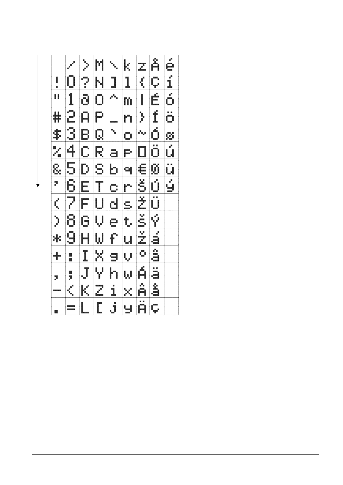
Code page 1252
© MOBATIME 53 / 56 800444.05
Page 54
17 Additional information
17.1 Accessories - single-sided clock
Allen key for unlocking and locking the frame catch 1 pc
Instruction manual 1 pc
Additional spacers 3 pcs
Wood screws for fixing the anchoring 3 pcs
plate inclusive dowels
17.2 Accessories - double side clock
Allen key for unlocking and locking the frame catch 1 pc
and the suspension
Instruction manual 1 pc
Wood screws for fixing the suspension 4 pcs
including dowels
17.3 Cleaning
Clean surface of clock only. Use soft rags and antistatic detergents. Don’t use
synthetics.
17.4 Disposal of used batteries
The user is lawfully obligated to return unusable batteries. Disposal
of used batteries through household waste is prohibited! Batteries
which contain dangerous substances are labelled with a picture of a
crossed out trash bin. The symbol means that this product may not
be disposed through household waste. Below the symbol, the
dangerous substance is indicated with an abbreviation: Cd =
Cadmium, Hg = Quicksilver, Pb = Lead. Unusable batteries can be
returned free of charge at appropriate collection points of your
waste disposal company or at shops that sell batteries. By doing so,
you fulfill your legal responsibilities and help protect the
environment.
17.5 Guarantee and maintenance
The device is intended for a normal operational environment according to the
corresponding standard.
The following circumstances are excluded from the guarantee:
- inappropriate handling or interventions
- chemical influences
- mechanical defects
- external environmental influences (natural catastrophes)
Repairs during and after the guarantee period are assured by the manufacturer.
© MOBATIME 54 / 56 800444.05
Page 55
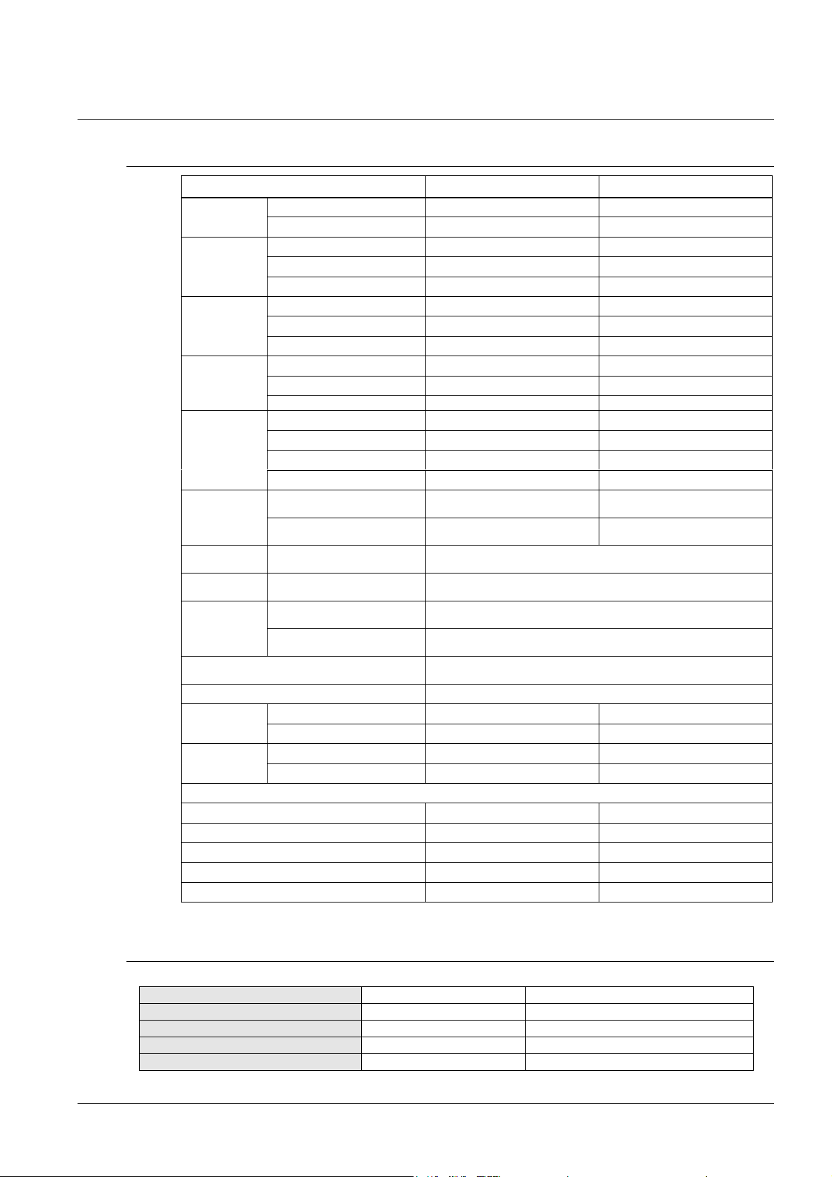
18 Technical data
Dimensions
mm
Type of slave line
Voltage range
Electric current consumption
18.1 Standard design of the clock
Specifications DK.57.4 DK.57.6
Display
Time display
format
Date display
format
Powering
Power
consumption
(red, green
and amber
color display)
Power
consumption
(blue and pure
green)
Reserve
capacity
Accuracy at
20 °C
Accuracy of
temp.
measurement
in range
Scope of the operating temp. 0 to + 50 °C, relative humidity 0 - 95%, without condensation
height of the digits 57 57 / 38
number of digits 4 4 + 2
HH:MM
HH.MM:ss
HH:MM:SS
DD.MM
DD.MM.yy
DD.MM.YY
100-240 V, 50-60 Hz
24 V= ± 20%
PoE (IEEE 802.3 af-Class 0)
single-sided 8 VA 8 VA
single-sided PoE 7 VA 7 VA
double-sided 15 VA 15 VA
double-sided PoE 14 VA 14 VA
single-sided 8 VA 11 VA
double-sided 15 VA 19 VA
passive (time + data) 6 years (except PoE version)
without synchronization ±0,3 sec/day
-25...+80 °C ±0,5 °C
-50...+125 °C ±2,0 °C
Protection degree IP 40, optionally IP 54
Weight in kg
(W x H x D)
Accessories:
DCF 4500 radio signal receiver √ √
GPS 4500 receiver √ √
Temperature sensor IP66 √ √
Keyboard for stopwatch control, cable 5 m √ √
IR remote control √ √
single-sided design 1.4 1.8
double-sided design 2.6 3
single-sided design
double-sided design 700x118x78 780x118x78
700x118x39 780x118x39
18.2 Voltage range and electric current consumption of the lines
MOBALine 5 – 30 VAC 6 – 34 uA
MIN, CODE +- 12 – 30 V 10 – 18 mA
MIN, CODE (on request) +- 30 – 60 V 10 – 18 mA
IRIG B 20 mVpp – 2 Vpp 20 uA – 2 mA
© MOBATIME 55 / 56 800444.05
Page 56

© MOBATIME BE-800444.05
 Loading...