

Page 1
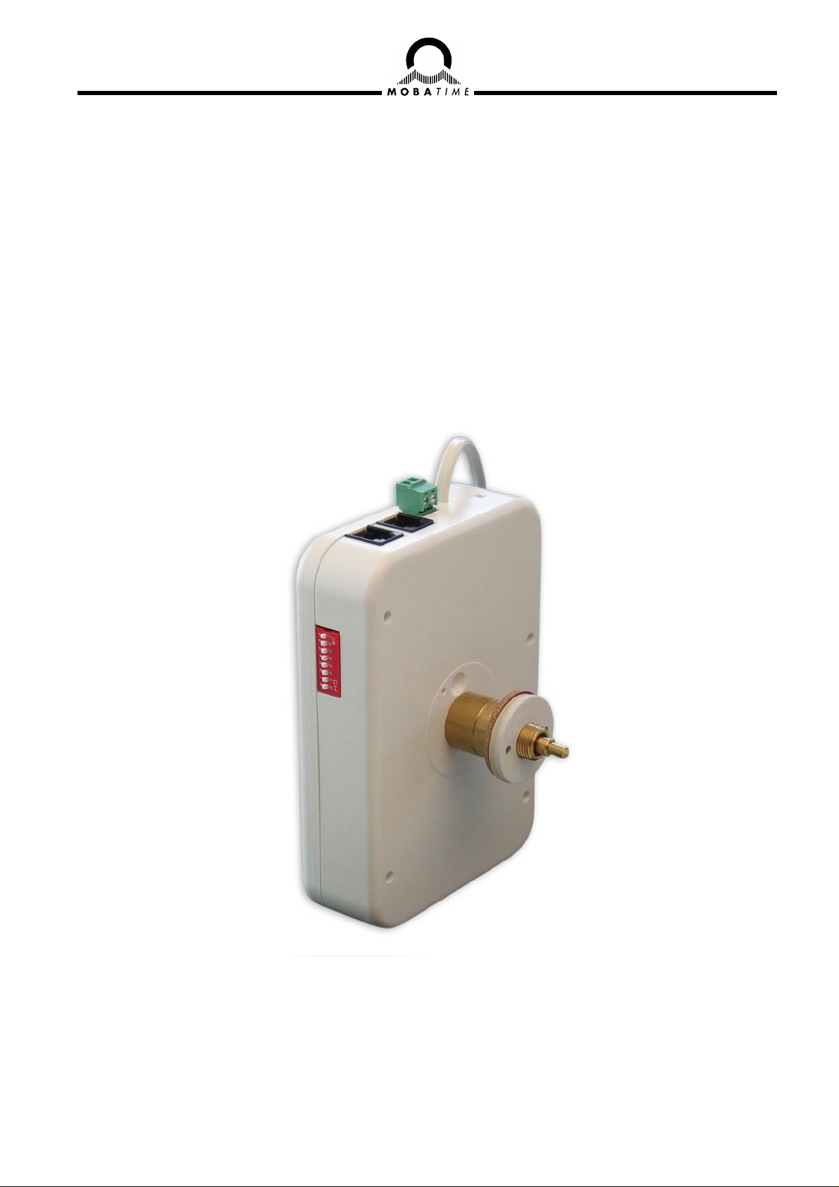
Installation and Operating
BU 190(t) 230
Movement for DCF / MSF time code
Please read this instructions carefully before installation.
© MOBATIME BE-800603.01
Page 2

References to the User’s Manual
1. The information in this User’s Manual can be changed at any time without previous notice.
The current version is available for download on www.mobatime.com – Downloads.
2. This User’s Manual has been composed with utmost care, in order to explain all details in respect of the
operation of the product. Should you, nevertheless, have questions or discover errors in this Manual,
please contact us.
3. We do not answer for direct or indirect damages, which could occur, when using this Manual.
4. Please read the instructions carefully and start the setting-up of the product, only once you have correctly understood all information for the installation and of the operation.
5. The installation must only be carried out by skilled staff.
6. It is prohibited to reproduce, to store in a computer system or to transfer this publication in a way or another, even part of it. The copyright remains with all the rights with MOSER-BAER AG, CH-3454 Sumiswald / Switzerland.
Guidelines for installation and handling
1. This movement has no incorporated disconnect device from the mains supply power. An appropriate
disconnect device must be provided external to the movement, concerning to the national installation
regulations.
2. The movement has to be transported or stocked only in the original packing and in a dry environment.
© MOBATIME 2 / 12 800603.01
Page 3

Content
1. Dimensions, Definitions..............................................................................................................4
2. Function description ...................................................................................................................5
3. Mounting guidelines....................................................................................................................5
3.1 Mounting of movement series 190(t).......................................................................................5
3.2 Mounting of hands and Starting-up.........................................................................................5
3.2.1 Mounting of hands ............................................................................................................................5
3.2.2 Starting-up and check of the hand position ......................................................................................6
4. Setting up / Connections.............................................................................................................6
4.1 Synchronization with DCF or MSF time code..........................................................................6
4.2 Synchronization with serial time telegram (IF 482)..................................................................7
4.3 Connection / cascading ..........................................................................................................7
5. Serial Telegrams..........................................................................................................................8
5.1 Standard Time Telegram (IF 482) with Local Time .................................................................8
6. Technical specification ...............................................................................................................9
© MOBATIME 3 / 12 800603.01
Page 4

1. Dimensions, Definitions
AC 230V
Diameter Type Art.-No.
30 - 80 cm Movement: BU 190 230 201404
30 - 80 cm Movement: BU 190t 230 201405
Clock dial
35 5
67.5
Ø 12.3
136.5
BU 190t 230
Fig. 1
Connection to
the mains
supply should
be realized
according to
the class II
protection.
Power
Cable length
550mm
Fig. 2
10
Hour hand
Disc nuts
Minute hand
Cover glas
BU 190 230
67.5
136.5
10
94
9.4
13.7
35
20.2
4
6
M12x1
BU 190t 230
9
32
35
36.5
42.4
4
6
M12x1
© MOBATIME 4 / 12 800603.01
Page 5
2. Function description
Self-setting movement with hour and minute display. For autonomous self-setting clocks for indoor or
outdoor use with dial diameters up to 80 cm, with or without illumination.
DCF-77 or MSF-60 radio control with automatic time take-over and daylight saving time
change-over by means of a connected radio time signal receiver.
Central-European time zones CET-1, CET and CET+1 selectable by DIP-switch.
Signalization of missing DCF/MSF time code reception after a period of one week by setting
the hands to 12 o'clock position.
Internal battery-less power reserve for at least 5 minutes operation (not for second hand).
Internal quartz clock for precise time display even without DCF/MSF radio reception.
Immediate resetting to the correct time after mains failure of up to 12 hours due to an internal
real-time-clock (battery-less powered).
Serial time signal output for the connection of a further movement. Up to 3 further movements
can be connected in this way.
Possibility of connection of an MSF-60 radio receiver (Rugby) as well.
Serial input (RS 232 / 422) for time setting and synchronization with standard ASCII time tele-
gram (definition IF482).
1
3. Mounting guidelines
3.1 Mounting of movement series 190(t)
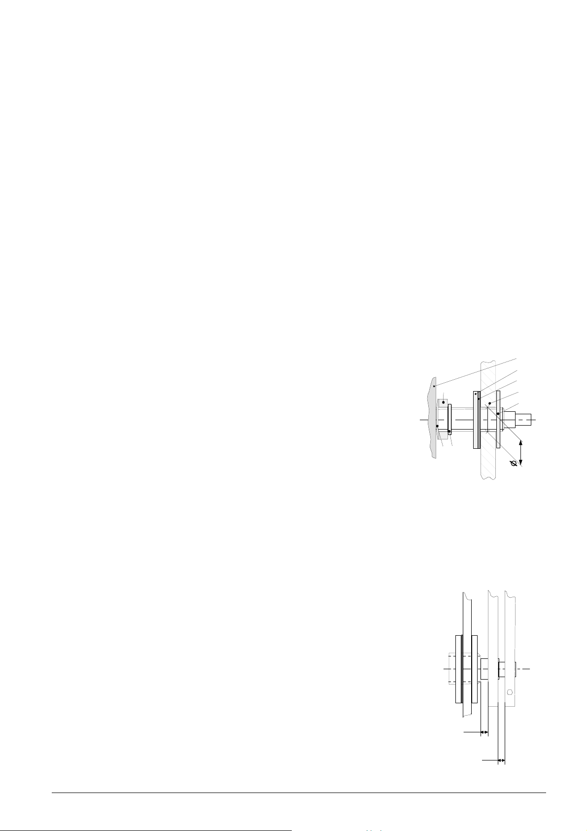
The dial must be sufficiently stable. The fixing hole must have a diameter of 12.3 mm.
The movement must be fixed in vertical position.
Vide Fig. 3 for the position of mounting parts.
The disc nut (2*) M12 x 1 has to be tightened with a special wrench tool
(Art. No. 201998) and a torque wrench with a torque of 4.5 Nm +/- 0.2
Nm.
Attention:
The ring nut (5), the compensation ring (6) and the spring washer (7)
must not be removed.
After tightening of the disc nut (2*), the movement must not be
wrenched!
190t
6
5
7
Fig. 3
1 Movement
2 Disc nut
3 Rubber washer
4 Dial
5 Ring nut
6 Compensation ring
7 Spring washer
2
3
4
2*
12.3
3.2 Mounting of hands and Starting-up
3.2.1 Mounting of hands
The shafts of the hour, minute and second hands are positioned ex-work on
the reference position (12 o’clock). The hands shall be carefully fixed and
tightened on the shafts. Enough space must be provided between the hands.
See Fig. 4.
The position 12 o’clock must be checked on each movement after the mounting (Chap.3.2.2).
x
Fig. 4
© MOBATIME 5 / 12 800603.01
x
Page 6
3.2.2 Starting-up and check of the hand position
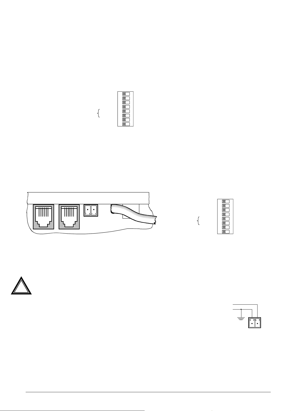
Set DIP switch 1 to ON position (12:00 Position, Fig. 5)
Install the AC 230V power supply by using the white two wire cable from the movement.
The clock runs to 12 o’clock position
Position of hands OK?
If the hand position is wrong, carefully loosen the hand, adjust and tighten.
Reset DIP Switch 1 to OFF position
Check the 12 o’clock position again (initialising by an interruption of the power supply).
If hand position OK, continue with chapter 4 for further setting up.
1 2 3 4 5 6 7 8
Hands:
Synchronization:
Time zone:
On time
reserved
reserved
DCF
CET
CET
reserved
reserved
ON
12:00 Position
reserved
reserved
MSF
CET+1
CET-1
reserved
reserved
Fig. 5
4. Setting up / Connections
If the 12 o’clock position of the clock is OK, reset DIP Switch 1 to OFF position (Fig. 5).
The movement can be synchronized with following time codes:
- DCF, MSF (see chapter 4.1)
- Serial time telegram (standard IF 482 telegram) by RS 232 or RS 422 with local time
(see chapter 4.2)
IN OUT
DCF
+ / -
AC
230V
Hands:
Synchronization:
Time zone:
On time
reserved
reserved
DCF
CET
CET
reserved
reserved
1 2 3 4 5 6 7 8
ON
12:00 Position
reserved
reserved
MSF
CET+1
CET-1
reserved
reserved
Fig. 6 Fig. 7
4.1 Synchronization with DCF or MSF time code
The DCF 77 - Radio time signal receiver (DCF / MSF 450 (4500) must be connected with plug DCF
on the movement (see fig 6).
To ensure the reception quality, the designated pin of DCF plug has to be connected with earth po-
tential (e.g. clock housing).
select time codes:
- For DCF set DIP-switch 4 to OFF position
- For MSF set DIP-switch 4 to ON position
Time: London local time (WET)
Select time zones:
Depending upon condition DCF can also be received in west Europe
(CET –1) (Greece, Portugal), or in east Europe (CET +1).
- for CET –1 set DIP-switch 6 to ON position
- for CET +1 set DIP-switch 5 to ON position
Fig. 8
DCF/MSF rec.
DCF/MSF
To ensurethe reception
quality, the designated pin
of theDCF plughas to be
connected with the earth
potential (functional earth,
i.e. clockhousing).
© MOBATIME 6 / 12 800603.01
Page 7
Control of the reception quality:
DCF-FSK
Receiver
The orientation of the radio time signal receiver should be chosen in a way, the LED of the receiver
flashes regularly (at good reception quality the LED in the receiver flashes regularly in second
rhythm), see also the instruction manual of the receiver.
The movement starts after about 5 minutes and set itself automatically on the exact time.
4.2 Synchronization with serial time telegram (IF 482)
The movement can be synchronized with RS 432 or RS 485 over standard-RS 485 telegram. Time
will be interpreted and shown as local time. See chapter 5.1 for telegram definition.
1
1 TTL IN(RxD)
2 GND
3 RS-232 IN (RxD)
4 nc
5 RS-422 IN (RD +)
6 RS-422 IN (RD -) View from contact side
2
3
4
5
6
Fig. 9
4.3 Connection / cascading
DCF Radio
IRIG-B / AFNOR
OFF ON
IF 487
LED
BU 190(t) 230
A/N:200 840. 02
BU 190t 230
230 V±10% ;5 0-60Hz; 10 mA
P/N:03959 665001
Option2
Option1
MEZ Timezone/ Zeitzone
MEZ -1
MEZ Timezone/ Zeitzone
MEZ +1
DCF Antenna/An tenne
MSF
Nones top/ ohne Stop
StopMode Secondhand/
Wobbling/S chritt Sekundenzeiger
Cont./ Kon tinuierlich
1 2 3 4 5 6 7 8
ON
normal Clockha nds/ Zeiger
12.00P osition
DCF
OUTIN
+/ -AC230V
AC
230V
BU 190(t) 230
A/N:200 840. 02
BU 190t 230
230V ±10% ;50-6 0Hz; 10 mA
P/N: 03959665 001
Option2
Option1
MEZ Timezone/ Zeitzone
MEZ -1
MEZ Timezone/ Zeitzone
MEZ +1
DCF Antenna/Antenne
MSF
Nones top /ohn eStop
StopMode Secondhand/
Wobbling/S chritt Sekundenzeiger
Cont./ Ko ntinuierlich
1 2 3 4 5 6 7 8
ON
normal Clockhands/ Zeiger
12.00 Position
DCF
OUTIN
+/ -AC230V
AC
230V
Connection to
the mains
supply should
be realized
according to
the class II
protection.
DCF
COM 192
Fig. 10
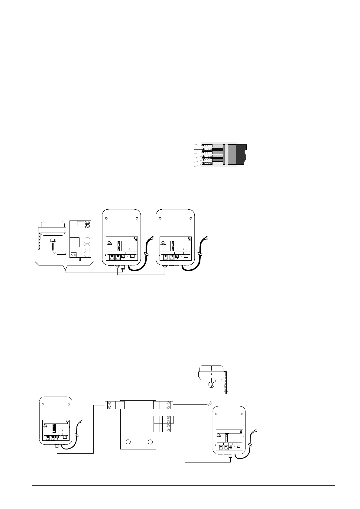
To connect the radio signal to a double sided clock (two movements), there are two possibilities:
Possibility 1: The radio signal can be distributed on both movements with a DCF multipler
(Art.No. 35 821) (Fig. 11).
Possibility 2: The time signal is sent to the second movement over a "COM 192" cable (Art. No.
200045). Therefore the signal is connected from the OUT-plug of the master-movement
to the IN-plug of the slave movement (Fig.10). Disadvantage: If master-movement fails,
slave-movement will also stop.
DCF 4500
+
master
-
BU 190(t) 230
BU190t 230 A/N:200 840.02
230V ±10%; 50-60Hz; 10 mA
P/N:03959665 001
Option2
Option1
MEZ Timezone/Zeitzone
MEZ-1
MEZ Timezone/Zeitzone
MEZ+1
DCF Antenna/Antenne
MSF
Nonestop /ohne Stop
StopMode Secondhand/
Wobbling/Schritt Sekundenzeiger
Cont./ Kontinuierlich
1 2 3 4 5 6 7 8
ON
normal Clockhands/Zeiger
12.00Position
DCF
OUTIN
+/ -AC230V
AC
230V
DCF
Multipler
Movement 1 Movement 2
-
ant.
+
35 821
-
out 1
+
out 2
-
+
BU 190(t) 230
A/N:200 840.02
BU190t 230
230V ±10%; 50-60H z;10 mA
P/N:03959665 001
Option2
Option1
MEZ Timezone/Zeitzone
MEZ-1
MEZ Timezone/Zeitzone
MEZ+1
MSF
DCF Antenna/Antenne
StopMode Secondhand/
Nonestop /ohne Stop
Wobbling/Schritt Sekundenzeiger
Cont./ Kontinuierlich
1 2 3 4 5 6 7 8
normal Clockhands/Zeiger
12.00Position
ON
DCF
OUTIN
+/ -AC230V
Fig. 11
© MOBATIME 7 / 12 800603.01
Page 8

5. Serial Telegrams
5.1 Standard Time Telegram (IF 482) with Local Time
Definition: Time telegram (ASCII), terminating at the designed second in the telegram:
9600 bit/s, 7 data bits, even parity, 1 stop bit. Jitter < 50 ms.
Format:
Byte Nr. Designation Sign HEX Code
1 Stat sign O 4F
2 Supervision 1) A or M 41 or 4D
3 Time-Season 3) W, S or L 57, 53 or 4C
4 Year tens 0 .. 9 30 .. 39
5 Year units 0 .. 9 30 .. 39
6 Month tens 0 or 1 31 or 31
7 Month units 0 .. 9 30 .. 39
8 Day tens 0 .. 3 30 .. 33
9 Day units 0 .. 9 30 .. 39
10 Monday .. Sunday 2) 1 .. 7 31 .. 37
11 Hours tens 0 .. 2 30 .. 32
12 Hours units 0 .. 9 30 .. 39
13 Minutes tens 0 .. 5 30 .. 35
14 Minutes units 0 .. 9 30 .. 39
15 Seconds tens 0 .. 5 30 .. 35
16 Seconds units 0 .. 9 30 .. 39
17 Telegram end CR 0D
1) 'A': Correct time code reception from the transmitter. 'M': No time signal has been received during
more than 12 hours (Time will be taken over at 'A' and 'M').
2) Weekday not evaluated by BU 190(t).
3) Winter, Summer or Local time: Will be checked but not evaluated.
© MOBATIME 8 / 12 800603.01
Page 9
6. Technical specification
BU 190 S 230
BU 190t S 230
www.mob
atime.com
Synchronisation DCF-77: with time signal receiver DCF 450, DCF 4500
MSF-60: with time signal receiver MSF 4500
Serial: with standard IF 482 telegram over RS-232 / 422
Setting times:
Running time to reference pos.
Read in of time
Running time for new adjustment
Changes of daylight saving time
Operation mode minute shaft 1 step every 60 s
Operation mode hour shaft continuous
Operation voltage
Power consumption < 3 VA
Stand-by reserve at least 5 min.
Time keeping with internal quartz clock > 12 h
Number of motors 1 (hour / min.)
Dial diameter 25 – 80 cm
Max. dial thickness 4 mm 14.5 mm
Temperature range -30 ... +70°C
Weight 320 g 360 g
Standards EN 50121-4, EN 61000-6-3
Savety EN 60950-1, Protection class II
serial: 3 – 5 seconds / radio signal: 3 – 5 minutes
6 minutes maximum
10 seconds – 6 minutes
5.5 minutes maximum
230 VAC 10% 50 – 60Hz
Subject to change without notice
© MOBATIME 9 / 12 800603.01
Page 10

© MOBATIME 10 / 12 800603.01
Page 11

© MOBATIME 11 / 12 800603.01
Page 12

SALES SWITZERLAND
MOBATIME AG
Stettbachstrasse 5 CH-8600 Dübendorf
Tel. +41 44 802 75 75 Fax +41 44 802 75 65
[email protected] www.mobatime.ch
SALES WORLDWIDE
MOSER-BAER SA – EXPORT DIVISION
19 chemin du Champ-des-Filles CH-1228 Plan-les-Ouates/GE
Tel. +41 22 884 96 11 Fax. +41 22 884 96 90
[email protected] www.mobatime.com
MOBATIME SA
En Budron H 20 CH-1052 Le Mont-sur-Lausanne
Tél. +41 21 654 33 50 Fax +41 21 654 33 69
[email protected] www.mobatime.ch
SALES GERMANY, AUSTRIA
BÜRK MOBATIME GmbH
Postfach 3760 D-78026 VS-Schwenningen
Steinkirchring 46 D-78056 VS-Schwenningen
Telefon +49 7720 8535 - 0 Telefax +49 7720 8535 - 11
Internet: http://www.buerk-mobatime.de E-Mail: [email protected]
© MOBATIME BE-800603.01
Spitalstrasse 7 CH-3454 Sumiswald
Tel. +41 34 432 46 46 Fax. +41 34 432 46 99
[email protected] www.mobatime.com
PRODUCTION
MOSER-BAER AG
 Loading...