

MOBASE ELECTRONICS SYECFWPC1806 User Manual
U S E R M A N U A L
Page
1/11
Established By
W.P.C SYSTEM
Spec No.
Seoyon Electronics
I N D E X
1. PURPOSE
2. SCOPE
3. ABBREVIATIONS AND DEFINITIONS
4. SYSTEM OVERVIEW
-
RELEASED
ALL
2017.05.26
W.C NO
Rev.NO
DESCRIPTION OF CHANGED
CHANGE PAGE
REV. DATE
REV. BY
REV. DATE
2017.05.26
SORT
PREPARED
CHECKED
APPROVED
A
P
P
R
O
V
A
L
WON CHUL
NO
HO NAM
KIM
GYEONG HEUM
CHOI
(PLM MANAGEMENT
SYSTEM)
DSF-4-02-01A-1 SEOYON ELECTRONICS A4(210x297)
U S E R M A N U A L
Model name :
Document Change History
Date
Ver.
Editor
Chap.
Description
CR#
SYECFWPC1806
Brand name :
HYUNDAI/KIA

U S E R M A N U A L
Model name :
SYECFWPC1806
Brand name :
HYUNDAI/KIA
Contents list page
1. PURPOSE ............................................................................................................................................... 4
2. SCOPE ................................................................................................................................................ 4
3. ABBREVIATIONS AND DEFINITIONS .......................................................................................... 4
4. SYSTEM OVERVIEW ........................................................................................................................ 6
4.1. SYSTEM DESCRIPTION ........................................................................................................................................6
4.2. OPERATION PRINCIPLE .......................................................................................................................................6
4.3. ROLE AND CHARATERISTICS OF W.P.C PING ................................................................................................8
4.4. W.P.C COMMUNICATION AND CHARGING CHARACTERISTICS ............................................................. 10
4.5. PACKET LIST OF W.P.C CONTROLLER ........................................................................................................... 11
4.6. W.P.C FLOW CHART ......................................................................................................................................... 11
4.7. HARDWARE CONFIGURATION ....................................................................................................................... 11
4.8. SYSTEM CONFIGURATION .............................................................................................................................. 13
4.9. W.P.C OPERATION CONDITION ..................................................................................................................... 13
4.9.1. W.P.C OPERATING VOLTAGE .......................................................................................................................... 13
4.9.2. W.P.C INPUT/OUTPUT SPECIFICATIONS ...................................................................................................... 14
4.9.2.1.UNIT Input/Output Interface ........................................................................................................................................................... 14
5. RED Article 10.2 Statement .............................................................................................................................. 15
6. Product specification ......................................................................................................................................... 15
U S E R M A N U A L
Item, abbreviation,
acronym
Description
WPC
Wireless Power Charger
Active Area
An interface surface portion through which magnetic flux penetrates
sufficiently when the base station provides power to the mobile device
Power Transmitter
Wireless power transmission system Subsystem of base station that
generates inductive power in Active Area and controls power transmission
to RX
Base Station
Devices that transmit power wirelessly
Digital Ping
Application of Power Signal for RX Detection and Device Identification
Free Positioning
Place the mobile device on the interface surface of the base station.
The user does not need to align the active area of the mobile device
with the active area of the base station.
Guided Positioning
One way to locate a mobile device on the interface surface of the base
station is to provide feedback for the user to align the active area of
the mobile device to the active area of the base station
Interface Surface
Base station and mobile device Connected surface
Mobile Device
Devices that can consume inductive power in active area in wireless power
transmission system
Packet
Data structure that RX uses to communicate messages to TX
Model name :
SYECFWPC1806
Brand name :
HYUNDAI/KIA
1. PURPOSE
This specification specifies general functional requirements, quality requirements and
constraints applicable to the wireless charging system. If there is a difference between this
specification and the drawings, the drawings take precedence.
2. SCOPE
This specification specifies general functional requirements, quality requirements and
constraints applicable to the wireless charging system. If there is a difference between this
specification and the drawings, the drawings take precedence.
3. ABBREVIATIONS AND DEFINITIONS
U S E R M A N U A L
Power Receiver
Wireless Power Transmission System Subsystem of Mobile Device that
acquires inductive power in Active Area and controls the validity of its
output power
Power Signal
Vibrating flux surrounded by primary cell and secondary coil
Power Transfer
Contract
A set of boundary conditions with parameters having characteristics for
power transmission from TX to RX
Primary Cell
A single Primary Cell or Primary Cell used to provide high magnetic flux
through the Active Area
Secondary Coil
Parts of RX that switch from magnetic flux to electromotive force
Model name :
SYECFWPC1806
Table 1 : ABBREVIATIONS
Brand name :
HYUNDAI/KIA
U S E R M A N U A L
Model name :
SYECFWPC1806
Brand name :
HYUNDAI/KIA
4. SYSTEM OVERVIEW
4.1. SYSTEM DESCRIPTION
A wireless charger (WPC) installed in a vehicle is a system that transmits power to a mobile
phone or a power receiver by power transmission by magnetic induction of a WPC coil and a cell
phone coil without a USB connection.
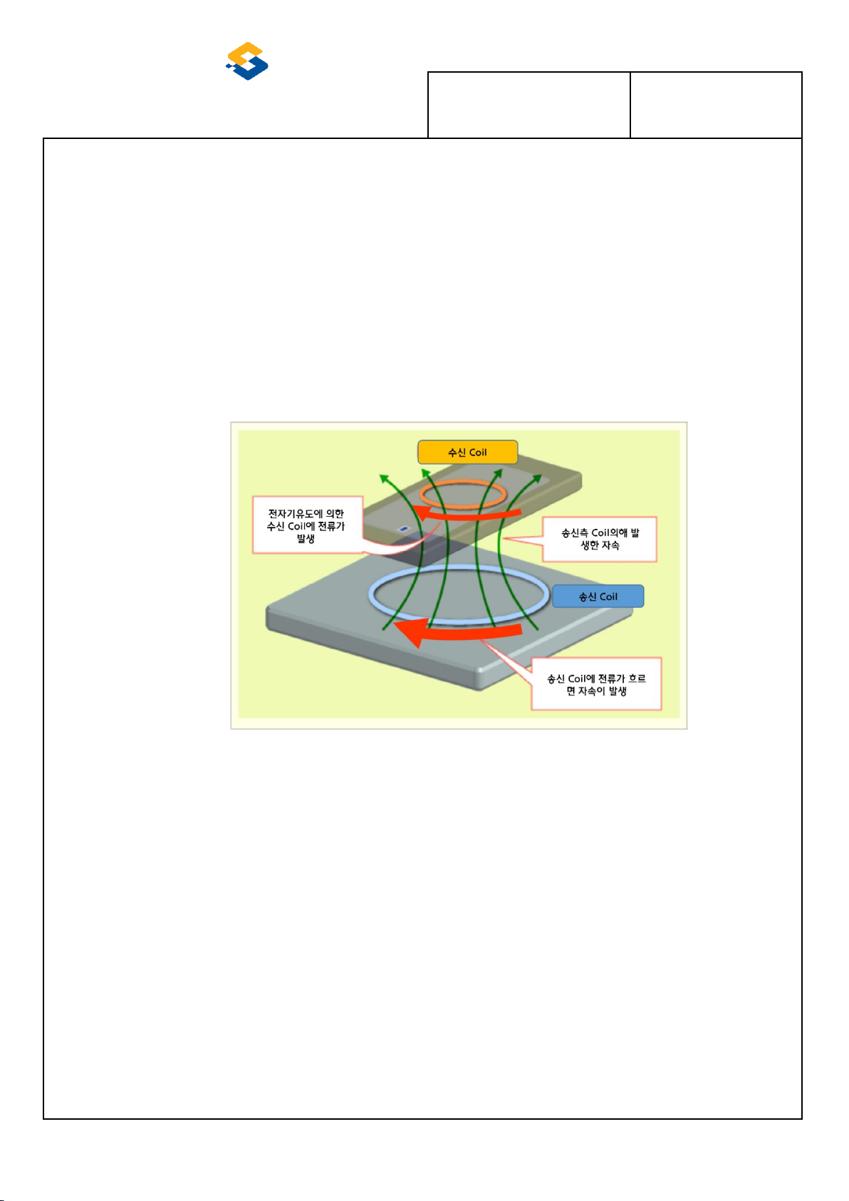
Picture 1 :OPERATION PRINCIPLE
4.2. OPERATION PRINCIPLE
WPC transmits power by magnetic induction to the overlapping area of the coil inner diameter of WPC and
the coil inner diameter of WPC with LC resonance (110KHZ).
 Loading...