

Page 1
Title : NO.
- Transmitter
- Receiver
Information Document
Date
0. GENERAL
0.1. Make
SEOYON ELECTRONICS
0.2. Model No.
Remote Keyless Entry Transmitter
SYEC3TX1612
Unit Assy-BCM & Receiver
SYECBCM1611
0.3. Name and address of manufacturer
SEOYON ELECTRONICS
424, Sinwon-ro, Danwon-gu, Ansan-si, Gyeonggi-do, Korea
0.4. Address of assembly plant
SEOYON ELECTRONICS
424, Sinwon-ro, Danwon-gu, Ansan-si, Gyeonggi-do, Korea
711, Baekseok-dong, Seobuk-gu, Cheonan-si, Chungcheongnam-do, Korea
Page 2
Title : NO.
Information
Information Document
Date
2. PRODUCT SPECIFICATION
2.1 Remote Keyless Entry System
2.1.1 KEY PART : TRANSMITTER is inside of the REMOTE KEY, and it
sends the ROLLING CODE to the RECEIVER by Radio Frequency.
2.1.2 RECEIVER : It receives the ROLLING CODE and decodes that,
thereafter RECEIVER drives the actuator.
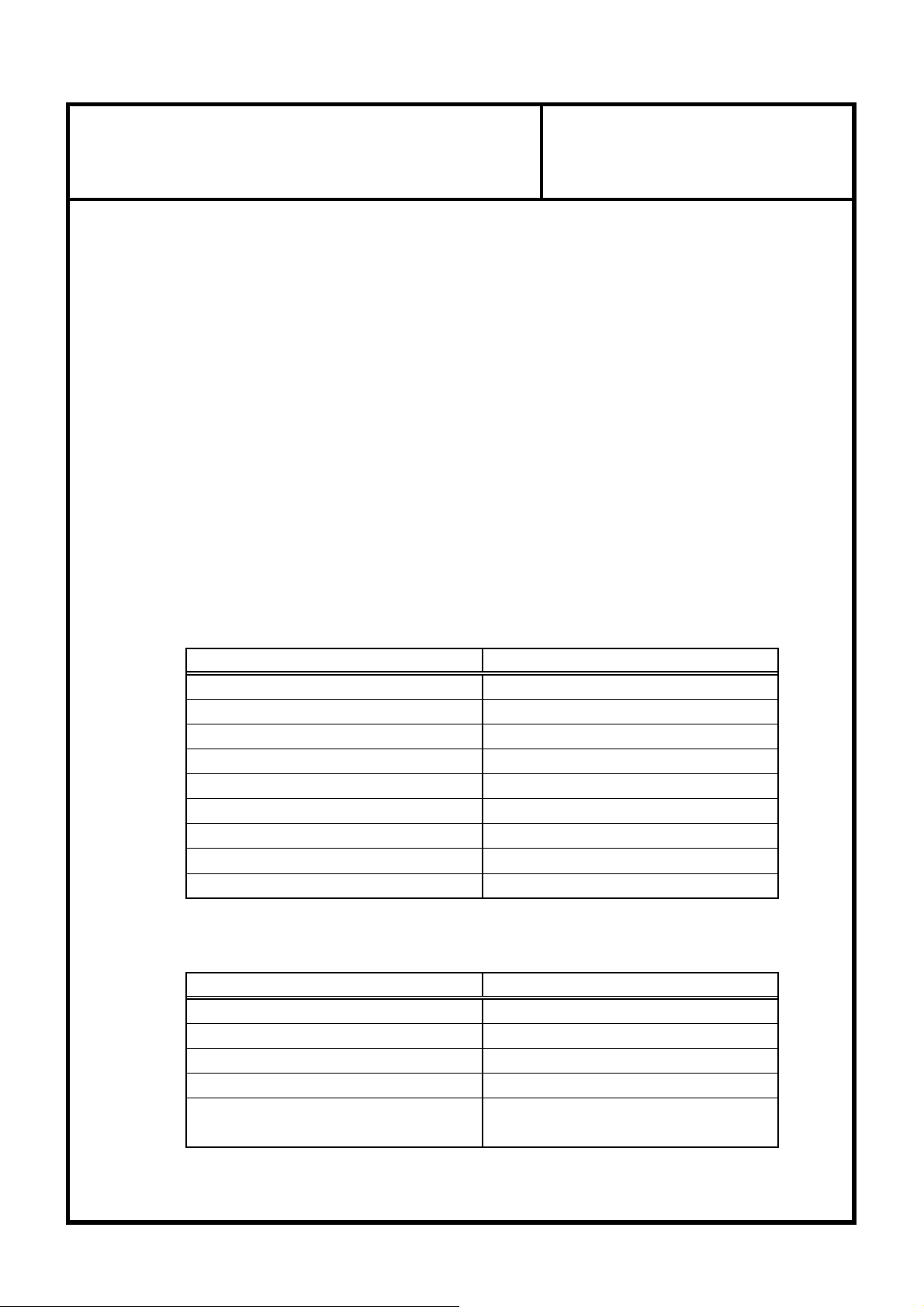
2.2 SPECIFICATIONS
2.2.1 TRANSMITTER
Rated supply voltage DC 3V
Operating voltage range DC 2.5 ~ 3.2V
Operating temperature range
Storage temperature range
Electric field strength 10mW (433.92MHz)
2.2.2 RECEIVER
Operating Temperature
Max Humidity 95%
Standby Current
ITEM
Modulation FSK
Frequency 433.92MHz
Code Rolling Code(Hopping Algorithm)
Battery life 3 Year(20Cycle/Day)(Lithium 3V 1EA)
Item
SPECIFICATION
-20 ~+60℃
-30 ~ 80℃
Specification
DC 12VRated Supply Voltage
DC 9 ~ 16VOperating Voltage
- 35 ~ + 75℃
Below than 4.0mA
(in alarm setting condition)
Page 3
Title : NO.
Information Document
Information Document
Date
2.3 Operating summary
① TRANSMITTER's button is pushed.
② TRANSMITTER sends the code by radio frequency.
③ RECEIVER gets the code and decodes it.
④ RECEIVER judges the code whether it is right code or not.
⑤ RECEIVER checks door lock or unlock Tail-Gate state.
⑥ RECEIVER drives the actuator.
2.3.1 LOCK & UNLOCK
① If LOCK or UNLOCK button is pushed for less than 1 sec, then
TRANSMITTER sends the LOCK or UNLOCK DATA.
2.4 Caution
① Danger of explosion if battery is incorrectly replaced.
② Replace only with the same or equivalent type recommended by the manufacturer.
③ Dispose of used batteries according to the manufacturer's instructions.
Page 4
Title : NO.
- RKE in BCM system is intended for auto door lock or unlock or TAIL-GATE in vehicle.
Information Document
Information Document
Information Document
Information Document
Date
3. USER MANUAL
3.1 NAME : BCM system
- This system is BCM and inculdes RKE.
- This BCM system is to be installde on motor vehicles as *OE item.
*OE : Original Equipment.
*BCM : Body Control Module.
*RKE : Remote Keyless Entry.
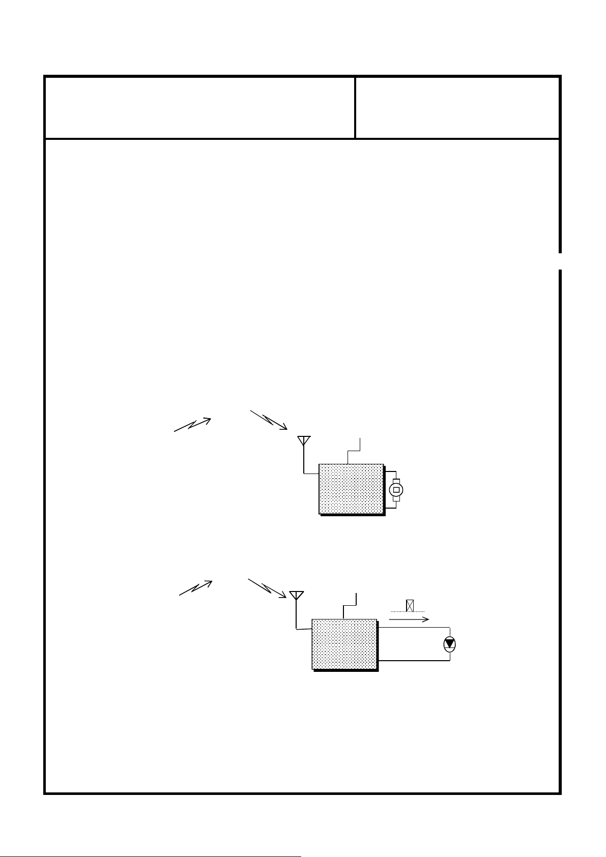
3.2 SYSTEM CONSTRUCTION
3.2.1 SYSTEM IN VEHICLE
ROLLING CODE
(433.92MHz)
3.2.2 SYSTEM FOR TEST
ROLLING CODE
(433.92MHz)
ANTENNA
ANTENNA
BATTERY
RECEIVER
BATTERY
RECEIVER
DOOR
ACTUATOR
LOCK or UNLOCK or TAIL-GATE DATA
lamp
* Through the use of lamp, operating state is displayed by lamp.
lamp 'ON' means that actuator is operated by door lock or unlock or tail-gate output signal.
Page 5

FCC Information
This device complies with part 15 of the FCC Results. Operation is subject to the
following two conditions :
(1) This Device may not cause harmful interface, and
(2) This device must accept any interference received, including interference that
may cause undesired operation.
Note: This equipment has been tested and found to comply with the limits for CLASS B digital device,
pursuant to Part 15 of FCC Rules. These limits are designed to provide reasonable protection against harmful
interference when the equipment is operated in a commercial environment This equipment generates, uses
and can radiate radio frequency energy and, if not installed and used in accordance with the instructions,
may cause harmful interference to radio communications. However, there is no guarantee that interference
will not occur in a particular installation. If this equipment does cause harmful interference to radio or
television reception, which can be determined by turning the equipment off and on, the user is encouraged
to try correct the interference by one or more of the following measures:
1.1. Reorient or relocate the receiving antenna.
1.2. Increase the separation between the equipment and receiver.
1.3. Connect the equipment into an outlet on a circuit different from that to which receiver is connected.
1.4. Consult the dealer or experienced radio/TV technician for help.
WARNING
Changes or modifications not expressly approved by the manufacturer could void the
user’s authority to operate the equipment.
“CAUTION : Exposure to Radio Frequency Radiation.
Antenna shall be mounted in such a manner to minimize the potential for human contact during normal
operation. The antenna should not be contacted during operation to avoid the possibility of exceeding the
FCC radio frequency exposure limit.
"ATTENTION: L'exposition aux rayonnements à fréquence radioélectrique.
Antenne doit être montée de telle manière à minimiser le risque de contact humain pendant l'utilisation
normale. L'antenne ne doit pas être contacté pendant le fonctionnement pour éviter la possibilité de
dépasser la limite de l'exposition aux fréquences radio de la FCC.
Page 6

IC Information
This device complies with Industry Canada license-exempt RSS standard(s). Operation in subject to The
following two conditions: (1) this device may not cause interference, and (2) this device must accept any
interference, including interference that may cause undesired operation of the device.
Le présent appareil est conforme aux CNR d’Industrie Canada applicables aux appareils radio exempts de
licence. L’exploitation est autorisée aux deux conditions suivantes:
1) l’appareil ne doit pas produire de brouillage;
2) l’appareil doit accepter tout brouillage radioélectrique subi, même si le brouillage est susceptible d’en
compromettre le fonctionnement.
 Loading...