


MMP Bluetooth / MMP/ GH570 User guide
This instruction manual is defining the interface spec for the external devices which will be
connected with this module.
1. Configuration image of the module.
This module configures the complete product by combining with the external device
having an interface specification shown below.
2. Required features of External device to be connected.
Product
Devices that are conforming to
GH570
This Module External device
the interface specification
① Get the receiving data from the Module.
② Send the transmission data to the Module.
③ Send the “RESET” command to the Module.
④ Get the status of the Module and show it.
⑤ Provide the power to the Module.
※ Any modification is NOT possible from external device against the spec of GH570
module declared on its spec sheet.
3. Connection ports of GH570
1
2
3
4
5
6
7
GH570
GND
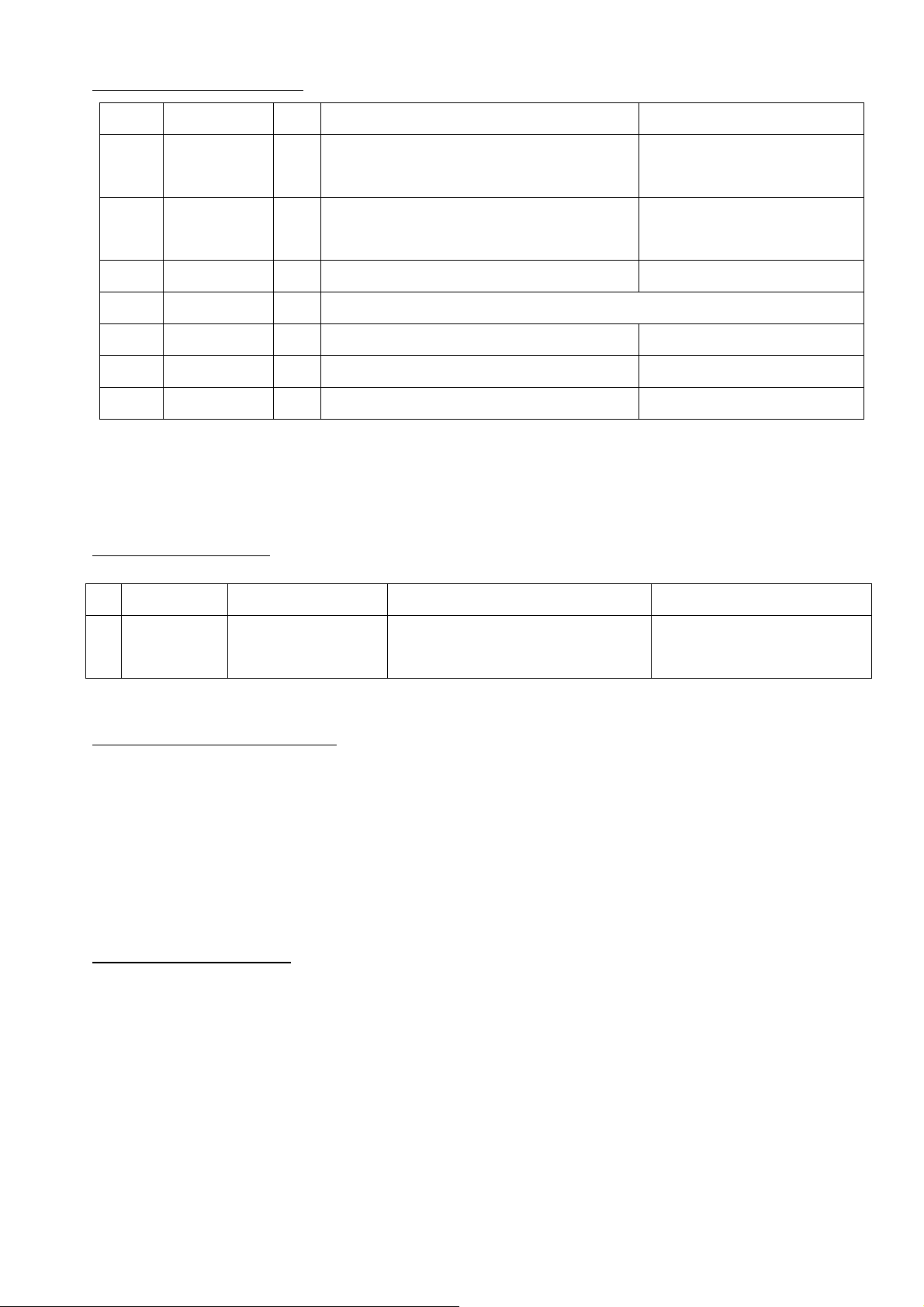
4. Functions of each port
5. Command & Status
No. Name I/O Function Remarks
1 LED2B I Bypass port for External device Used for showing
2 LED1B I Bypass port for External device Used for showing
3 VDDB I Power connector to the GH570 3.3V -0.1V +1.0V
4 P20B I To switch the drive mode H: Normal / L: HCI UART
5 RST_NB I Reset port from External device
6 BLTB I Transmission data port
7 BLRB O Receiving data port
status
status
#
Code Description Function Remarks
1 0x100111 E2PROM_Write Overwrite the ID to
EEPROM
6. Supplemental information
This module is developed for the dedicated single purpose only.
So the function of this module is limited intentionally for users. Any modification is
NOT possible from external device against the spec of GH570 module declared on its
spec sheet.
7. End Product Labeling
This transmitter module is authorized only for use in device where the antenna may be
installed such that 20cm may be maintained between the antenna and users. The final
end product must be labeled in a visible area with the following: "Contains FCC ID:
0x00: Succeeded
2AERZ-GH570 ”

8. Information for the OEMs and Integrators
The following statement must be included with all versions of this document supplied
to an OEM or integrator, but should not be distributed to the end user.
1) This device is intended for OEM integrators only.
2) Please see the full Grant of Equipment document for other restrictions.
FEDERAL COMMUNICATIONS COMMISSION INTERFERENCE STATEMENT
This equipment has been tested and found to comply with the limits for a Class B
digital device, pursuant to part 15 of the FCC Rules. These limits are designed to
provide reasonable protection against harmful interference in a residential
installation. This equipment generates, uses and can radiate radio frequency energy
and, if not installed and used in accordance with the instructions, may cause
harmful interference to radio communications. However, there is no guarantee that
interference will not occur in a particular installation. If this equipment does cause
harmful interference to radio or television reception, which can be determined by
turning the equipment off and on, the user is encouraged to try to correct the
interference by one or more of the following measures:
-Reorient or relocate the receiving antenna.
-Increase the separation between the equipment and receiver.
-Connect the equipment into an outlet on a circuit different from that to which the
receiver is connected.
-Consult the dealer or an experienced radio/ TV technician for help.
CAUTION:
Any changes or modifications not expressly approved by the grantee of this device
could void the user's authority to operate the equipment.
This device complies with Part 15 of the FCC Rules. Operation is subject to the
following two conditions: (1) this device may not cause harmful interference, and (2)
this device must accept any interference received, including interference that may
cause undesired operation.
RF exposure warning:
This equipment must be installed and operated in accordance with provided
instructions and the antenna(s) used for this transmitter must be installed to
provide a separation distance of at least 20 cm from all persons and must not be
co-located or operating in conjunction with any other antenna or transmitter.
End-users and installers must be provide with antenna installation instructions
and transmitter operating conditions for satisfying RF exposure compliance.

經型式認證合格之低功率射頻電機,非經許可,公司、商號或使用者均不得擅自變更頻率、
加大功率或變更原設計之特性及功能。
本模組於取得認證後將依規定於模組本體標示審驗合格標籤,並要求最終產品平台廠商
(OEM Integrator)於最終產品平台(End Product)上標示本產品內含射頻模組,
其 NCC 型式認證號碼為: CCXXxxYYyyyZzW
 Loading...