

MMM Medcenter CLIMACELL 111, CLIMACELL 222, CLIMACELL 404, CLIMACELL 707 Operating Instructions Manual

CLIMACELL_PCH_en_np_mmm ! 0208 V1.07_Blue Line
Cooling incubator
with controlled humidity
CLIMACELL 111, 222, 404, 707
Operating instructions
MMM Medcenter GmbH Manufacturer:
MMM Medcenter
Einrichtungen GmbH
Schulstrasse 29
D – 82 166 Gräfelfing
Tel.: +49 89 89 92 26 20
Fax: +49 89 89 92 26 30

Operating instructions CLIMACELL Page 1
CLIMACELL_PCH_en_np_mmm ! 0208 V1.07_Blue Line
CONTENTS:
2.8..2002
1 GENERAL NOTES......................................................................................................................... 3
2 IMPORTANT INSTRUCTIONS ...................................................................................................... 3
2.1 U
NPACKING AND CHECK ................................................................................................................ 3
2.2 BEFORE PUTTING INTO OPERATION ................................................................................................ 4
2.3 P
ERMITTED LOADS:....................................................................................................................... 5
2.4 WIRING AND OTHER CONDITIONS ................................................................................................... 5
3 SPECIFICATIONS OF THE COOLING INCUBATOR WITH CONTROLLED HUMIDITY............ 6
3.1 G
ENERAL VIEW ............................................................................................................................. 6
3.1.1 Useful space...................................................................................................................... 7
3.2 C
ONNECTOR RS-232C FOR PROTOCOL PRINTER .......................................................................... 7
3.3 O
PERATING PANEL........................................................................................................................ 8
4 FUNCTION AND OPERATING...................................................................................................... 9
4.1 C
ONNECTING TO THE WATER SOURCE AND DRAIN ........................................................................... 9
4.2 C
ONNECTING TO THE ELECTRIC NETWORK:.................................................................................... 9
4.3 SWITCH THE UNIT ON: ................................................................................................................... 9
4.4 GENERAL SETUP OF CLIMACELL............................................................................................... 10
4.4.1 Activating the service mode............................................................................................. 10
4.4.2 Service 01 – Storing P1 – P4, or P5, or P6 to chip card ................................................. 10
4.4.3 Service 02 – Restore/upload the programs from the chip card to the unit...................... 10
4.4.4 Service 03 – Set the real time and date.......................................................................... 11
4.4.5 Service 04 – Set interval on printer/communication interface......................................... 11
4.4.6 Service 05 – Select language.......................................................................................... 12
4.4.7 Service 06 – Setting the switching time of the inner socket (optional)............................ 12
4.4.8 Service 07 - Setting the safety thermostat ...................................................................... 12
4.4.9 Service 08 – Selecting the water quality ......................................................................... 13
4.4.10 Service 09 – Canceling the service regime..................................................................... 13
4.4.11 Setting the lighting – type with door lighting.................................................................... 13
4.4.12 Setting the relative humidity in programs P1 – P4 .......................................................... 13
4.4.13 Setting the operating conditions of temperature and relative humidity and their limitations
14
4.5 P
ROGRAM P1............................................................................................................................. 15
4.5.1 Set P1.............................................................................................................................. 15
4.5.2 LCD read out shown........................................................................................................ 15
4.5.3 Start P1........................................................................................................................... 15
4.5.4 Information on the set parameters during the device’s running:..................................... 16
4.5.5 Stop program P1.............................................................................................................. 16
4.6 P
ROGRAM P2............................................................................................................................. 16
4.6.1 Set P2............................................................................................................................. 16
4.6.2 LCD - read out shown:..................................................................................................... 16
4.6.3 Start P2............................................................................................................................ 17
4.6.4 Information on the set parameters during device’s running:........................................... 17
4.6.5 Stop P2........................................................................................................................... 17
4.7 P
ROGRAM P3............................................................................................................................. 17
4.7.1 Setting the program P3.................................................................................................... 17
4.7.2 LCD - read out shown:..................................................................................................... 18
4.7.3 Start P3........................................................................................................................... 18
4.7.3.1 P3 and segment 1 in the graph are active. ................................................................................18
4.7.3.2 P3 and segment 2 in the graph are active, the segment 1 is over............................................. 18
4.7.4 Information on the set parameters during the device’s running:..................................... 19
4.7.5 Stop P3........................................................................................................................... 19
4.8 P
ROGRAM P4............................................................................................................................. 19

Operating instructions CLIMACELL Page 2
V1.07_Blue Line
LIMACELL_PCH_en_np_mmm ! 0208
4.8.1 Set P4.............................................................................................................................. 19
4.8.2 Set the segment for T1.................................................................................................... 20
4.8.2.1 Set temperature T1 ................................................................................................................... 20
4.8.2.2 Set the delay time of T1 : .......................................................................................................... 20
4.8.2.3 Read out of T1 and the delay time: ........................................................................................... 20
4.8.2.4 Set the ramp at T1 :................................................................................................................... 20
4.8.2.5 Read out of T1 and the ramp:.................................................................................................... 20
4.8.2.6 Set the fan speed at the temperature T1:.................................................................................. 20
4.8.3 Set the temperature T2 :.................................................................................................. 21
4.8.3.1 Set the temperature T2 : ........................................................................................................... 21
4.8.3.2 Set the delay time of T2 ............................................................................................................ 21
4.8.3.3 Read out of T2 and the delay time: ........................................................................................... 21
4.8.3.4 Set the ramp at T2:.................................................................................................................... 21
4.8.3.5 Read out of T2 and the ramp:.................................................................................................... 21
4.8.3.6 Set cycles for P4: ......................................................................................................................21
4.8.3.7 Read out of cycles for P4: .........................................................................................................21
4.8.3.8 Setting the ventilator rate and RH at the temperature T2: ......................................................... 22
4.8.4 Start P4:.......................................................................................................................... 22
4.8.4.1 S1 is active, temperature is heading towards T1:...................................................................... 22
4.8.4.2 S2 is active, T1 has been reached, delay time is running: ........................................................ 23
4.8.4.3 S3 is active, temperature is heading towards T2:...................................................................... 23
4.8.4.4 S4 is active, T2 is reached, delay time at T2 is running: ........................................................... 23
4.8.5 Information on the set parameters during the device’s running:..................................... 23
4.8.6 Stop P4............................................................................................................................ 24
4.9 P
ROGRAM P5, P6....................................................................................................................... 24
4.9.1 Description of P5 and its control...................................................................................... 24
4.9.2 Description of P6 and its control...................................................................................... 26
4.10 E
RROR MESSAGES ................................................................................................................. 29
4.11 PRINTING THE PROTOCOL ....................................................................................................... 31
4.12 CHECKING THE FUNCTION OF THE SAFETY THERMOSTATS......................................................... 31
5 MAINTENANCE........................................................................................................................... 32
5.1 E
XCHANGE OF THE DOOR SEAL.................................................................................................... 32
5.2 CONTAINER FOR COLLECTING THE CONDENSED WATER STEAM...................................................... 33
5.3 C
LEANING THE COOLING INCUBATOR............................................................................................ 33
5.4 MELTING .................................................................................................................................... 33
6 TECHNICAL DATA...................................................................................................................... 34
7 WARRANTY AND SERVICE....................................................................................................... 35
8 TRANSPORT AND STORAGE.................................................................................................... 35
9 HOW TO ELIMINATE WRAPPINGS AND A UNIT OUT OFF SERVICE ................................... 35
10 OPTIONAL EQUIPMENT............................................................................................................. 36
10.1 I
NNER LIGHTING...................................................................................................................... 36
10.2 BUSHINGS OF DIAMETER 25, 50, 100 MM ................................................................................ 36
10.3 L
OCKABLE DOOR .................................................................................................................... 36
10.4 LEFT DOOR ............................................................................................................................ 36
10.5 I
NDEPENDENT SENSOR PT100................................................................................................ 36
10.6 COMMUNICATION SW DS COM FOR PC UNDER WINDOWS ...................................................... 36
10.7 POTENTIAL-FREE CONTACT FOR ALARM REPORTS .................................................................... 37
10.8 T
HE INNER SWITCHED SOCKET ................................................................................................ 37
10.9 E
XPOSITION LIGHTING IN THE DOOR......................................................................................... 37

Operating instructions CLIMACELL Page 3
CLIMACELL_PCH_en_np_mmm ! 0208 V1.07_Blue Line
1 General notes
The unit CLIMACELL should be used in applications, in which changing the temperature in a
sample in range from 0 °C to 99.9 °C and the relative humidity (RH) from 10 % to 95 % in
various time modes is needed.
CLIMACELL may be used in several ways, so please, read this manual carefully.
MMM’s cooling incubators CLIMACELL are equipped with a microprocessor control with the
following features:
1. Fuzzy-logic temperature controller and a thermo-sensor PT 100.
2. Humidity control by PID regulator with fuzzy logic and a humidity capacity sensor.
3. 4 preset programs P1 to P4, 2 programs P5 and P6 to set containing up to 16 steps.
4. Electronic timer with different time modes, see description of programs (page 10).
5. Adjustable fan speed from 0 to 100 % in 10 %-steps.
6. Printing the protocol with real temperature and time values via interface RS 232 C.
7. Chip card reader to store data P1 to P4, P5, P6 and to record to the memory .
8. Foil covered touch buttons for easy programming.
9. 32 digit LCD display, illuminated. All parameters seen at once. (To your information, the
display is already set up to be used in product ranges coming out in future.)
CLIMACELL is manufactured of high grade materials with the latest technology and is
subjected to strict final tests leaving the plant. The inner chamber housing as well as the
shelves are made of stainless steel. The coating is water based, gray on top of galvanized
zinc coated sheet metal, safe for the environment.
2 Important instructions
2.1 Unpacking and check
After unpacking the unit, please, check, whether the unit and its facilities are complete and
undamaged.
An eventual damage must be immediately reported to the transporting company.
During the manipulation – in case of lifting the cabinet etc. – the cabinet cannot be hold by
the rail or door. The cabinets of volumes 404 and 707 should be lifted by means of delivered
hooks, the rolls are designed for local moving, not for longer transport.
The standard delivery consists of the temperature cabinet,
two sieves,
one chip card SO for setting the safety thermostat,
three chip cards for storing the set programs
hose for connecting the input water
(order No.: 0671574),
hose for outlet of the waste water
(order No.: S461200),
dish for collecting the condensate

Operating instructions CLIMACELL Page 4
V 1.07_Blue Line CLIMACELL_PCH_en_np_mmm ! 0208
2.2 Before putting into operation
CLIMACELL is designed and produced in accordance with EN 50081-1, 55011, 50082-2,
61000-4-2, 61000-4-4, ENV 50140, 50141, meets requirements of EU directions
89/336/EEC, 73/23/EEC, and is individually tested according to EN 61010-1.
♦
Before starting the work with this unit please study the instructions for use
carefully!
♦
Lay the treated material only on the sieves in the unit, never on the bottom of the
chamber!
♦ Carrying capacity of the floor, where the unit will be placed, must correspond to the
weight of the unit itself plus the weight of the maximum charge (see chapter Technical
parameters).
♦
The unit must not be placed on a floor covering, which could cause a danger of fire
or smothering in case of falling of hot objects out of the unit.
♦
No inflammable, explosive or toxic stuff or materials which could give such
stuff off may be inserted into the units!
♦
Unit is not designed for warming of liquids.
♦
Units are not designed for using in atmosphere with danger of inflammable or
explosive anaesthetics.
♦
Every mounting and demounting of the unit’s parts may be carried out only
after disconnecting the unit from the mains by pulling the supply cord out of the
socket.
♦ Installation of the unit is carried out by connecting to the mains and connecting to the
water source and the drain. Parameters of the electric connections are specified in
chapter Electric installation and other conditions.
♦
If the unit is not used for a longer time, disconnect it from the mains by pulling the
connecting cord out of the socket.
♦
The mains cord must not come into contact with hot parts of the unit
♦
Protection of the temperature cabinet, its surroundings and the treated material from
surpassing the temperature is secured by a safety thermostat. The unit CLIMACELL has
a safety thermostat class 3 according to EN 61010-2-010.
♦
Check the function of the safety thermostat regularly – every day (see paragraph
Check of the function of the safety thermostat).
♦
The types of cabinets are: standing on the floor, space saving, equipped with rolls
and a brake. It is necessary, that the cooling incubator stands on an even floor.
Otherwise the unit’s run could be influenced negatively.
♦
Minimum distance of the rear and side wall of the unit from other objects and walls
is 100 mm, from the upper wall it is 400 mm.

Operating instructions CLIMACELL Page 5
CLIMACELL_PCH_en_np_mmm ! 0208 V1.07_Blue Line
♦ Shifting the upper sheet of the inner chamber out and in must be carried out
carefully, there is a danger of cutting the chamber seal through as a consequence of
careless manipulation.
♦
If the unit operates with a temperature higher than 70°C, take a special care when
opening the door. As there is the set RH kept in the chamber, hot steam is generated,
which can cause a scald.
♦
As Climacell is connected to water supply and drain, place the unit in a room with
its floor sloping towards the drain.
2.3 Permitted loads:
size weight [kg]/tray total weight [kg]
55 20 50
111 20 50
222 30 70
404 30 100
707 50 130
2.4 Wiring and other conditions
• overvoltage category: II
• protection : IP 20 according to EN 60 529
• power supply: 230 V, ±10 %
• degree of grounding : 2 according to IEC 664
• ambient temperature: 4 to 40 °C
• relative humidity: 80 % at 31 °C, 50 % at 40 °C
• use: interior rooms
• separation of external circuits double isolation, the circuits are separated
from the mains by a safety transformer
tested for the voltage 2300 V
Operating instructions CLIMACELL Page 6
V 1.07_Blue Line CLIMACELL_PCH_en_np_mmm ! 0208
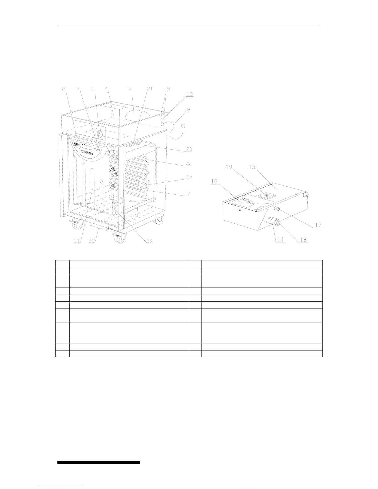
3 Specifications of the cooling incubator with controlled humidity
3.1 General view
1 Mains switch 12 Quick coupler – ring for disconnecting
2 Control panel 13 Quick coupler – part I
3 Plastic body of the regulator 14 Unit of the magnetic treatment of input water
from the distribution system
4 Condenser 15 Boiling vessel for steam generator
5 Compressor (coolant R134a) 16 Pump
6 Cooling snakelike tubing – 6a, 6b 17 Drain of waste water
7 Heating bodies in the heating space 18 Input of pressure water of the distribution
from the vessel with distilled water
8 Mains connector. 230V, 50 Hz 19 Interconnection of the generator and the
chamber (with sealing)
9
Fuses, F 10 A, 250 V, ∅ 5 x 20 mm
20 Sensor PT 100
10 Interface for printing the protocol (RS 232C) 21 Relative humidity sensor
11 Exposure lighting in the door – option 22 Set of the steam generator
Operating instructions CLIMACELL Page 7
CLIMACELL_PCH_en_np_mmm ! 0208 V1.07_Blue Line
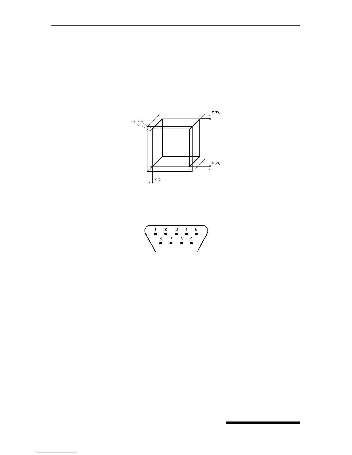
3.1.1 Useful space
Useful space - see the illustration. in the following picture, where X(H) = X(D) = 10 % of the
chamber depth, X(Š) = X(W) = 10 % of the chamber width, X(V)
1
= X(H) = distance of the
bottom shelf to the bottom of the chamber. The required temperature accuracy from the par.
Technical parameters can be only achieved within the space defined above(according to DIN
12 880 – marked with heavy lines in the picture, the light lines mark the inner walls of the
chamber). (It means that over the highest shelf the values of the chapter Technical
parameters are not obligatory).
3.2 Connector RS-232C for protocol printer
Interface parameters
Baud: 4800
Stopbit: 1
Parity: none
Databit: 8
Devices connected with of connector RS 232 must fulfill valid regulations and be
approved by a competent testing laboratory.
The unit is designed for connecting to printer CITIZEN, model iDP 3110-24 RF-A, which
can be ordered optionally.
Pin Signal
2TxD
3RxD
5GND
6DSR
Operating instructions CLIMACELL Page 8
V 1.07_Blue Line CLIMACELL_PCH_en_np_mmm ! 0208
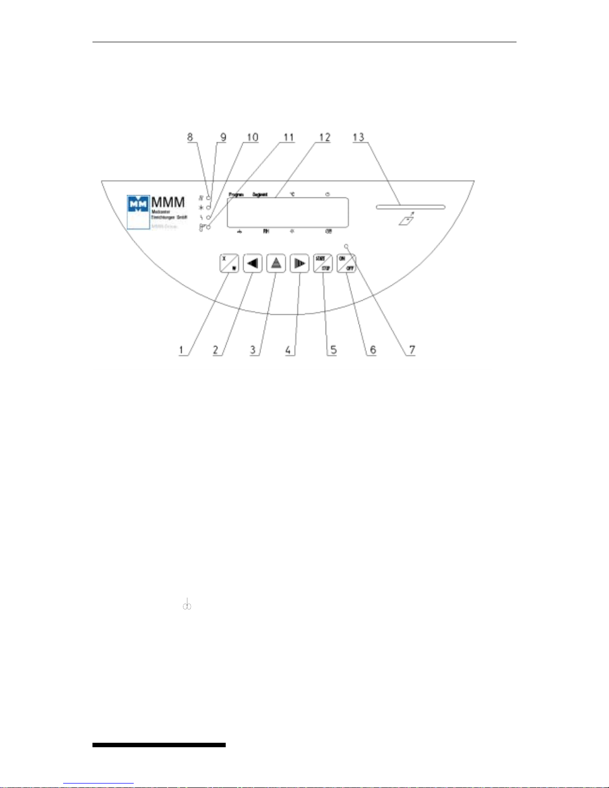
3.3 Operating panel
1 key of activation of setting-up mode
2/4 cursor steering turning to the left/right
3 setting-up value in parameter
5 key starting the program
6 switch (ON - on, OFF - stand by)
7 indicator light - shines after switching on the switch
8 indicator light heating - shines: state of temperature regulator - heating active
9 indicator light cooling - shines: state of temperature regulator - cooling active
10 indicator light – failure
11 indicator light of safety thermostat - shines: temperature surpassed the limit set on the safety
thermostat - heating is off / see paragraph 4.1.8 Set safety thermostat
12 Display
13 port for inserting the chip card
Segment: partial or full graphic representation of the program coarse
Segment : l’affichage graphique du parcour du programme parciel ou total
°C: temperature display
": process time
: fan speed display in % (steps of 10 %)
RH – relative humidity
☼ - setting-up intensity of exposition light in the door
56 -
p
ositions are used for specific purposes - see descriptions in text

Operating instructions CLIMACELL Page 9
CLIMACELL_PCH_en_np_mmm ! 0208 V1.07_Blue Line
4 Function and operating
Function of individual indicator lamps and control keys is described in chapter
Description of the unit in paragraph Control panel.
4.1 Connecting to the water source and drain
a) the water source is a plastic container (ca. 50 l) with a submersible pump, filled with
distilled water
Unpack the container and:
- connect the cable connector to the corresponding socket in the rear part of the upper
piece (side piece) of Climacell,
- connect the hose to the steam generator (which is placed outside the unit at the bottom)
by means of the inner thread hose coupling to the container .
- Fill the container with distilled water. Climacell is ready for operation.
b) the water source is a drinking water piping (Ca content is max. 50 mg/l), permissible
water pressure is in the range from 0.1 to 1 MPa
By means of the supplied plastic hose connect CLIMACELL to the common water piping in
following way: screw one screw joint to the inlet pipe, which leads from the steam generator,
and the other screw joint to the water piping outlet. There is a unit of magnetic water
treatment placed on the steam generator inlet pipe ; the treatment suppresses forming of
mineral deposits inside the generator. Fix one end of the supplied outlet hose to the outlet
pipe, before which the waste water pump is placed, and tighten it with a tape, lead the other
end to a basin or directly to the drain. Taking the connection of Climacell to the water and
drain into consideration, it is recommended to place Climacell in a room with a floor sloping
towards the drain.
Caution!
In both cases a) and b) the hose of the water supply or discharge from the steam generator
must not be bent, throttled or cranked so that water cannot flow.
4.2 Connecting to the electric network:
Compare the nominal voltage and power input values, which you can find on the product
plate, with the power supply. If the supply parameters comply with the unit’s parameters,
connect the plug to the supply socket.
4.3 Switch the unit on:
Set the mains switch, which is placed on the panel of exceeding port, to the I position. Press
the
, (the control light above the switch comes on), display comes on and the device is
ready for running. Continue the procedure as follows.
LCD shows all parameters for your convenience at once. Cursor is placed below all 32 digits
of LCD in a so called cursor line and is always placed only below one of the digits
Cursor line
(32 digits)

Operating instructions CLIMACELL Page 10
V 1.07_Blue Line CLIMACELL_PCH_en_np_mmm ! 0208
Parameter change:
Move the cursor horizontally by pressing ◄► . Change the parameter above the cursor by
pressing ▲.
4.4 General setup of CLIMACELL
CLIMACELL – MMM’ s product – offers a wide range of customer’s benefits. In order to
make them active, there are fundamental inputs required. To achieve this the following
service mode containing 7 different services is here.
4.4.1 Activating the service mode
Press simultaneously buttons ▲► for 2 seconds. LCD shows Service 01. By pressing the
button ▲ you can change between the single service modes Service 01 – Service 08.
4.4.2 Service 01 – Storing P1 – P4, or P5, or P6 to chip card
With help of this service you can store programs P1 – P4, or P5, or P6 on the MMM s chip
card. Before storing the parameters to the chip card it necessary to insert the right card to the
unit panel. These cards can be ordered optionally.
Make sure that the chip card is in the card reader!
Press START/STOP to do storing. The transmission is confirmed by the read out „Done“ on
LCD. Press START/STOP again to enter another service. If the read out on the LCD is „Bad
MMM CCard“, check the chip card and repeat the procedure.
Pressing START/STOP enter the program storing service at first.
The choices P1 – P4,or P5 or P6 are available. Select by pressing ▲ .
To store the program press button
.
(In detail: Before the start: the display indicates: „Service 01“
„Save to CCard“
After the start: on the second line of the display by pressing ▲ select what will be saved on
the chip card. Choices
- all eligible parameters of P1 to P4 at once - the display indicates:
„P1÷4 →MMM CCard“,
- all eligible parameters of P5 - the display indicates: „P5→MMM CCard“,
- all eligible parameters of P6 - the display indicates: „P6→MMM CCard“.
The storing of your choice on the chip card is done by pressing
If an incorrect card is
placed into the unit, the display indicates: “Bad MMM CCard“. If everything is all right, the
indication is: “Done“.)
Quit the service by pressing START/STOP again.
4.4.3 Service 02 – Restore/upload the programs from the chip card to the unit
With help of this service you can record the programs P1 – P4, or P5, or P6 stored on the
chip card again to the unit’s memory (see 3.1.2). The programs in the memory will be
recorded over (erased). Make sure the chip card is in the card reader. Press START/STOP
to record. The transmission is confirmed by the read out „Done“ on LCD. Press
START/STOP again to enter another service. If the read out on the LCD is „Bad MMM
CCard“, check the chip card and repeat the procedure.

Operating instructions CLIMACELL Page 11
CLIMACELL_PCH_en_np_mmm ! 0208 V1.07_Blue Line
The procedure is as follows: By pressing START/STOP you enter the program restoring
service at first. The choices P1 – P6 are available. Select by pressing ▲. To record the
program press button
.
(In detail: Before the start: the display indicates: „Service 02“
„Load from CCard“
After the start: on the second line of the display by pressing ▲ select what will loaded from
the chip card. Choices:
- all eligible parameters of P1 to P4 at once - the display indicates:
„MMM CCard→P1÷4“,
- all eligible parameters of P5 - the display indicates: „MMM CCard → P5“,
- all eligible parameters of P6 - the display indicates: „MMM CCard →P6“.
The loading of your choice from the chip card is done by pressing
If an incorrect card is
placed into the unit, the display indicates: “Bad MMM CCard“. If everything is all right, the
indication is: “Done“.)
Quit the service by pressing START/STOP again.
Caution!
Use only an original chip card delivered by the producer. Using of another card could
cause damaging of your unit’s regulator and the guarantee would be cancelled.
4.4.4 Service 03 – Set the real time and date
Pressing START/STOP you enter the service. Set the real time and date by pressing buttons
◄► and ▲ . To quit the service press START/STOP again. Data on the display are in the
following form: ho:mi_day:month:year
4.4.5 Service 04 – Set interval on printer/communication interface
To print protocols device can be set up (optional) with a printer CITIZEN iDP 3110-24 RF-A,
which is connected by a cable to the printer interface – see par. Printing the protocol. Enter
the service by START/STOP and set the interval:
Pressing ▲ select one of the following choices:
printer off
switched over to PC (application of SW DS Com – data are sent to PC)
interval 10 s
interval 01 min
interval 01 h
By pressing ◄ move the cursor to the position 10/01 seconds, minutes or hours. By pressing
▲ you can change the printer interval within the following range:
10 to 50 s (step 10 s)
01 to 59 min (step 1 min)
01 to 12 h (step 1 h)
To quit the service press START/STOP again.
.
Caution!
Only one unit is active, either seconds, minutes, or hours!
 Loading...