

MMM Group ECOCELL 404, ECOCELL 55, ECOCELL 707, DUROCELL 55, DUROCELL 22 Instructions For Use Manual
...
Instructions for use
Laboratory drying ovens and incubators
line Comfort
LSI_K_np_en 1206_mmm_V2.08_B2V
ECOCELL 22, 55, 111, 222, 404, 707
DUROCELL 22, 55, 111, 222
VENTICELL 22, 55, 111, 222, 222/2, 404,
404/2, 707, 707/2
INCUCELL 22, 55, 111, 222, 404, 707
INCUCELL V 22, 55, 111, 222, 404, 707

Congratulations on obtaining a new temperature cabinet, designed for uniform tempering of various
materials by hot air at a selectable temperature and a selectable time mode in laboratories. There is an
air ap installed that enables wet material drying. The temperature course is controlled by an advanced
microprocessor (Fuzzy logic) with a digital display and a temperature sensor PT 100. This system
ensures high accuracy of temperature regulation and tempering process reliability.
The units meet technical and legislative requirements and they are designed according to respective
EN standards. The units are made of high quality materials by using the latest technology. Each piece
undergoes a careful output control.
Provided you will follow the instructions mentioned here the unit becomes your reliable and powerful
partner.
Now these advantages will be available just for you. This unit will help to solve your everyday
problems and it will become powerful assistant for you. This unit is very easy to use, nevertheless, we
recommend you to read the Instructions for use carefully so that you could use all advantages of this
unit and obtain complete knowledge for its optimal use.

CONTENTS:
26. 6. 2012
1 GENERAL................................................................................................................................3
1.1 PurPose and use...............................................................................................................................3
2 IMPORTANT INSTRUCTIONS...........................................................................................................3
2.1 unPacking, checking
and transPort...................................................................................................3
2.2 Pre installation................................................................................................................................3
2.3 useful sPace....................................................................................................................................4
3 DESCRIPTION OF THE OVEN..........................................................................................................5
3.1 general view....................................................................................................................................5
3.2
Power connetion and connectors
......................................................................................................6
3.3 control Panel..................................................................................................................................6
4 FUNCTION AND OPERATING..........................................................................................................7
4.1 Basic setting of the units................................................................................................................7
4.1.1 activating the service mode.....................................................................................................7
4.1.2 service 01 - storing P
1 - P6....................................................................................................7
4.1.3 service 02 - restore/uload the Programs from the chiP card.................................................7
4.1.4 service 03 - set the real time and date...................................................................................8
4.1.5 service 04 - set interval on Printer/communication interface.................................................8
4.1.6 service 05 - select language..................................................................................................8
4.1.7 service
06 -
setting the switching times of inner socket (oPtional)
and the fan run after the Programme termination...............................................................8
4.1.8 service 07 - safety thermostat setting.....................................................................................9
4.1.9 service
41 -
temPerature tolerance.........................................................................................9
4.1.10
service
58 -
door Blocking.
..................................................................................................10
4.1.11 service 62 - sounds setting...................................................................................................10
4.1.12
service
64 -
Programme P6 shifting
.........................................................................................10
4.1.13 service 09 - cancel the service mode.....................................................................................10
4.2 P
rogram P
1....................................................................................................................................10
4.2.1 set P
1...................................................................................................................................10
4.2.2 lcd - read out shown.............................................................................................................11
4.2.3 s
tart P
1................................................................................................................................11
4.2.4 information on the set Parameters during running...............................................................11
4.2.5 stoP P
1.................................................................................................................................11
4.3 Program P
2....................................................................................................................................11
4.3.1 set P
2...................................................................................................................................11
4.3.2 lcd - read out shown.............................................................................................................11
4.3.3 start P
2................................................................................................................................11
4.3.4 information on the set Parameters during oPeration of the unit............................................12
4.3.5 stoP P
2.................................................................................................................................12
4.4 Program P
3....................................................................................................................................12
4.4.1 set P
3...................................................................................................................................12
4.4.2 lcd - read out shown.............................................................................................................12
4.4.3 s
tart P
3................................................................................................................................12
4.4.3.1 P3 and segment 1 in the graPh are active......................................................................12
4.4.3.2 P3 and segment
2
in the are active, the segment
1
is over.............................................12
4.4.3.3 P3 and third segment in the graPh are active............................................................13

4.4.4 information on the set Parameters during oPeration of the unit............................................13
4.4.5 s
toP P
3................................................................................................................................13
4.5 Program P
4...................................................................................................................................13
4.5.1 set P
4..................................................................................................................................13
4.5.2 set the segment for t
1........................................................................................................13
4.5.2.1 set temPerature t
1 ...................................................................................................13
4.5.2.2 set the dwell time of t
1..............................................................................................14
4.5.2.3 read out of t1 and the dwell time...............................................................................14
4.5.2.4 set the ramP at t
1.......................................................................................................14
4.5.2.5 read out of t1 and the ramP...................................................................................14
4.5.2.6 set the fan sPeed at the temPerature t
1......................................................................14
4.5.3 set the segment for t
2.........................................................................................................14
4.5.3.1 set the temPerature t
2...................................................................................................14
4.5.3.2 set the dwell time of t
2..............................................................................................14
4.5.3.3 read out of t2 and the dwell time...............................................................................14
4.5.3.4 set the ramP at t
2.............................................................................................................14
4.5.3.5 read out of t2 and the ramP........................................................................................14
4.5.3.6 set cykles for P
4.............................................................................................................15
4.5.3.7 read out of cycles for P
4.......................................................................................15
4.5.3.8 set the fan sPeed at t
2....................................................................................................15
4.5.4 start P
4...............................................................................................................................15
4.5.4.1 s1 is active, temPerature is heading towards t
1.........................................................15
4.5.4.2 s2 is active, t
1
has Been reached, dwell time is running.............................................15
4.5.4.3 s3 is active, temPerature is heading towards t
2.........................................................15
4.5.4.4 s4 is active, t
2
is reached, dwell time at t
2
is running................................................16
4.5.5 information on set Parameters during oPeration of the unit...............................................16
4.5.6 stoP P
4.................................................................................................................................16
4.6 Program P
5.................................................................................................................................16
4.6.1 descriPtion of P
5
and its control.......................................................................................16
4.7 Program P
6.................................................................................................................................17
4.7.1 descriPtion of P
6................................................................................................................17
4.7.2 Programme setting...............................................................................................................18
4.7.3 Programme start.................................................................................................................19
4.7.4 Power suPPly failure...........................................................................................................19
4.7.5 automatic shifting of P6 Programme during cycling..........................................................19
4.7.6 manual shifting of P6 Programme Beginning - user service
64...............................................20
4.7.7 examPles of P6 Programme setting....................................................................................20
4.7.8 summer/winter time..............................................................................................................21
4.8
measured variaBles disPlay during the Programme run.............................................................21
4.9
keyBoard Blocking.......................................................................................................................21
4.10 error messages..........................................................................................................................21
4.11 Printing the Protocol.................................................................................................................22
4.12 adjusting and function of the air flaP........................................................................................22
4.13 exchanging the door adjusting the door....................................................................................23
5 PARAMETERS OF THE UNIT..........................................................................................................24
5.1 electric connections..................................................................................................................25
6 CLEANING AND DECONTAMINATION OF THE UNIT.................................................................25
7 MAINTENANCE......................................................................................................................26

8 WARRANTY AND SERVICE...........................................................................................................26
9 TRANSPORT AND STORAGE........................................................................................................26
10 THE WAY OF LIQUIDATION OF PACKAGE AND DISCARDED UNIT...................................27
11 OPTIONAL EQUIPMENT..................................................................................................................27
11.1 door with window and inner lighting (for all the tyPes of the volume of
22)...............................27
11.2 Bushings of diameter
25, 50, 100
mm..............................................................................................27
11.3 lockaBle door............................................................................................................................27
11.4 left door...................................................................................................................................28
11.5 indePendent sensor Pt
100 ...........................................................................................................28
11.6 suPPortive sw for Pc...............................................................................................................28
11.6.1 recording sw - warmcomm - for Pc under windows........................................................28
11.6.2 recording Printing sw - Printer archiv - for Pc under windows...........................................28
11.7 h
ePa filter................................................................................................................................28
11.7.1
Placing the hePa filter, filter dimensions, function and filtration
characteristic of the air filter
...........................................................................................28
11.8 Potential - free contact for alarm rePorts...............................................................................29
11.9 inner switched socket...............................................................................................................29
11.10
devices with the door Blocking function
..................................................................................30
11.10.1 one-door model.................................................................................................................30
11.10.2 two-door venticell.................... ........................................................................................30
11.11 Protection of Programme setting By means of a chiP card.........................................................30
11.12 door oPening signalling.............................................................................................................30
11.13 two-door Pass-through model..................................................................................................30
11.13.1 venticell
222/2
- installation data........................................................................................30
11.13.2 venticell
404/2
- installation data........................................................................................31
11.13.3 venticell
707/2
- installation data........................................................................................32
11.14 adjustment to Prevent cultivating media and tissue cultures drying.........................................33
11.15 ic and icv with decontaminating function..................................................................................33
11.16 venticell with sterilization function........................................................................................33
11.16.1 Basic sterilization Programme ss.....................................................................................33
11.16.1.1 ss Programme setting
.................................................................................................33
11.16.1.2 lcd - read out shown............................................................................................33
11.16.1.3 ss Programme start.............................................................................................33
11.16.1.4 information on the set Parameters during oPeration of the unit.......................34
11.16.1.5 stoP ss..................................................................................................................34
11.16.1.6 sterilization Programme setting and course.........................................................34
11.16.2 sterilization Programme sP with Preheating Phase..........................................................35
11.16.2.1 sP Programme setting
.................................................................................................35
11.16.2.2 segment setting for t
1..........................................................................................35
11.16.2.3 segment setting for t
2..........................................................................................35
11.16.2.4 sP Programme start..............................................................................................35
11.16.2.5 information on the set Parameters during oPeration of the unit.........................36
11.16.2.6 stoP sP..................................................................................................................36
11.16.3 two-door Pass-through model with automatic door Blocking........................................36
12 EMERGENCY DOOR OPENING.....................................................................................................37
APPENDICES:
EC - DECLARATION OF CONFORMITY


1 general
The ovens with electric heating are designed for
laboratories, generally for a warming of various
materials by means of hot air at adjustable
temperature and optional time. The air ap
enables drying of wet material.
A modern microprocessor (Fuzzy - logic) with
a digital display and PT 100 controls the
temperature. Thus exact temperature accuracy
and process safety are guaranteed. The ovens
are designed according to EN standards. They
are manufactured of high grade materials with
the latest technology. Each oven is subjected to a
strict nal test leaving the plant.
1.1 PURPOSE AND USE
ECOCELL (EC) serves for warming by hot air
with natural circulation. The ovens are designed
for temperatures up to 250 °C. They work quietly
with lower power consumption compared with VC
units.
DUROCELL (DC)
serves for warming by hot air
with natural circulation (usefull at procedures
as acid hydrolysis, extraction by nonammable
solvents, thermolysis). The ovens are designed
for temperatures up to 125 °C. Inner surfaces
of the chamber are covered with an EPOLON
layer which protects the chamber from corrosion
caused by liquid or gaseous acids in case they
leak accidentally from closed vessels. For other
important information see the chapter Before
Putting into Operation.
VENTICELL (VC) serves for warming of
materials by means of hot air with forced-air
circulation by a fan. The ovens are designed for
temperatures up to 250 °C, another variant (+)
up to 300 °C.
INCUCELL (IC, ICV) serves as an incubator or
for cell cultivation in a microbiological laboratory
(see chapter 11 - Optional equipment, article
Adaptation against drying-up of cultivating
mediums and tissue cultures). The ovens are
designed for temperatures up to 70 °C. A quiet
operation is characteristic for the variant IC
(without a ventilator), more accurate temperature
regulation with small deviations is characteristic
for the variant ICV (with ventilator).
2
important
instructions
2.1
UNPACKING, CHECKING AND
TRANSPORT
Please check after unpacking the oven and its
accessories are complete and not damaged.
A possible damage is to be reported to the
forwarding agent. During the manipulation – in
case of lifting the cabinet etc. – the cabinet
cannot be hold by the rail or door. The cabinets
of volumes 404 and 707 should be lifted by
means of delivered hooks, the rolls are designed
for local moving, not for longer transport.
A standard delivery includes the heating cabinet,
2 sieves, 3 chip cards for programme saving, and
1 special operations (SO) card.
2.2
PRE - INSTALLATION
• Please read carefully the Instructions for
use before working with the oven!
• Ovens are designed to be operated indoor
within ambient temperatures from 5 °C to
40 °C and at maximum relative humidity 80 %.
• Install the unit by plugging the power
cord to the mains. However, make sure
at rst that the mains and the electric
connection parameters correspond to the
values specied on the unit type label
and to the data shown in chapter 5 - Unit
Parameters.
• In case of temperatures above 100 °C a
yellowed stain of the inner chamber walls
can occur. This stain is neither the material
nor the unit’s defect.
• After the rst switching-on of the unit the
heating bodies and insulation start to be
baked with a typical a smell; after a few
operation cycles this smell disappears,
nevertheless it is suitable, during the
insulation baking at a temperature above
100 °C, to secure a sufcient air exchange
(e.g. by ventilation or exhaustion).
The air exhaust in VC and EC types is
protected by a cover rear of the unit. This
cover is placed inside the oven while
shipping. When installing the unit, insert the
cover into the horizontal openings bellow
and above the exhaust to attach it behind
the exhaust.
Instructions for use
LSI_K_np_en 1206_mmm_V2.08_B2V 3
DC-type – regarding the fact that it is the
inner chamber only which is resistant to
corrosive effects, the following must be
ensured during the application:
a) Processes specied in the previous
chapter must be performed in the chamber
in closed vessels (corrosive substances
release into the chamber must be
prevented);
b) Exhalations from the exhaust outlet must
be exhausted actively to prevent vapour
condensation on the outlet and its dripping
down to the electric part of the device;
c) The whole device must be placed in a
no-corrosive atmosphere (damage of the
source and regulation electronics must be
prevented).
The oven should be installed with a 100
mm distance to the walls at the side and
in back. The temperature of the air coming
out of the exhaust may be up to 250 °C
(resp. 300 °C), so the walls near the oven
must be inammable
. No inammable
or explodable materials may be put into
ovens !
Carrying capacity of the oor during
installation of the device must correspond
to the weight of the unit itself taking
the weight of the maximum charge into
consideration (see chapter 5 - Parameters
of the unit).
The unit must not be placed on a pad that
could cause a danger of re or smothering
in case of falling some hot object out of the
cabinet.
No inammable, explosive or toxic materials
may be put into ovens! The same applies to
materials that could give off such a stuff!
Goods are only to be put on trays into ovens,
never directly on the bottom of the oven!
No dangerous goods are permitted. Ovens
may not be used for heating of liquids.
Aparatus may not be used in the
atmosphere with a possible danger of
ammable or explosive anesthetics.
Any assembly and disassembly of the
unit parts may only be done after the
unit disconnection from the mains
(unplugging the power cord or switching
the main switch off – see chapter 5)! If
the unit is switched off (button 6, Fig. 4),
the unit will be ready-to-start only but it
is not disconnected from the mains!
• If the oven is not used for a longer time,
disconnect it from mains by pulling the
service cord from the socket.
Power cord can not get to the contact with
hot parts of the aparatus – protection cover
of exhaust hole.
• The temperature cabinet, its surroundings
and the treated material are protected
against an inadmissible temperature
overrun by means of a safety thermostat.
Pull out and consequently push in the
upper metal plate piece of internal chamber
carefully, there is a danger of cutting
through the rubber gasket of the chamber
during careless manipulation.
The maximum permitted loads: see section
5 - Parameters of the unit.
When operating the cabinets at high
chamber temperature there can be the
maximum allowed temperature of 70 °C at
their outer surface (exhaust ports and their
surroundings and the surroundings of the
chamber sealing, window and door surface
in case of the optional type with window in
door) surpassed and there is a danger of
burns. Please take a high precaution.
During the operation of the devices of 404
and 707 at high temperatures a
deformation of the inner door surface
occurs as a consequence of thermal
tension, which makes their closing more
difcult. If you open the door in this state,
do not close them until the chamber is
cooled down. Otherwise the door
mechanism could be damaged.
Regularly – in daily intervals – check by
listening if after the start the fan of the case
is running.
2.3 USEFUL SPACE
Useful space is illustrated on g. No. 1, where
X(H) = 10 % of the inner chamber depth, X(Š)
= 10 % of the inner chamber width, X(V)
1
is the
distance from the lowest tray to the bottom of
the inner chamber, X(V)
2
is the distance from
the upper most tray to the ceiling of the inner
chamber. The required temperature accuracy see section Parameters of the unit - is achieved
only in the space dened above (according
to DIN 12 880 - marked with thick lines, thin
lines mark inner chamber walls). It means, that
over the last upper tray there are the limits
from section 5 - Parameters of the unit not
obligatory.
Instructions for use
4 LSI_K_np_en 1206_mmm_V2.08_B2V
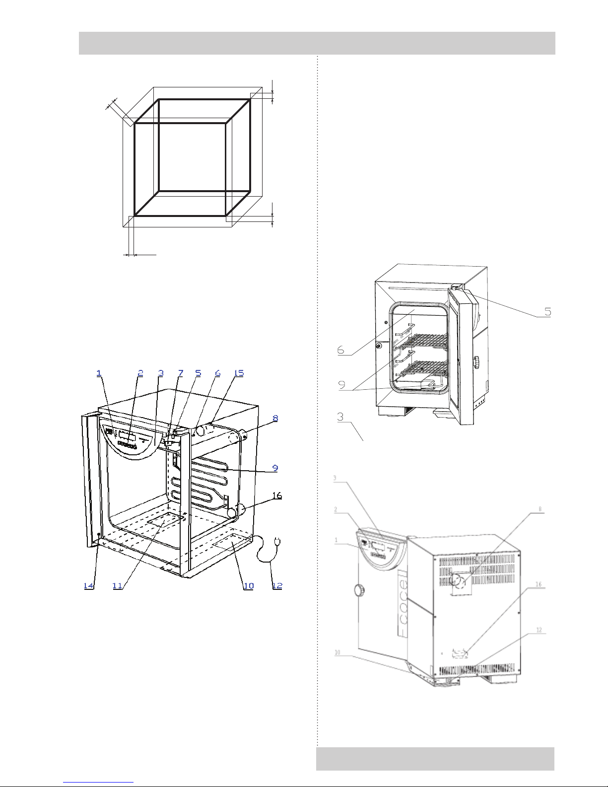
Fig. 1
3 description of the
oven
3.1
GENERAL VIEW
Fig. 2
1 - controller panel
2 - control keys
3 - plastic cover of the controller panel
4 - control ring and safety thermostat key
5 - lever for air ap positioning
6 - case of PT 100 sensor
7 - fan (only for VC, ICV)
8 - exhaust with air ap (with all types)
9 - heating elements
10 - power board I
11 - power board II (only three-phase type)
12 - mains cord
14 - door sensor (see chapter Optional
Accessories)
15 - suction hole (only for VC, ICV, with air ap)
16 - suction hole (with types EC, DC, IC).
ECOCELL 22
Instructions for use
LSI_K_np_en 1206_mmm_V2.08_B2V 5
X (H)
X (V)
2
X (V)
1
X (Š)
VENTICELL 22

1 Connector RS-232C (Canon) for printer
2 Supply lead
3 Screws attaching the power part
4 The power part panel (placed in foot)
9 pin Canon connector on the case
Pin Signal
2 RXD
3 TXD
5 GND
6 DSR
1
2
3
4 5
6
7
8 9
Fig. 6: 9 pin Canon - Interface for protocol printer
25 pin Canon connector on the printer
Pin Signal
2 TXD
3 RXD
7 GND
20 DTR
The appliances, which are connected with the
connector RS-232C, must comply with valid
regulations in terms of electric safety and
electromagnetic compatibility.
Interface parameters: Baud: 9600
Stopbit: 1
Parity: none
Databit: 8
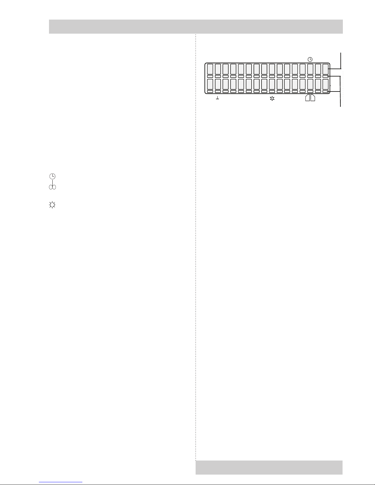
3.3
CONTROL PANEL
Fig. 5
1. key of activation of setting-up mode
2/4. cursor steering turning to the left/right
3. setting-up value in parameter
5. key starting the program
6. switch (ON - on, OFF - stand by)
Instructions for use
6 LSI_K_np_en 1206_mmm_V2.08_B2V
VENTICELL 22
3.2
POWER CONNETION AND CONNECTORS
1 2
3
4
Fig. 5 Foot of the unit with power supply - rear view
(with the power part I)
ON
OFF
X
W
START
STOP
RH
5 6
Program Segment
°C
*
1 2
3 4
5 6
7
8
9
10
11
12
13
Instructions for use
LSI_K_np_en 1206_mmm_V2.08_B2V 7
Positions
Návod k použití
Pozice na displeji:
Program: zobrazení programu
Segment: Dílčí nebo úplné gracké zobrazení
průběhu programu
°C: Zobrazení teploty
: Čas procesu
: Ukazatel rychlosti ventilátoru v %
(kroky po 10 %)
RH: relativní vlhkost v %
☼ Nastavení intenzity expozičního světla
ve dveřích
56 Pozice jsou použity pro specické účely
– viz popisy v textu.
4 FUNKCE A OBSLUHA
Funkce jednotlivých kontrolek a ovládacích
tlačítek je popsána v kapitole 3 - Popis přístroje,
a 3.4 - Ovládací panel.
Připojení k elektrorozvodné síti:
Hodnoty jmenovitého napětí a příkonu přístroje,
které jsou uvedeny na výrobním štítku,
porovnejte s přívodem napětí. Pokud parametry
přívodu odpovídají parametrům přístroje, zapojte
vidlici přístroje do zásuvky přívodu.
Zapnutí přístroje:
Stiskněte tlačítko
O
N
O
F
F
, (nad kterým se rozsvítí
kontrolka), displej se rozsvítí, tímto je přístroj
připraven k provozu, pokračujte podle bodů
uvedených níže.
Displej zobrazuje všechny parametry najednou.
Kurzor se pohybuje pod všemi 32 místy displej
v tzv. kurzorové lince a je vždy umístěn pouze
pod jedním z 32 znaků.
4.1 ZÁKLADNÍ NASTAVENÍ PŘÍSTROJŮ
Přístroje teplotní techniky s regulátorem Komfort
– nabízí zákazníkovi širokou škálu využití.
Základem pro správné spuštění systému je jeho
optimální počáteční nastavení. K tomu slouží
následující servisní režim obsahující 10 různých
služeb.
4.1.1 AKTIVACE SERVISNÍHO REŽIMU
Zmáčkněte současně tlačítka ▲► a držte je
po dobu 2 s. Na displeji se objeví informace
Service 01. Pomocí tlačítka ▲ můžete přepínat
mezi jednotlivými službami Service 01 – Service 07,
Service 41 a 59.
4.1.2 SERVICE 01 - ULOŽENÍ PROGRAMŮ
P1 - P4, NEBO P5, NEBO P6 NA
ČIPOVOU KARTU
Pomocí této služby můžete uložit programy P1 –
P4, nebo P5, nebo P6 na čipovou kartu výrobce
přístroje. Před vlastním zápisem parametrů na
čipovou kartu je nejdříve nutné vložit do štěrbiny
v panelu přístroje správnou kartu. Tyto karty je
možné přiobjednat u dodavatele přístroje.
Ujistěte se, že se čipová karta nachází ve
čtecím zařízení!
Uložení proveďte stiskem
X
W
. Správnost
uložení je potvrzena sdělením “Provedeno” na
displeji. Stiskněte podruhé START/STOP, tím
umožníte přechod do jiné služby.
Pokud je na displeji sdělení “Spatna MMM
CCard”, zkontrolujte čipovou kartu a činnost
opakujte.
Základní postup je následující:
Stiskem START/STOP nejdříve otevřete službu
ukládání programů.
K dispozici jsou možnosti P1 – P4, nebo P5,
nebo P6. Výběr proveďte pomocí ▲.
Vlastní uložení programu proveďte stisknutím
X
W
. (Detailně: Před spuštěním: na displeji je
nápis: „Servis 01““Zapis na kartu“
°c
Program Segment
RH
5
6
Pozice
1 2 3 4 5 6 7 8 9 10 11 12 13 14 15 16
Cursor line
(32 digits)
Parameter change:
Move the cursor horizontally by pressing ◄►.
Parameter below which there is the cursor can
be changed by means of button ▲.
4.1 bASIC SETTING OF THE UNITS
Thermal technology units with the Comfort
regulator offer a wide range of utilisation for the
customer. In order to make them active, there are
fundamental inputs required. To achieve this the
following service mode.
4.1.1 ACTIVATING THE SERVICE MODE
Press simultaneously buttons ▲► for 2 seconds.
The display displays the information Service 01.
You can change between individulal services by
means of button ▲.
4.1.2 SERVICE 01 – STORING P1- P
6
With help of this service you can store programs
P1 – P6 on the chip card. Before storing the
parameters to the chip card it necessary to insert
the right card to the unit panel. These cards can
be ordered optionally.
Make sure that the chip card is in the card
reader!
Press START/STOP to open the programme
saving service.
The display shows: „P1 ÷ 6 → MMM CCard”,
Press X/W to do storing. The transmission is
conrmed by the read out „Done“ on LCD. Press
START/STOP again to enter another service.If
the read out on the LCD is „Bad MMM CCard“,
check the chip card and repeat the procedure.
4.1.3 SERVICE 02 - RESTORE
/
UPLOAD THE
PROGRAMS FROM THE CHIP CARD
Using this service you can record programs
P1 - P6 previously stored on the chip card into
the memory of the unit again. The programs
entered into the memory before will be deleted.
7. indicator light - shines after switching on the
switch
8. indicator light heating - shines: state of
temperature regulator - heating active
9. indicator light cooling - shines: state of
temperature regulator - cooling active
10. indicator light – failure
11. indicator light of safety thermostat - shines:
temperature surpassed the limit set on
the safety thermostat - heating is off / see
paragraph 4.1.8 - Set safety thermostat
12. display
13. port for inserting the chip card.
Position on the display:
Program: displaying the program
Segment: partial or full graphic representation of
the program coarse
°C: temperature display
: process time
: fan speed display in % (steps of 10 %)
RH: % relative humidity
: setting-up intensity of exposition light in the
door
56 : positions are used for specic purposes -
see descriptions in text.
4
function and
operating
Function of the control lights is described
in section 3 - Description of the unit, in
paragraph 3.3 - Control panel.
Connecting to mains:
Compare the nominal voltage input values
indicated on the index plate with the supply
voltage. If the supply parameters correspond with
the unit parameters, connect the unit’s plug with
the supply socket.
Switching the device on:
Press the ON/OFF button. An indicator above
it lights up. The device is ready for operation,
follow the below given instructions.
The display displays all parameters together for
your information. The cursor moves below all
32 places along the so called cursor line and
it is located always below only one of the 32
characters.

8 LSI_K_np_en 1206_mmm_V2.08_B2V
Instructions for use
The programs in the memory will be recorded
over (erased). Make sure the chip card is in
the card reader. Press START/STOP to open
the programme download service. The display
shows: „MMM CCard → P1 ÷ 6”,
Press X/W to record. The transmission is
conrmed by the read out „Done“ on LCD. Press
START/STOP again to enter another service. If
the read out on the LCD is „Bad MMM CCard“,
check the chip card and repeat the procedure.
ATTENTION!
The original chip card delivered by the
manufacturer should be used only. Cards whose
type ends with the gure 1024 (AT24C1024) may
only be used. Older cards ending with the gure
16 may not be used.
4.1.4 SERVICE 03 - SET THE REAL TIME
AND DATE
Pressing START/STOP you enter the service.
Set the real time and date by pressing buttons
◄► and ▲. Enter the date format setting by
shifting the cursor behind the display edge,
using the buttons ◄►. The date format is
selected by pressing ▲ while the cursor is
on the position 7. The possible formats are
(in Czech): RRRR-MM-DD, RRRR-DD-MM,
MM-DD-RRRR, and DD-MM-RRRR. The default
format is RRRR-MM-DD. (In other languages:
YYYY-MM-DD, JJJJ-MM-TT, or AAAA-MM-JJ).
The data delimiter is selected by pressing ▲
while the cursor is on the position 6. The key ◄
takes you back to the time setting.
To quit the service press START/STOP again.
4.1.5 SERVICE 04 - SET INTERVAL
ON PRINTER/COMMUNICATION
INTERFACE
To print the protocols the units of thermal
technology may be provided (optional) with a
printer, which is connected by a cable to the
printer interface – see chapter 4.8 - Printing the
protocol by START/STOP and set the interval:
Pressing ▲ select one of the following choices:
- printer OFF
- switched over to PC (application of SW
WarmComm – data are sent to PC)
- interval 10 s
- interval 01 min
- interval 01 hr.
By pressing ◄ move the cursor to the position
10/01 seconds, minutes or hours. By pressing
▲ you can change the printer interval within the
following range:
-10 to 50 s (step 10 s)
- 01 to 59 min (step 1 min)
- 01 to 12 h (step 1 h).
One unit only is active, either seconds, or
minutes, or hours.
By further move of the cursor to the display edge,
you enter printer selection. Select the printer type
by means of ▲
Printer=1 ... Citizen
Printer=2 ... Thermal printer DPT 6333-V.24
To quit the service press START/STOP again.
4.1.6 SERVICE 05 - SELECT LANGUAGE
Pressing START/STOP you enter the service.
To select the language use button ▲ To quit the
service press START/STOP again.
4.1.7 SERVICE
06 –
SETTING THE
SWITCHING TIMES OF INNER SOCKET
(
OPTIONAL
)
AND THE FAN RUN AFTER
THE PROGRAMME TERMINATION
A) Switching times setting
ATTENTION!
Using this service you can set the time of
periodical switching on and off of the inner
socket.
Open the service by pressing START/STOP. The
bottom line of LCD states:
“on: XXPP off: YYQQ”,
where XXPP is the time for which the socket is
switched on for one part of the period (00 – 99),
YYQQ is the time when it is switched off (00 –
99).
PP is the abbreviation of time unit (minutes or
hours) for switching on, QQ for switching off.
The following applies: XXPP + YYQQ = whole
period.
Use ◄ and ► to move the cursor, use ▲ to
change the numbers of time units or units.
If XX = 00, then the socket never switches
on, if XX ≠ 00 and YY = 00, then the socket is
permanently switched on after the start up to
termination.
B) Setting the fan run after the programme
termination
Leave the “inner socket” setting by means of
◄► and by pressing ▲, set:
a) “Prog” – the fan runs only during the P1-P6
run;
b) „T50C“-„T250“ – the fan runs even after
program termination, up to temperature
decrease below pre-set value (it is possible

to set the value from 50 °C to 250 °C in 10 °C
increments),
c) “Door” - the fan keeps running after the
programme termination and switches off after
the door opening (applied only for units with a
closed door sensor);
d) “alws” – the fan keeps running till the cabinet is
switched off by the ON/OFF button.
Other options are available to VH only:
e) “Off“ – fan switched off,
f) „End“ – the fan starts after program termination
and switches off only when the device
is switched of. In the course of program
operation the fan stops, which positively
affects the thermo homogeneity.
4.1.8 SERVICE
07
- SAFETY THERMOSTAT
SETTING
Safety thermostat serves to protect the
thermal technology cabinet, its surrounding
and treated material against inadmissible rise
of set temperature (e.g. prevents damage
or destruction of material samples in case of
damage to the temperature regulator or in case
of unintentional setting of a temperature in the
chamber of the unit higher than the sample is
able to withstand).The service is opened by the
depression of the START/STOP button.
Set the upper limiting temperature selected
by you on the bottom line of the display – on
the position 12, 13, and 4 (symbols XXX on the
display). The minimum difference from the preset
regulated temperature is +5°C. Set the safety
thermostat type on the position 16 (symbol Y on
the display):
Type 2 – It is used for the types VC, EC, and
DC. If the preset temperature in the chamber
is exceeded, the display shows the error 04
– “Therm.protect.activated”. The thermostat
switches off the heating elements; the indicator
“safety thermostat” and the acoustic alarm are
switched on. The unit does not heat although the
indicator “heating” shines.
To restart the activity, the safety thermostat must
be reset – the error message and the acoustic
alarm are cancelled by pressing the button
START/STOP. The safety thermostat is also reset
after each pressing the button X/W in the service
07.
Type 3 – It is used for the IC and ICV types. If the
preset temperature in the chamber is exceeded,
the thermostat switches off the heating elements;
the indicator “safety thermostat” and the acoustic
alarm are switched on and the display shows the
alternating messages “Therm.protect.activated”
and the previous information. The unit does not
heat although the indicator “heating” shines.
After the temperature in the chamber drops
below the preset limit of the safety thermostat,
the unit continues its work (e.g. the heating
is switched on again) – the indicator “safety
thermostat” turns off. The acoustic alarm is still
active and the display shows the alternating
messages “Ochr.term.aktiv” and the previous
information. Cancel these two non-standard
status signals by pressing the button START/
STOP.
To conrm set temperature and type of the
thermostat, insert the chip card „SO“ in the card
reader and press X/W.
Terminate the service and close by the
depression of START/STOP button again.
Check of the safety thermostat function:
According to the procedure described in Service
07 – setting the safety thermostat - set the
temperature limit to 85 °C and conrm with the
chip card SO. In P1 set the temperature 60 °C
and start the program. After reaching the set
temperature wait for about 10 minutes, stop the
program and select the Service 07; in Service
07 - set the temperature limit to 50 °C and
conrm with the chip card SO. The unit operates
according to the description in Service 07
– Setting the safety thermostat: report ”Safety
Thermost.” on the display etc.
4.1.9 SERVICE
41
- TEMPERATURE
TOLERANCE
The bottom line of the display shows the
message “+XX.X °C -YY.Y °C”, where “+XX.X”
means the upper deviation of the temperature
(adjustable range 0 to +20) and “-YY.Y”
means the lower deviation of the temperature
(adjustable range 0 to -20). If a situation occurs
during the programme run that the temperature
in the chamber is lower than the preset
temperature minus the lower deviation,
error 2 is shown. If a situation occurs during
the programme run that the temperature in the
chamber is higher than the preset temperature
plus the upper deviation, error 3 is shown. If
a 00.0 deviation is set, the deviation is not
controlled.
The type of the errors no. 2 and 3 when the
temperature goes out of the preset range is
selected on the last character. There are the
possibilities “H” (the errors are “critical”) –
the programme run is stopped; or “S” (the errors
are “soft”) – the programme keeps running. The
default value (after RAM initialization) is “H”
(critical error).
LSI_K_np_en 1206_mmm_V2.08_B2V 9
Instructions for use

4.1.10 SERVICE 58 - DOOR bLOCKING
This service is available only in models equipped
with the door blocking function.
One-door model:
Press START/STOP and open the service.
Select one of the following possibilities by means
of ▲:
1. Inactive – the door is unblocked permanently
2. Manual – the door can be blocked and
unblocked by means of ▲ and ►
3. Automatic – the door is blocked automatically
after a pre-set period of time elapses after the
door closing.
The time can be set within the range from 2 to 9
seconds. Unblock the door by pressing ▲ and ►
buttons for 2 seconds.
You can select “C” on the last display position. In
such case, the door can be unblocked only after
inserting the SO card.
S e r v i c e 5 8
A u t o m . a f t e r 2 s C
Two-door VENTICELL models:
After the service is started, the cursor is placed
on the rst left position; four statuses can be preset on the bottom line by means of ▲:
S t r : A
=
O p n B
=
L c k
This status denes the door blocking after the
programme start by means of START/STOP.
S t p : A
=
O p n B
=
L c k
This status denes the door blocking after the
programme interruption by means of START/
STOP.
E n d : A
=
L c k B
=
O p n
This status denes the door blocking after the
programme termination (the panels show “Konec
Px” and “End”.
U n l o c k a l l ( X / W )
Press X/W to unblock both doors.
Use ◄ and ► to move the cursor between “A” =
loading door, and “B” = unloading door.
Three values are dened for these options (the
tables show the initial setting):
• „Opn“ – unblocked
• „Lck“ – blocked
• „Txyz“ – the door will be unblocked after the
temperature in the chamber drops below
“xyz”. “xyz” can be pre-set by means of ▲ in
the range from 50 to 200 °C.
It is recommended to pre-set the same “xyz”
value as in Service 06 (duration of the ventilator
run after the programme termination).
“A=Lck” cannot be pre-set if the device is in “Stp”
status. “A=Lck” only can be pre-set if the device
is in “End” status.
The device will be in “Stp” status only if the
programme run is interrupted by means of
START/STOP; however, this shall not be applied
if an error status is cancelled by means of
the said button. The door blocking will remain
unchanged after the error status cancellation.
See more in the Chapter Optional Accessories.
4.1.11 SERVICE
62 –
SOUNDS SETTING
This service allows individual switch-on and -off
of the following events:
- Device switch-on;
- Device errors;
- Operator’s errors;
- Buttons pressing;
- Programme start;
- Programme end;
- Door opening during the programme run.
4.1.12 SERVICE
64 –
PROGRAMME P
6
SHIFTING
This service shifts the programme start to a new
time. See more in chapter Programme P6.
4.1.13 SERVICE
09 -
CANCEL THE SERVICE
MODE
By pressing START/STOP, the service mode is
cancelled. You can then modify programmes and
start them freely.
4.2 PROGRAM P
1
Constant temperature is required.
P 1 =
The cabinet operates continuously at set
temperature until switching the unit off.
4.2.1 SET P
1
Put cursor to the position Program with help of
◄► and switch to P1 with help of ▲. Set the
temperature at the position of °C within the range
10 LSI_K_np_en 1206_mmm_V2.08_B2V
Instructions for use

of the type of the unit - see item Purpose and use
– with VC, EC, DC cabinets it is possible to set
in 1 °C steps, with IC and ICV in 0.1 °C steps.
Set the fan speed (type VC ICV) at the position
from 10, 20....up to 100 % (these are the
percentages of maximum speed).
ATTENTION!
Do not reduce the fan speed if it is not
necessarily needed. Reduced fan speed may
cause reduced accuracy!
4.2.2 LCD - READ OUT SHOWN
°c
Program Segment
RH
5
6
P /1
1
0 0
0 0
. 0 0 0 : 0 0
–
–
– – – –
4.2.3 START P
1
Press START/STOP, a sound will appear and the
“windmill“ in the rst digit of LCD starts running
clockwise.
See the following LCD read out:
°c
Program Segment
RH
5
6
*
/1
1
°C °C °C
0 0
.
h h
m m
:
–
Digit 1 (windmill running) = program running
Digit 7 to 10 = actual temperature in °C.
Digit 12 to 16 = time from the start in hr:min.
As soon as the set values are reached, then run
down time is shown.
4.2.4 INFORMATION ON THE SET
PARAMETERS DURING RUNNING
Press X/W and all information on the set
parameters are shown at once. All possible
parameters in all possible programs can be set
including the one which is presently active, as
long as the change is effective.
4.2.5 STOP P
1
Press START/STOP again.
4.3 PROGRAM P
2
SETUP-temperature is reached rst, dened
time will run down and when nished the heating
is turned off.
P 2 =
The unit operates at set temperature until the
lapse of set time (max. 99 hr 59 min).
4.3.1 SET P
2
With help of buttons ◄► put the cursor to the
position Program and switch to the program P2.
Set the temperature at the position of °C.
Move the cursor to the position
¹ and set the
run down time between 00hr:00min to 9999 hr,
at the position
(type VC, ICV) change the fan
speed between 10, 20...100 %.
ATTENTION!
Do not reduce the fan speed if it is not
necessarily needed. Reduced fan speed may
cause reduced accuracy!
4.3.2 LCD - READ OUT SHOWN
°c
Program Segment
RH
5
6
P /
/
2
1
0 0
0 0
. 0 0 0 : 0 0
–
–
–
–– –
4.3.3 START P
2
Press START/STOP, a sound will appear and
the “windmill“ in the rst digit of LCD starts
running clockwise.
See the following LCD read out:
°c
Program Segment
RH
5
6
*
/
/
2
1
°C °C °C
0 0
.
h h
m m
:
–
°C°C°C = actual temperature
hh:mm = time to reach the set temperature, if
the set-up is reached, the rest of the run down
time is indicated.
After the programme ends, temperature in the
chamber and the text “End” are displayed.
LSI_K_np_en 1206_mmm_V2.08_B2V 11
Instructions for use

Programme end indication and temperature in
the chamber disappear after pressing any panel
key.
4.3.4 INFORMATION ON THE SET
PARAMETERS DURING OPERATION
OF THE UNIT
See item 4.2.4.
4.3.5 STOP P
2
Press START/STOP.
4.4 PROGRAM P
3
Delayed start begins after given time.
[The function starts for example at the weekend.
Thus your goods are ready on the rst day of
return to work.]
P 3 =
Starts running after the delayed time has run
down (max. 9999 hr) and the unit operates at
the set temperature. The duration of the set
temperature can be limited or unlimited in time.
4.4.1 SET P
3
By pressing ◄► put the cursor to the Program
position and switch to P3. By pressing ◄► put
the cursor to the graph and make sure that the
segment 1 in the graph is activated (otherwise
change by buttons ▲.
Set the time of delay between 00hr:00min to
9999 hr position
¹. By pressing ◄► move
to the graph and with help of ▲ change to the
segment 2 in the graph _/¯. Set the temperature
in elds °C.
Move the cursor to position
¹ and set the time
of process duration between 00 hr:00 min. up
to 9999 hr. or unlimited ∞∞:∞∞ (set the innity in
the following way: set 9999 hr, put the cursor to
the nine in units and depress ▲. Set the cursor
(with types VC, ICV to position
and set the
fan speed between 10 up to 100 %.
ATTENTION!
Do not reduce the fan speed if it is not
necessarily needed. Reduced fan speed may
cause reduced accuracy!
4.4.2 LCD - READ OUT SHOWN
4.4.3 START P
3
Press START/STOP, a sound will appear and the
“windmill“ in the rst digit of LCD starts running
clockwise. See the following LCD read out:
4.4.3.1
P3 AND SEGMENT 1 IN THE GRAPH
ARE ACTIVE
°c
Program Segment
RH
5
6
*
/3
1
°C °C °C
0 0
.
h h
m
m
:
–
–
–
= první segment
°C°C°C = actual temperature
hh:mm = the programmed time, counting ⇒
down towards zero.
4.4.3.2 P
3
AND SEGMENT 2 IN THE ARE
ACTIVE, THE SEGMENT
1
IS OVER
°C°C°C = actual temperature
hh:mm = time running from the start till the set
temperature has been reached.
After the set temperature has been reached,
the run down time is shown if the time of the
procedure is unlimited. If the time is limited, the
rest of the run down time is shown.
12 LSI_K_np_en 1206_mmm_V2.08_B2V
Instructions for use
segment 1
Program Segment
°C
RH
5 6
*
3
//
–
°C
°C
°C
.
1
0
0
h
h :
min
=
=
//
–
= druhý segment
segment 2
°c
Program Segment
RH
5
6
P /3
1
0 0
0 0
. 0 0 0 : 0 0
–
–
–
–
––
–– – –

r = ramp value, can be set on digits 12 – 16 and
corresponds with temperature change speed
in °C/min max. value is +3.2 °C/min, when
T0 < T1, or T1 > T2 If r = 00.0, no ramp
active! (The numerical value of the ramp has
an orientation character, the real speed can
be affected by the amount of goods in the
chamber and maximum speed of temperature
change may not be met, taking the limited
heating power into account)
t = time available in position
¹ (00hr:00min –
9999 hr), at T2 the dwell time can be
unlimited
c = cycles shown in position ¹, digits 12 – 13 on
LCD (available only at T2, if the dwell time is
unlimited) Possible number of cycles is 2 to
9999 (eventually ∞- which is the next position
after 99).
The value of cycle number is a global value that
does not relate to individual segments, it relates
to the complete programmed sequence. It can
be displayed while displaying any segment on
the display, however it does not concern only
the displayed segment, but the whole sequence!
Minimum number of cycles is 1. If only one cycle
is chosen, the programme runs as if it has been
switched on without cycles.
The program can be started by depressing
START; no matter which segment is shown on
the display, the program always runs from the
segment 0 or 1, if the time of the zero segment
is zero. For successful inserting of the cycling
process into an already started process it is
essential that at the moment of the start “cXX” is
shown on the display, where XX is the number
of intended runs of the whole sequence. E.g.
number two means, that the sequence is carried
out and then repeated completely, i.e. it runs
twice around. If “cXX” is not shown on the display
at the moment of the START and there is shown
data on time or on the ramp of the actually
displayed program instead, the whole sequence
runs once and is not repeated, i.e. there are no
cycles.
4.5.2 SET THE SEGMENT FOR T
1
4.5.2.1 SET TEMPERATURE T
1
Put cursor to the position Program and switch
to P4. By pressing ◄► place the cursor on the
graph and make sure that T1 (/¯\_) is activated. If
not, activate it with buttons ▲.
Change to the position of °C - temperature setting
- and set the temperature.
4.4.3.3 P3 AND THIRD SEGMENT IN THE
GRAPH ARE ACTIVE
The preset temperature has been reached. If the
procedure duration is unlimited, time passed is
displayed. If the procedure duration is limited,
time remaining till the end is displayed. After the
programme ends, temperature in the chamber
and the text “End” are displayed. Programme
end indication and temperature in the chamber
disappear after pressing any panel key.
4.4.4 INFORMATION ON THE SET
PARAMETERS DURING OPERATION OF
THE UNIT
See item 4.2.4.
4.4.5 STOP P
3
Press START/STOP.
4.5 PROGRAM P
4
With 2 temperature levels T1 and T2, with a
controlled speed of the temperature change
(ramps) and with cycling.
P4 =
T1 T2
Operates at 2 temperature levels T1 and T2, the
dwell time on the level T1 is limited, on the level
T2 can be limited or unlimited.
4.5.1 SET P
4
Index: T0 = initial chamber temperature
T1 = temperature level 1
T2 = temperature level 2
Digit 11 on LCD = (placed between temperature
and dwell time values), shows the following
information:
LSI_K_np_en 1206_mmm_V2.08_B2V 13
Instructions for use
Program Segment
°C
RH
5 6
*
3
//
–
°C
°C
°C
.
1
0
0
h
h :
min
=
=
/
–
= druhý segment
segment 3

4.5.3 SET THE SEGMENT FOR T
2
4.5.3.1 SET THE TEMPERATURE T
2
Place the cursor on the graph and make sure
that T2 ( /¯\_ ) is activated. If not, activate
with help of ▲. Switch over to position °C -
temperature setting - and set the temperature.
4.5.3.2 SET THE DWELL TIME OF T
2
Put the cursor on the digit 11 on LCD and ask
for parameters by pressing ▲. Either „t“ or „r“ or
„c“ will appear. Select „t“. Enter the position
¹
and set the dwell time between 00hr:00min and
9999 hr, unlimited ∞∞:∞∞ (set the innity in the
following way: set 9999 hr, put the cursor to the
nine in units and depress▲.
4.5.3.3 READ OUT OF T2 AND THE DWELL
TIME
°c
Program Segment
RH
5
6
P /
/
4
1
0 0
0 0
. 0 0 . 0 0
–
–
–
r
+/-
4.5.3.4 SET THE RAMP AT T
2
Return the cursor to the digit 11 on LCD and by
pressing buttons ▲ select „r“. Switch to position
¹ and set the required ramp (max. value
+3.2 °C/min for T1 < T2). If the ramp is not
needed, leave „r“ on 0.00. In this case the
temperature will be changed at maximum
speed. The symbol ± appears automatically
in accordance to T1 and T2 relation (see item
4.5.2.4.).
4.5.3.5 READ OUT OF T2 AND THE RAMP
°c
Program Segment
RH
5
6
P /
/
4
1
0 0
0 0
. 0 0 . 0 0
–
–
–
r
+/-
4.5.2.2 SET THE DWELL TIME OF T
1
Move cursor to the digit 11 on LCD and ask for
parameters by pressing simultaneously ▲ Either
„r“ or „t“ will appear (see above). Select „t“. Move
to the position
¹ and set the dwell time between
00 hr:00 min and 9999 hr.
4.5.2.3 READ OUT OF T
1
AND THE DWELL
TIME
°c
Program Segment
RH
5
6
P /
/
4
1
0 0
0 0
. 0 0 0 : 0 0
–
–
–
–
–
–
–
– –– – –
t
4.5.2.4 SET THE RAMP AT T
1
Return the cursor to the digit 11 on LCD and by
pressing ▲ select „r“.
Switch to the position
¹ and set the required
ramp (max. value +3.20 °C/min for T0 < T1).
If the ramp is not needed, leave „r“ on 0.00.
In this case the temperature will be changed
at maximum speed. The symbol ± appears
automatically in accordance to T0 and T1 relation
(the ramp with negative value of temperature
change speed may be set in case that the speed
of spontaneous cooling of the cabinet is higher).
4.5.2.5 READ OUT OF T1 AND THE RAMP
°c
Program Segment
RH
5
6
P /
/
4
1
0 0
0 0
. 0 0 . 0 0
–
–
–
r
+/-
4.5.2.6 SET THE FAN SPEED AT THE
TEMPERATURE T1
Put the cursor to the position and change the
fan speed between 10, 20...100 %.
ATTENTION!
Do not reduce the fan speed if it is not
necessarily needed. Reduced fan speed may
cause reduced accuracy!
14 LSI_K_np_en 1206_mmm_V2.08_B2V
Instructions for use

LSI_K_np_en 1206_mmm_V2.08_B2V 15
4.5.3.6 SET CYCLES FOR P
4
Return the cursor to the digit 11 on LCD and with
▲ select „c“. Switch to the position
¹, set the
number of cycles between 02 and 99 (eventually
∞). The number of cycles means, how many
times will the cycle run, i.e. value 03 means,
that at the end of the rst cycle will be the whole
process still twice repeated. Cycles are not
applied in case when the display does not display
„c“ in the moment of program start and after the
exposure termination at T2 drop of temperature
in the cabinet below the level of T1 must take
place.
4.5.3.7 READ OUT OF CYCLES FOR P
4
°c
Program Segment
RH
5
6
P /
/
4
1
0 0
0 0
. 0 10
–
–
–
c
4.5.3.8 SET THE FAN SPEED AT T
2
Put the cursor to the position and change the
fan speed between 10 to 100 %.
ATTENTION!
Do not reduce the fan speed if it is not
necessarily needed. Reduced fan speed may
cause reduced accuracy!
4.5.4 START P
4
ATTENTION!
If cycling is required, „c“ must be on LCD when
starting the program.
Press START/STOP, a sound will appear and the
“windmill“ in the rst digit of LCD starts running
clockwise. See the following LCD read out:
The graph shows the actual state of the program.
4.5.4.1 S1 IS ACTIVE, TEMPERATURE IS
HEADING TOWARDS T
1
°c
Program Segment
RH
5
6
*
/
/
4
1
°C °C °C
0 0
.
h h
m
m
:
–
–
= S1
°C°C°C = actual temperature
hh:mm = time since start to reaching T1.
4.5.4.2 S2 IS ACTIVE, T1 HAS bEEN
REACHED, DWELL TIME IS RUNNING
°c
Program Segment
RH
5
6
*
/
/
4
1
°C °C °C
0 0
.
h h
m
m
:
–
–
–
= S2/T2
°C°C°C = actual temperature
hr:mm = dwell time at T1 running down
towards zero.
4.5.4.3 S3 IS ACTIVE, TEMPERATURE IS
HEADING TOWARDS T
2
°c
Program Segment
RH
5
6
*
/
/
4
1
°C °C °C
0 0
.
h h
m
m
:
–
–
= S3
°C°C°C = actual temperature
hr:min = time running since the end of T1 till it
reaches T2.
Instructions for use
P4 =
S1 S2 S3 S4
T1 T2

4.5.4.4 S4 IS ACTIVE, T2 IS REACHED, DWELL
TIME AT T
2
IS RUNNING
°c
Program Segment
RH
5
6
*
/
/
4
1
°C °C °C
0 0
.
h h
m
m
:
–
–
–
= S4/T2
°C°C°C = actual temperature
hr:mm = in case the time of the procedure is
unlimited the time of running is shown, in case of
the limited time the rest of this time is shown.
4.5.5 INFORMATION ON SET PARAMETERS
DURING OPERATION OF THE UNIT
See item 4.2.4.
4.5.6 STOP P
4
Press START/STOP.
4.6 PROGRAM P
5
4.6.1 DESCRIPTION OF P5 AND ITS
CONTROL
T
tn=max 15
t7t6t5t4t3t2t1t0
T7
T4
T3
T5 T6
T1 T2
S0
S1
S2
S3
S4
S5
S6
S7
Sn
t
tn=max. 39
The program consists of 40 segments. Segment
0 is for the delayed start, it is dened only by
the time t0. If t0 is 0, there is no delayed start.
Segments 1 to 39 are of the same qualities, each
of them is dened only by the end temperature,
time or speed (ramp), fan rotation speed and
depending on the type of the unit also by relative
humidity and chamber light.
Each of the segments 1 to 39 can be set as
the last and innite, that is the program at this
segment must be nished by START/STOP
button.
Instructions for use
16 LSI_K_np_en 1206_mmm_V2.08_B2V
If the cycle selection is active on LCD at the
moment of the start, see g. Display - state of the
program selection - E: cXX, the program comes
again to the start after the last segment is over
and the whole program is repeated. The denite
number of program cycles corresponds with the
number behind the letter “c“. The segment 0 can
be counted into the cycle as well even when it is
zero.
Range of parameters:
time t0 0 hr, 0 min to 9999 hr
time t1 to t39 0 hr, 0 min. to 9999 hr, or
innite ramp
Rampe r1 to r39 to 3.2 °C/min for heating
(negative sign for an
eventual cooling down)
temperature T1 toT39 range according to the
device parameters
fan speed V1 to V39 10 to 100 % with 10 % steps
number of
cycles
C 2 to 99 eventually ∞- which
is the next position after 99
DISPLAY - STATE OF THE PROGRAM SELECTION
A
B C D E
G H IF
A: P5 name of the program
B: XX number of the set segment
C: X type of the set segment:
x time of the zero segment is set to zero,
segment will be skipped over
> not the last, the end length - see E
>I the last, the end length - see E
∞ the last, innite length
D: XX . X required temperature of the set segment
(! the end temp.)
E: TXX : XX Hour and minute of the end of the set
segment; or
R ± X .XX The ramp = the required speed of the set
segment;deciding is the time; or
t ± X . XX The calculated hour and minute of the
end of the set segment; ramp is default;
or
r ± X .XX The calculated speed of the set segment;
time is default; or
cXX the number of cycles of the whole
program
F: XXX the fan speed of the set segment
G: XX the relative humidity of the set segment

device continues automatically from the point
before interruption.
4) If the device is switched off by the button
START/STOP or ON/OFF, the programme
starts running from the beginning after
reswitching-on.
Ventilator operation after a programme end:
The operation can be set in Service 06.
Immediate ventilator switch-off after programme
termination is pre-set in all ventilator types.
4.7 PROGRAM P
6
4.7.1 DESCRIPTION OF P
6
Programme P6 works with segments whose
duration is determined by real time and calendar
date.
1. Programme P6 consists of 40 segments
and is determined strictly by real time, i.e. it
follows the preset programme independently
of the switch-on time, power failures, restarts
after an error, etc.
2. Segment 0 (so called “delayed start”) is
compulsory; time and date must be set in it.
It may even be set to the past and means the
“beginning of the programme”. Segments 1 to
39 have the same properties. Each of them
is determined by the end temperature, time
or speed of temperature rise, and ventilator
speed.
3. If cycling is switched on, segment end times
are shifted after each cycle end (forward
by the programme duration). Updated
parameters are thus displayed when you
check the parameters during the device
operation (after X/W pressing).
4. The whole P6 programme (all segments at
once) can be shifted by service 64 by any
time interval to both the future and past and
there is no need to rewrite all segments
before a new programme start.
H: XXX the light of the set segment
I: XX . XX the month and day at the moment (at P5
impossible to be set )
DISPLAY - RUNNING OF THE PROGRAM
A
B C D E
G HF
A: ∗ 5
the rotating symbol and the program
number
B: X the number of the relevant segment
C: X the type of the set segment:
> not the last, the end length - see E
>Ι I the last, the end length - see E
∞ the last, innite length
D: XX . X the temperature in the chamber at the
moment
E: XX : XX the segment time at the moment -
hours, minutes
all segments - counting down from the
set value towards zero,
in case of an innite length of the last
segment counting up from zero
in case the time is higher than 9999 hr.
>>:>> is indicated
F: XXX the fan speed at the moment
G: XX not used
H: XXX not used
Programme P5 continuation after preset
parameters change or programme interruption:
1) The programme is running e.g. in segment 5.
You want to change the setting in a passed
already segment (e.g. segment 4) or in a
future segment (e.g. segment 6). Press
X/W and change the setting according to
your needs. Meanwhile, the programme
will continue running in segment 5. Wait for
several second. The programme returns from
the setting mode to the working segment 5
and continues working.
2) The programme is running e.g. in segment 5.
You want to change the setting of the running
programme 5. Press X/W and change the
programme 5 setting according to your needs.
Wait for several seconds. The programme
returns from the setting mode to the beginning
of segment 5 and starts running.
3) The programme is running. Power supply is
interrupted either by switching the main device
switch off or due to power supply system
failure. After the power supply is renewed, the
LSI_K_np_en 1206_mmm_V2.08_B2V 17
Instructions for use
T
tn=max 15
t7t6t5t4t3t2t1t0
T7
T4
T3
T5 T6
T1 T2
S0
S1
S2
S3
S4
S5
S6
S7
Sn
t
tn=max. 39

4.7.2 PROGRAMME SETTING
Segment 0 is compulsory, i.e. it cannot be
switched off. This condition must be met to
allow denition of the beginning, thus the whole
programme duration, which is necessary for
cycling.
When setting the delayed start, year is set on the
bottom line. Programme start can thus be preset
even to the past. Year will always be displayed at
the same place (7th position on the bottom line);
the sequence month-day (DD-MM or MM-DD) is
determined by setting in service 3.
P 6 0 0
>
2 2 . 5 0 9 : 0 0
1 0 0 2 0 0 9 1 8 - 0 2
or
P 6 0 0
>
2 2 . 5 0 9 : 0 0
1 0 0 2 0 0 9 0 2 - 1 8
In other segments, year is not displayed on
the bottom line; years are calculated at the
programme start.
Each of segments S 1 to S 39 may be set as the
last one, i.e. the programme either ends after the
nal temperature Ti reaching and concurrent time
ti elapsing, or another cycle may follow.
Each of segments 1 to 39 may be set as the
last one and innite, i.e. the programme must
be ended by means of START/STOP in this
segment.
If there is an active cycle selection displayed in
the moment of programme start (see the gure
Display – programme selection status – E: cXX),
then the programme passes to the beginning
again after the last segment ending and the
whole programme is repeated. The overall
number of the whole cycle runs equals to the
gure following the letter “c”. Segment 0 is not
included in the cycle.
The number of cycles is related to the whole
programmed sequence. It can be displayed in
presence of any segment on the display but it
does not refer to the displayed segment only but
to the whole sequence!
The minimum number of cycles is 1. If only one
cycle is selected, the programme runs as if it was
started without cycles. The programme can be
switched by the START button. Regardless of
the segment displayed actually, the procedure
starts from that segment which corresponds to
the moment of switching-on. However, to ensure
successful cycling inclusion in an already started
process, the display must show “c XX” in the
moment of the programmed sequence start; XX
is the number of the wanted whole sequence
runs. For example, number “two” means that the
sequence runs through and then it is repeated
once more. If no “c XX” but time or temperature
increase data of the actually displayed segment
are displayed in the moment of start up by means
of the START button, the whole sequence will
run through once only.
Time is indicated as a segment duration but is
dened by an hour, minute, day and month of its
end, i.e. real time. If the preset segment time and
date precede the preceding segment time and
date, the segment will end no sooner than in the
next year.
The actual time and date must be preset in the
system (regulator) in the service mode.
Range of parameters:
time t0 to t39 each of segments up to a
year
ramp r1 to r39 0 to 3.2 °C/min for heating,
–1.0 to 0 °C/min for cooling
temperature T1 to T39 0,0 - 99,9 °C
fan speed V1 to V39 10 to 100 % with 10 % steps
number of
cycles
C 2 to 99 (eventually ∞- which
is the next position after 99]
DISPLAY - STATE OF THE PROGRAM SELECTION
A
B C D E
G H IF
A: P6 name of the program
B: XX number of the set segment
C: X Type of the set segment:
> not the last, the end length - see E, I
>I the last, the end length - see E, I
ο the last, innite length
D: XX . X the required temperature of the set
segment (! the end temp.)
E: TXX : XX the hour and minute of the set segment
end, deciding is the ramp or
R ± X .XX the hour and minute of the set segment
end, deciding is the time or
tX ± XX The calculated hour and minute of the
end of the set segment; ramp is default;
or
r ± X .XX The calculated speed of the set segment;
time is default; or
cXX the number of cycles of the whole
program
F: XXX the number of cycles of the whole
program
Instructions for use
18 LSI_K_np_en 1206_mmm_V2.08_B2V

4.7.3 PROGRAMME START
After the programme is started (by means of the
START/STOP button or instruction from WC3),
years of the remaining segments are calculated
and the last segment time test is performed.
Three situations may appear:
1. The actual time is lower than the zero segment
time – waiting phase is started; the whole
programme will run through;
2. The actual time is higher than the zero
segment time but lower than the last segment
time – all segments that should have been
ended in the given time are skipped and that
segment whose time corresponds to the actual
one is started. Duration of such segment is
adapted so that it ended in the preset time
(shortened). LCD displays the time remaining
till the segment end.
3. The actual time is higher than the last segment
time – you can hear a warning audio signal
(“Operator’s error”) and the programme is not
switched on.
4.7.4 POWER SUPPLY FAILURE
The following situations may occur after a power
supply failure:
1. Programme without cycles, the actual time is
lower than the last segment time - segments
that should have been ended are skipped.
Duration of the “actual” segment is adapted
(shortened).
2. Programme without cycles, the actual time is
higher than the last segment time program
– the programme is ended (all segments are
“skipped” because the programme “ended”
during the power supply failure). LCD displays
“End”.
3. Programme with cycles, the actual time is
lower than the last segment time – see point
1 of this Article: Shortened “actual” segment
continues; the next cycle runs normally.
4. Programme with cycles, the actual time
is higher than the last segment time – the
programme denition is shifted by the
appropriate number of programme P6
durations so that the programme could
continue. Subsequent activity corresponds to
point 3 above.
4.7.5 AUTOMATIC SHIFTING OF P
6
PROGRAMME DURING CYCLING
After each cycle is ended, the programme
denition is recalculated (all segments are shifted
forwards by the programme duration). When
checking parameters during the programme
Instructions for use
LSI_K_np_en 1206_mmm_V2.08_B2V 19
G: XX not used
H: XXX not used
I: XX . XX month and day of the set segment end
DISPLAY - LAUF DES PROGRAMMS
A
B C D E
G HF
A: ∗ 6
the rotating symbol and the program
number
B: X the number of the relevant segment
C: X the type of the set segment
> not the last, the end length - see E
>| the last, the end length - see E
ο the last, innite length
D: XX . X the temperature in the chamber at the
moment (°C)
E: XX : XX the segment time at the moment - hours,
minutes
all segments - counting down from the
maximum value towards zero,
in case of an innite length of the last
segment counting up from zero
in case the time is higher than 9999 hr.
>>:>> is indicated
F: XXX the fan speed at the moment (%)
G: XX not used
H: XXX not used
ATTENTION!
When setting the time and temperature
parameters in the program 6 it is suitable to
follow the following principles:
If you need to change temperature in an already
preset chain of segments, notice whether the
nature (either rising or decreasing) or potential
subsequent or preceding temperature change
(indicated “R” or “t”) is in accord with the
expected change. If not, cancel the preset
temperature change and set it again only after
temperature setting.
At rst the temperature is set then the ramp. If the
ramp is deciding for the segment (“R“ or “t”), it is
suitable, if we want to change the temperature, to
switch over to time at rst (”T” or “r”).
When setting a chain of segments it is suitable
to go in the direction from the lower to the higher
segment.

run (by means of X/W button pressing), the
actual P6 setting can be viewed. After the last
cycle or programme without cycling are ended,
the parameters are not shifted, i.e. the last
parameters according to which the programme
ran can always be seen after the programme
ending or interruption (with or without cycles).
4.7.6 MANUAL SHIFTING OF P
6
PROGRAMME bEGINNING – USER
SERVICE
64
Duration of all segments remains unchanged.
S e r v
ι
c e 6 4
S h i f t p r o g r . P 6
After starting (START/STOP – see ), zero
segment time and date is displayed.
S e r v
ι
c e 6 4
0 9 : 0 0 2 0 0 9 - 0 2 - 1 8
or
S e r v
ι
c e 6 4
0 9 : 0 0 2 0 0 9 - 1 8 - 0 2
or
S e r v
ι
c e 6 4
0 9 : 0 0 0 2 - 1 8 - 2 0 0 9
or
S e r v
ι
c e 6 4
0 9 : 0 0 1 8 - 0 2 - 2 0 0 9
Any parameter can be changed (year can be
changed by one year forward or backward only
as compared to the actual year). By pressing
X/W, the programme is shifted by a difference
between the new and old segment time
(“Performed” is displayed).
S e r v
ι
c e 6 4
x
P e r f o r m e d
The programme can be shifted both forward
and backward. Time (hh:mm) is always at the
beginning of the line. Date is displayed in a
format selected in the user service 3 (i.e. 4
possibilities of the sequence year-month-day).
This differs from segment 0 setting, where year is
always in the rst place.
4.7.7 ExAMPLES OF P6 PROGRAMME
SETTING
Example 1: Day and night phase with different
temperatures
Required : 9.00 am – 5.00 pm – temperature
220 °C,
6.00 pm – 8.00 am on the next day – temperature
150°C, indenite number of cycles
P 6 0 0
>
- - . - - 0 8 : 0 0
1 0 0 2 0 0 9 0 2 . 1 8
P 6 0 1
>
2 2 0 0 9 : 0 0
1 0 0 0 2 . 1 8
P 6 0 2
>
2 2 0 1 7 : 0 0
1 0 0 0 2 . 1 8
P 6 0 3
>
1 5 0 1 8 : 0 0
1 0 0 0 2 - 1 8
P 6 0 4
>|
1 5 0
c0 o8o
: 0 0
1 0 0 0 2 . 1 9
Program start: 18 February, 2009 at 8.00 am. The
setting showing “c oo” (cycling activation) must
be on the display at the programme start.
- The programme can be started at any time
between 8:00 am on 18 February, 2009 and
8:00 am on 19 February, 2009 without any
programme denition adjustment.
- If the programme is to be started after 8:00
am on 19 February, 2009, date only is shifted
in Service 64 (duration of the programme is
24 hours so that all times remain unchanged);
the actual time should be taken into account.
If the programme is switched on earlier than at
8:00 am, the programme start should be set to
yesterday’s date; otherwise, waiting segment
(delayed start) begins and the device begins
to temper at 8:00 am only. When starting after
8:00 am, the date in Service 64 is simply set to
the actual date.
- if a power supply failure occurs, the
programme will always start in the moment
where it would have been if the run had not
been interrupted. i.e. the date and night phase
with breaks at 9:00 am and 6:00 pm will be
ensured.
Example 2: Week cycle
Requirement: 5 working days in a week –
operation at 120 °C,
2 weekend days at temperature 80 °C; this
operation should be repeated 99 times cyclically.
Instructions for use
20 LSI_K_np_en 1206_mmm_V2.08_B2V

Instructions for use
LSI_K_np_en 1206_mmm_V2.08_B2V 21
Setting in program P6
Start Monday 30.10. 2009 at 08:00
P 6 0 0
>
- - . - 0 8 : 0 0
1 0 0 2 0 0 9 1 0 : 3 0
Monday morning at 08:25
P 6 0 1
>
1 2 0 T 0 8 : 2 5
1 0 0 5 0 O N 1 0 . 3 0
Saturday morning at 08:00
P 6 0 2
>
1 2 0 T 0 8 : 0 0
1 0 0 1 1 . 0 4
Saturday morning at 08:25
P 6 0 3
>
8 0 . T 0 8 : 2 5
1 0 0 1 1 . 0 4
Monday morning at 08:00
P 6 0 4
>|
8 0 . T c0 989: 0 0
1 0 0 1 1 . 0 6
Note: The 25-minute delay between 8:00 am
and 8:25 am was selected on condition that it is
long enough for pass from one temperature to
another; otherwise, experimentally found time
delay must be set.
4.7.8 SUMMER/WINTER TIME
The regulator does not take account of time
changes; when transferring to summer/winter
time, the user must adjust the time manually in
service 3, or remote time setting can be done.
The recording SW WarmComm 3-F synchronizes
the regulator time with the time of eventually
connected PC with installed recording SW (which
sets the regulator equally as PC). However,
any change of time during the programme run
does not inuence the run because segment
durations are calculated at programme start only
(and in the above given examples, the night
and day phases will be changed at 6:00 pm and
10:00 am). To make the times fully equal, the
programme must be restarted either by stopping
and immediate starting, or by means of power
supply failure simulation (switching the power
supply switch off and on).
4.8 MEASURED VARIAbLES DISPLAY
DURING THE PROGRAMME RUN
In devices with a larger number of measured
variables, all variables cannot be displayed at
once. Their values can be displayed during the
programme run one after another by pressing the
button ◄ or ►. The given variable is displayed
for several second. By repeated ▲ pressing, the
duration of a variable display can be extended.
Example: VENTICELL with one exible
temperature sensor:
1. Cycle: xx/yy where xx is the number of
actually running cycle, yy is the overall number
of selected cycles
2. Temp_1 Regulatory sensor temperature in
Celsius grades
3. Temp_2 Flexible sensor temperature in
Celsius grades.
4.9 KEYbOARD bLOCKING
The keyboard can be blocked (to prevent
any accidental activation of any function) by
concurrent pressing and holding the buttons X/W,
◄ and ► for 2 seconds. Unblocking is performed
in the same way.
4.10 ERROR MESSAGES
Error messages are displayed on the screen and
have the following meanings:
Error 00 PT 1 (regulatory sensor)
Call the service.
Error 01 PT 2 (exible sensor a)
Call the service.
Error 02 Temperature is below the preset lower
limit. See service 41 in the Instructions
for use.
Error 03 Temperature above the preset upper
limit See service 41 in the Instructions
for use.
Error 04 Protective thermostat is activated;
heating is disconnected. See service
07 in the Instructions for use.
Error 05 Protective thermostat setting.
See service 07 in the Instructions for
use. This error may be caused by
starting a programme whose preset
temperature is out of the preset
protective thermostat range, or by a
HW breakdown.
Error 10 Controlling programme.
Call the service.
Error 11 Communication. Call the service.
Error 12 PT 3 (exible sensor b)
Call the service.
Error 19 PT 4 (exible sensor c)
Call the service.
Error 20 *) Door cannot be blocked. See service
58 and chapter 10.12 in the Instructions
for use.

Instructions for use
22 LSI_K_np_en 1206_mmm_V2.08_B2V
Error 21 *) Door cannot be unblocked
See service 58 and chapter 10.12 in
the Instructions for use.
Error 27 PT 5 (exible sensor d)
Call the service.
Error 28 Great temperature difference between
the regulatory sensor and protective
thermostat. Call the service.
*) ......... This is a soft error
**)........ Error type may be set by the user.
4.11 PRINTING THE PROTOCOL
DPT 6333 printer is recommended for the record
printing on the printer. Other printers may also be
used, e.g. CITIZEN, model iDP 3110-24
RF-A. Printing to a PC application (Printer Archiv)
is allowed as well.
By setting the interval of the printer you
determine the time intervals in which the actual
value of the temperature in the chamber will be
printed. Magnitude of this interval is stated in the
heading of the excerpt. Interval of the printer can
be set on the display within the limits according
to Service 04. Start from the condition, when the
display shows real temperature value.
Connect the printer to the thermal cabinet by
means of the cable with serial connector
(RS-232C) into the socket for the printer
(see 3.3 - Mains connection and connectors),
the other end of the cable connect to the
connector in the rear part of the printer.
Connect the printer to the mains by means of the
adapter. Switch on the switch on the right side
of the printer. Indicator POWER and SEL lights
up. The printer is in the ON-LINE mode. Shifting
the paper is achieved by depressing the key LF
(this may be performed only in the OFF-LINE
mode, i.e. after depressing the key SEL, the
indicator SEL switches off. Re-press the SEL key
to restore the ON-LINE mode indicator SEL lights
up). The printer prints only in the ON-LINE mode!
1. Set required interval downwards or upwards
according to Service 04.
2 A heading will be printed containing device
type, set temperature, eventually ramp, fan
speed, lighting, number of cycles and the
selected time interval. Under the heading the
values of following data will be printed in one
line:
– time passed since starting the program
– real chamber temperature (eventually the
temperature on the exible sensor below it).
3. Switch off the printing by setting the printing
interval to Printer off.
4. When changing the conditions of the cabinet
operation or changing the printing interval
a new heading will be printed {this is not
effective if the printing interval is set to Printer
off }.
5. In case of fall-out loss of electrical energy
in device supply and after restoring the el.
supply the printer will print → mains fall-out.
The time intervals start to be counted since
the moment of restoring the supply. After the
fall-out and repeated switching on the device
by pressing START/STOP a new head will be
printed.
6. In case of fall-out loss of electrical energy in
printer supply no report will be displayed after
repeated switching on or restoring of supply.
Setting the DIP microswitches of the printers
CITIZEN iDP 3110: All four pins are in the lower
position OFF.
CITIZEN CBM 910: OFF / ON / OFF / ON / OFF /
ON / ON / OFF
CBM910 II: OFF/ON/OFF/OFF/OFF/OFF/ON/
OFF.
A different type of the printer must be adjusted
with the help of the printer´s manual and the data
on the interface RS232C shown on the case.
4.12 ADjUSTING AND FUNCTION OF THE
AIR FLAP
Function description:
The air ap serves for ventilating the chamber
space of the oven, for example when drying wet
material.
Adjusting the air ap:
Adjust the air ap when installing the unit. Put the
operating lever of the air ap to the close position
and put the air ap in the exhaust rear of the
oven so that it closes the entire ventilating hole.
Hold the shaft of the ap with pliers to prevent
turning over.
Note:
In VENTICELL and INCUCELL with
VENTILATOR it is necessary to adjust the
sucking air ap besides the exhaust air ap.
The air ap control:
If you put wet goods into an oven to dry it before
warming (sterilization), put the air ap in the
position open so that the steam could freely
leave the chamber. After drying put the air ap in
the position closed.
Note:
Operating the unit with an open air ap when
no goods are being dried increases power

Instructions for use
LSI_K_np_en 1206_mmm_V2.08_B2V 23
1
2
3
4
venticell 22
consumption and moreover the maximum
temperatures may not be reached.
CLOSE
DOOR
OPEN
4.13 ExCHANGING THE DOOR SEALING
AND ADjUSTING THE DOOR
Take off the sealing completely, start in the
middle lower part.
Fix the new sealing on the edge of the chamber,
start in the middle lower part. Squeeze the
sealing between the chamber and the outer
cover.
To check up the tightness place a sheet of paper
between the door and the chamber when closing
the door. Pull it out slowly, you should feel a
relatively strong resistance.
The door is adjustable at four points:
- in the left upper part by means of bolts and
nuts - sketch position 3
- in the left lower part by means of bolts and
nuts - sketch position 4
- in the right upper part by means of screw with
internal hexagon - sketch position 2
in the right lower part after loosening the
screw with internal hexagon adjusting in
front-back direction of the door hinge is
possible - sketch position 1.
Adjust the door so that when closed the rubber
sealing of the chamber would t to the sheet of
the oating door along the whole perimeter. To
check it up place a sheet of paper between the
sealing and the metal sheet of the oating door
before it is closed, it is possible to take the paper
out against a small resistance.

5 parameters of the unit
Note: All technical data are related to 22 °C ambient temperature and ± 10 % voltage swing (if not specied otherwise).
For other parameters see section 5.1 – Electric connections
*) Approx. 50 % of the tray area can be lled in a way a uniform air circulation is enabled inside the chamber.
**) Standard type is up to 250 °C, optional type is up to 300 °C
***) Standard type is up to 70 °C, optional type is up to 99,9 °C
****) Supply voltage is indicated on the type lable of the unit
*****) Temperature deviations were measured in accordance with DIN 12 880
+) Two-door pass-through model; applies to Venticell only
ECOCELL(EC), DUROCELL(DC), VENTICELL(VC),INCUCELL/INCUCELL V (IC/ICV)
Technical data
Interior of stainless steel
material DIN No 1.4301
volume EC, VC, IC / ICV
DC
cca liters 22
22
55
55
111
111
222
222
width mm 240 400 540 540
depth EC, DC, VC
IC / ICV
mm 320 390
370
390
370
540
520
height mm 295 350 530 760
Tray bearing plate, width x depth
racks
distance of the wiring
standard equipment
mm
No
mm
pcs. included
185x265
4
60
2
380x335
4
70
2
520x335
7
70
2
520x485
10
70
2
Maximal permissible load to the
trays *)
per tray
total load
kg/tray
kg/unit
10
25
20
50
20
50
30
70
Door psc. 1 1 1 1
External dimensions
(including door and handle)
width
depth
height (incl.Feet F and Rolls R)
Ø of the air branch outer / inner
mm
mm
mm
mm
406
580
604F
52/49
620
640
680F
52/49
760
640
860F
52/49
760
790
1090F
52/49
Package dimensions (three
layers carton)
width
depth
height (incl. palette)
mm
mm
mm
465
665
655
700
730
880
830
730
1050
830
860
1280
Weight
nett
brutt
kg
kg
31
36
55
66
75
87
100
116
Elektricity
power W input [stand by] 5 5 5 5
- mains 50/60 Hz max. power input kW
VC
DC
IC / ICV
EC
0,96
0,92
0,24/0,96
0,92
1,3
1,2
0,3 / 0,7
1,2
1,9
1,8
0,3 / 0,7
1,8
1,9
1,8
0,5 / 0,7
1,8
voltage V ****) EC, DC, VC
IC / ICV
230
230
230
230
230
230
230
230
current A VC
DC
IC/ICV
EC
4,2
4,0
1,1 / 4,2
4,0
5,6
5,2
1,3 / 3
5,2
8,3
8,3
1,3 / 3
7,8
8,3
7,8
2 / 3
7,8
voltage V ****) EC, DC, VC
IC / ICV
115
115
115
115
115
115
115
115
Temperature data
Working temperature
(beginning of the regulation)
od 10 °C above ambient temp. to °C
od 5/10 °C
above ambient temp. to °C
od 5 °C above ambient temp. to °C
VC **)
IC / ICV ***)
EC
DC
250 /300
70 / 99,9
250
125
250 / 300
70 / 99,9
250
125
250 / 300
70 / 99,9
250
125
250 / 300
70 / 99,9
250
125
The temperature
deviations*****) according to
DIN 12 880, Section 2, from the
average value of the working
temperature in the space of the
chamber, when the ventilation
ap and doors are closed
VC (>50 °C) space deviation
time deviation
cca (±) % Average value
In the space of the
chamber cca (±) ºC
1,1
0,3
1
0,4
1
0,4
1
0,4
IC/ICV
at 37 °C
space deviation
time deviation
cca (±) °C
do (±) °C
1,1/0,4
0,4/0,1
<0,5/≤0,3
≤0,2
<0,5/≤0,3
≤0,2
<1/≤0,3
≤0,2
EC space deviation
time deviation
cca (±) % Average value
In the space of the
chamber cca (±) ºC
2,7
1,0
2
≤0,3
2
≤0,8
2
≤0,8
DC
at 100°C
space deviation
time deviation
cca (±) % Average value
In the space of the
chamber cca (±) ºC
3,1
0,4
2
≤0,3
2
≤0,8
2
≤0,8
Temperature
rise time with
closed air ap
and at the voltage
of 230 V ± OV
250 °C VC
EC
cca min.
28
54
49
59
53
60
70
99
100 °C DC 34 41 48 50
37 °C IC/ICV 70/8 49 / 41 57 / 51 79 / 66
Heat emision at 250 °C EC, VC cca W 300 / 420 590 760 990
100 °C DC 140 380 490 630
37°C IC/ICV 20/70 30 45 45
Air exchange
rate at
150 °C VC
EC
cca/h 45
6
45
8
49
12
24
5
100 °C DC 6 8 12 5
37 °C IC/ICV 4 / 45 5 / 45 5 / 49 5 / 24

Instructions for use
LSI_K_np_en 1206_mmm_V2.08_B2V 25
222/2+)
404
-
404/2+)
707
-
707/2+)
540 540 540 940 940
540 540
520
540 540
520
540
-
760 1410 1410 1410 1410
520x485
10
70
2
520x485
19
70
2
520x485
19
70
2
920x485
19
70
2
920x485
19
70
2
30
70
30
100
30
100
50
130
50
130
2 1 2 2 4
760
790
1110 F
52/49
760
790
1910R
52/49
760
790
1910R
52/49
1160
790
1910R
52/49
1160
790
1910R
52/49
830
860
1280
830
860
2070
830
860
2070
1230
860
2080
1230
860
2080
105
121
150
175
150
185
215
240
230
255
5 5 5 5 5
3,7
3,7
-
0,9 / 1,3
3,6
5,5
4,9
-
0,9 / 1,3
4,5
7,2
400/3NPE
400/3NPE
230
400/3NPE
400/3NPE
230
400/3NPE
-
5,2
5,2
-
3,9 / 5,6
7,8
7,9
7,8
-
3,9 / 5,6
7,8
10,4
115/3PE 115/3PE
115
115/3PE 115/3PE
230
115/3PE
-
250 / 300 250 / 300
70 / 99,9
250
-
250 / 300 250 / 300
70 / 99,9
50
-
250 / 300
-
-
-
1
0,4
1,8
0,9
1,5
0,4
2,5
0,4
2,5
0,74
<1/≤0,8
≤0,2
<1,5/≤1,5
≤0,2
-
-
2,5
≤1
3,5
≤1
-
-
-
-
-
-
-
-
33 58
85
43 64
95
50
-
- - -
41 / 38 59 / 51 -
990 1940 1940 2550 2550
- - -
65 85 -
24 18
4
18 12
3
12
-
- - -
5 / 18 5 / 12 -
5.1
ELECTRIC CONNECTIONS
Basic data for connection:
Mains
connection:
230V/50(60)Hz
400V/50(60)Hz, 3NPE;
115V/50(60)Hz;
115V/50(60)Hz, 3PE
(
standard types are marked with bold face)
Mains voltage uctuation ±10 %
Protection against
dangerous contact - class
:
I
External circuits insulation
double insulation
Protection
according to
EN 60529
IP 20
Overvoltage category according to
(IEC 664 – EN 61010)
II in case of pollution degree 2
Used fuses
: according to corresponding
diagrams in the Service
instructions
The mains supply for the three-phase units must be
ensured by a switch or circuit breaker which serves
for disconnection. Such a switch or circuit breaker
must be:
– A component part of the building installation;
– Placed in an immediate vicinity of the unit and
accessible easily by the operator;
– Labelled as the device disconnecting element;
– Rated correctly and must comply with the
requirements of the standards IEC 60947-1 and
IEC 60947-3.
Ambient conditions:
– ambient temperature: +5 °C to +40 °C
–
max.relative humidity: 80% at the temperature up
to 31 °C
– maximal altitude: 3000 m
6
cleaning and
decontamination
of the unit
Clean the unit while cold and when the power
supply cord is disconnected from the mains.
Clean the interior walls of the chamber as well as
the exterior of the unit with water and detergent,
or possibly with suitable chemicals. Abrasive
cleaning agents may scratch the metal sheets.
If you want to clean the outer jacket of the
chamber, take the inner walls of the chamber out
as follows:
Shift the upper wall of the chamber out of the
unit, take out the sidewalls, the bottom and
the rear wall. Put the unit together in a reverse

sequence after it has been cleaned, be careful
and slide in the bottom and the sidewalls as far
as behind the four projections in the front part of
the chamber.
Before using some other cleaning or
decontamination method different from our
recommendation, it is suitable for the user to
be informed by with the producer whether the
intended method cannot cause damage to the
device.
In case some contaminated material has escaped
into the chamber the user is responsible for
proper decontamination of all contaminated
surfaces with suitable and approved disinfecting.
Cases of volume 22 – EC, DC, IC:
Unbolt the screws in the back part of the ceiling
and of the bottom of the chamber. By pulling out
the walls in the direction to the door you release
the walls and remove them from the apparatus.
When you perform the assembly, you insert the
front bend of the bottom under the holder of the
heating radiator and lock the bottom with a screw.
When you perform the assembly of the ceiling
you put the back part on the sensor holder, put
the front bend of the ceiling on the ceiling holder
and lock with a screw.
(When you perform the assembly/disassembly
of VC, ICV, use the identical procedure, after
releasing the screw of the bottom, you tilt out the
back wall.)
7
maintenance
No special maintenance is necessary. In case of
any troubles, please, call the service.
Inspection of electric components:
The cases of thermal technique are destined for
a basic/normal environment, the manufacturer
recommends the inspection period of 1 year, if
not determined by local regulations otherwise.
Inspection operations:
Inspection of the electrical installation, particularly
of the electric power supply, of connecting
terminals and a protective terminal.
Check the integrity of the conductor insulation
(for example, due to wearing through, burning
etc.) and the rm connection in the terminals. The
resistance of the protective connection is < 0.1
Ohm, the resistance of the supply is not included.
If the case is placed in a different environment,
the inspection must be performed in accordance
with the local standards.
The service inspection is the matter of agreement
between the client and the service organization.
8
warranty and
service
Warranty is provided by MMM for satisfactory
delivery and functioning of the oven/incubator
within the contractual regulations and during the
warranty period. Specied sales and delivery
conditions shall apply.
MMM does not reimburse any deciencies or
damages due to normal wear and tear, chemical
or physical attack, natural disaster, excessive
overload, incorrect handling or improper use,
particularly in case of non-observance of
the enclosed Instructions for use, incorrect
installation, as well as in the case of damage
to the system caused by foreign objects or
inadequate maintenance and repairs. By sending
the unit back to the producer (to repair or
exchange at claim), the original package shall be
used. Otherwise you take over the responsibility
in the case of damage during the transport
and the producer will reclaim compensation for
possible additional repairs.
For a correct connection to the mains
observe the technical data and Instructions
for use.
Important:
MMM (the producer) warrants the safety and
technical qualities of the oven/incubator only in
case the repairs and adjustments are done by
the producer or by an organization authorized by
the producer and the components are replaced
with parts approved by the producer and of the
MMM standard.
After a repair has been done, the company
recommends the user to demand a certicate
from the repairer describing the kind and extent
of the repairs, describing the eventual change of
nominal data or extent of the work, containing the
date of the repair, name of the company and a
signature.
9
transport and
storage
A competent person will prepare the unit for
transport. The unit shall be transported and
stored in its original package. If you send the
device back (for repair or change in case of
claim), use the original package. Otherwise
you take over the responsibility for possible
damage during the transport and the producer
will reclaim compensation for possible additional
repairs. Device can be stored in the ambient
temperatures from 0 °C to 40 °C.
Instructions for use
26 LSI_K_np_en 1206_mmm_V2.08_B2V

The surface of the door with windows causes
larger thermal losses, which increases spatial
temperature deviations in the chamber
(compared with common door without windows).
Door with glass window
11.2 bUSHINGS OF DIAMETER
25, 50,
100
MM
The bushings are normally placed cca in the
middle of the side (right or left) wall of the
chamber. The bushes are metallic, closed with
a special plastic plug from the outer side, which
enables passing through of wires etc. from the
outer space to the chamber.
Recommendation: the used unit should be
provided with a bushing with corresponding
dimensions, if user wishes to measure
temperature or RH inside the chamber by
means of sensors, that are connected with
an independent measuring device by means
of wires; the user pulls the wires through the
bushing.
Cases of the volume of 22 are equipped only with
bushings 25 and 50.
11.3 LOCKAbLE DOOR
The lock is located on the upper part of door‘s
surface near the closing mechanism.In cases
of the volume 22 the lock is located on the front
panel area near the control of the door locking
device.
Instructions for use
LSI_K_np_en 1206_mmm_V2.08_B2V 27
10
the way of
liquidation of
package and
discarded unit
Palette – Disposal at an incineration plant
Cardboard – Recyclable waste
Unit which was put out of operation:
For the European Union member states:
A product which the user stops to use and which
becomes useless for the user and which is
labelled with a label
cannot be disposed of within the municipal
waste. It is subject to a scheme corresponding
to the national regulations relating liquidation of
electric and electronic devices, complying with
WEEE (Waste Electric and Electronic Equipment
Directive) as amended. To liquidate the electric
and electronic devices correctly, ask your seller
or supplier for detailed information.
For other than European Union countries:
The above given symbol applies only to the
European Union member countries.
To liquidate the electric and electronic devices
correctly, ask your authorities or the device seller
for detailed information.
11
optional
equipment
11.1
DOOR WITH WINDOW AND INNER
LIGHTING (FOR ALL THE TYPES OF
THE VOLUME OF
22)
The door is provided with three-layer thermally
resistant windows; layout and dimensions are
shown in the picture on the following side.
ATTENTION!
During the operation of the cabinet do not
touch the glass surface. This surface cannot
be heat-insulated like the metal sheet door. That
is why the temperature of the glass surface is
higher than that of other surfaces and there is a
danger of burns. The inner space is illuminated
with heat resistant bulbs – their switch is placed
on the door. For types IC, ICV the door with
window is not available.
Volume 707 l Volume 404 l
Volume 222 l Volume 111 l Volume 55 l

requirements: Common PC with an operational
software Windows 95 and higher. One free port
RS 232 (COM) is required for each connected
device. The maximum length of the connecting
cable is 15 m. For more detailed information
about HW, ask the seller.
11.7 HEPA FILTER
HEPA lter is either in a normal version or in the
overpressure version.
The overpressure HEPA lter is equipped with
the external fan, which forces the surrounding air
through the HEPA lter into the chamber and thus
it ensures the overpressure in the chamber as
opposed to the surrounding environment by ca.
20 Pa. In case of operation of the overpressure
HEPA lter there may happen to deterioration of
parameters of the thermal homogeneity.
11.7.1
PLACING THE HEPA FILTER, FILTER
DIMENSIONS, FUNCTION AND
FILTRATION CHARACTERISTIC OF
THE AIR FILTER
Fig. 3 (dimensions are in mm)
Type →
Dimens.↓
55 111 222 404 707
A (mm) 85 85 85 135 135
B (mm) 290 470 710 1470 1470
C (mm) 50 190 190 190 590
Height
A+B+305
(mm)
680 860 1100 1910 1910
Note: The minimum distance from the lter to the wall
is 50 mm.
11.4 LEFT DOOR
The lock is placed on the upper part of door‘s
surface near the closing mechanism.
11.5
INDEPENDENT SENSOR PT
100
The independent exible sensor is used for
the material temperature measurement in the
chamber. Up to four sensors can be connected.
The information about the given sensors
temperature is displayed on the position of
time information. Temperature and time are
displayed in turns and the individual sensors
are differentiated from each other by means of
letters.
When printing on the printer, each record
contains more lines. The rst line, starting
with gure 1, displays the temperature on the
regulatory sensor. Subsequent lines, starting with
letters, display the exible sensors temperature.
11.6
SUPPORTIVE SW FOR PC
11.6.1 RECORDING SW - WARMCOMM
-
FOR PC UNDER WINDOWS
The program WarmComm is designed to record
the temperature course in the ovens/incubators.
Data obtained during the regulation are displayed
in a diagram (with time on the horizontal axis and
measured data on the vertical axis).
The program enables to follow the regulation on-
line, to store the regulation course to a le on a
disc and to view the already stored les, to send
e-mails in case of not receiving data from the
cabinet and to send reports of excessive values
being reached within the specied time interval.
The instructions for the programme use are
supplied with the installation programme.
Hardware requirements: Common PC with an
operational software Windows 2000, XP and
higher. One free port RS 232 (COM) is required
for each connected device. The maximum length
of the connecting cable is 15 m.
11.6.2 RECORDING PRINTING SW -
PRINTER ARCHIVE - FOR PC UNDER
WINDOWS
The Printer Archive programme serves for text
recording from the device print outlet. It serves
as a direct substitution of a physical printer.
The data are recorded to a le on a PC disc
and the programme offers more possibilities of
the recorded data handling including archiving
or printing on a table PC printer. Hardware
Instructions for use
28 LSI_K_np_en 1206_mmm_V2.08_B2V
B
305
A
205 305 C
175
cca 50

VENTICELL 22
The air lter is a part of the optional accessories,
it is installed when cooling by forced air
circulation. Class of the HEPA lter according to
DIN 24 184 is S, according to EUROVENT it is
EU 13.
Insert the nuts for xing of the HEPA lter into
four rectangular holes in the rear cover. Put two
rubber rings on the edge of the suction chimney.
Put the pipe of HEPA lter on the chimney.
During the putting on, please, take care of the
fact so the rings would not be shifted by the pipe
of HEPA lter away, but the rings must be forced
into the gap between the pipes. Please, x the
put on HEPA lter with four screws.
If the HEPA lter is equipped with a fan, insert its
socket plug into the socket for its energy supply.
HEPA lter assembly to the apparatus of
size 22:
- insert the supplied nuts into the holes in the
rear wall (1/13)
- put 2 pcs of O-rings on the edge of the suction
chimney
- put the air conduit on the suction chimney (2)
- put 2 pcs of O-rings on the air conduct
- put the unit of HEPA lter on the air conduct
and position it into a proper position
- x it with a screw (1/12) and washer (1/15) to
the rear wall
- connect the fan connector into the socket in
the rear wall (only in case of the overpressure
HEPA lter).
Instructions for use
LSI_K_np_en 1206_mmm_V2.08_B2V 29
1
2
3
N
L1 (230V/1A)
VIDLICE
K PRÍSTROJI
Plug
to the
eQuiPment
11.8 POTENTIAL - FREE CONTACT FOR
ALARM REPORTS
Is lead to the connector in the rear foot, the
voltage up to 24 V/ 1A can be connected to it
Serves for remote alarm (in Anglo-Saxon
countries marked as BMS relay Building
Management System relay) – i.e. the information
on the failure is transmitted by a long-distance
line, interrupted by the built-in relay of a potentialfree contact, into a room that is distant from the
place the temperature cabinet is installed in.
The relay switches on in all failure conditions
reported on the display.
11.9 INNER SWITCHED SOCKET
The socket is placed (only for INCUCELL V)
in the chamber on the side wall. Details of the
switching control see par. Basic setting of the
units – Service 06, connection and other details
are shown in the following diagram and text.
Connection wiring beetween plug and built-in
equipment

Warning:
The plug must be connected only by a person
with a sufcient qualication.
When the plug is plugged in and out of the
socket, or when manipulated with the inner
equipment, must INCUCELL V be switched off
(the mains switch in the position-„0“).
The socket-plug contact must be tightened in
order to prevent disfunctioning of the protective
system.
After disconnecting the socket-plug contact t
carefully the protection covers on the socket and
the plug so that impurities and humidity would not
get inside.
11.10 DEVICES WITH THE DOOR
bLOCKING FUNCTION
In this model, electrically controlled mechanism
is used to prevent unwanted door opening. The
mechanism remains in its position even after the
device is switched off.
ATTENTION!
Blocked door may not be opened forcibly. It may
damage the blocking system mechanically. If
you need to open the door in case of emergency
(e.g. power supply failure), follow the chapter
Emergency Door Opening.
11.10.1 ONE-DOOR MODELS
Two ways of blocking can be selected in
SERVICE 58:
1. Manual - The door is blocked/unblocked by
pressing ◄ and ► buttons for 2 seconds.
If you try to block an open door, you are
warned of an error by a prolonged beep.
2. Automatic - Close the door. It is blocked
automatically after preset time elapsing.
Unblock the door by pressing ◄ and ►
buttons for 2 seconds. The door is blocked
only when the programme is switched on.
When you unblock the door, you have a preset
period of time to open it. If you do not open it,
the door will be reblocked after the preset time
elapsing (2 to 9 s).
The blocked door is indicated on the display by
the ashing character “#”.
The door unblocking can be conditioned by the
SO card insertion.
Instructions for use
30 LSI_K_np_en 1206_mmm_V2.08_B2V
11.10.2 TWO-DOOR VENTICELL
The blocking function is pre-set in Service 58.
The setting is then applied to all programmes.
If “B=Lck” is set for “End”, “End” will be changed
automatically to “Stp” after reaching the given
state.
You can use the button on the unloading side
panel for switching from “Stp” to “End” (out of
function when any door is open) and from “End”
to “Stp” (out of function when the unloading door
is open).
In the sterilization programmes (see chapter
Venticell with the sterilization function), you can
change from “End” to “Stp” by the said button
only if the unloading door was opened before
(material unloading).
11.11 PROTECTION OF PROGRAMME
SETTING bY MEANS OF A CHIP
CARD
Selected programme parameters may only be
changed after SO card insertion. If the card is not
inserted, the programmes are displayed in small
letters (p1 to p6). After the card is inserted, they
are displayed in capital letters (P1 to P6).
11.12 DOOR OPENING SIGNALLING
Door opening during the programme run is
signalled both on the display and by a sound
signal. Sound signalling can be temporarily
switched off by any arrow pressing.
11.13
TWO-DOOR PASS-THROUGH
MODEL
Available in VC 222, 404 and 707 only. Allows
material loading in one area and its unloading in
another area after heat treatment.
11.13.1
VENTICELL
222/2
- INSTALLATION DATA
1) Input power 3700 W
2) Electrical installation – connection of the unit:
– plug VDE 0623, DIN 4962/63in, CEE 17,
IEC 309, 3P + N + PE, 16A/380-415 VAC
– supply to the socket from the switchboard
5x2.5 mm
2
Cu, protection by circuit breaker
16 A – place near the unit
– cable length 3 m
3) Heat emission at 200 °C: 950 W
4) Weight: 105 kg
Basic dimensional data are the same as
In case of the following VC 404 / 2D – with
the exception of the height – see the table of

parameters. The case can be placed on the oor
or on an individual customer´s support.
11.13.2
VENTICELL
404/2
- INSTALLATION DATA
1) Input power 5500 W
2) Electrical installation – connection of the unit:
– plug VDE 0623, DIN 4962/63in, CEE 17,
IEC 309, 3P + N + PE, 16A/380-415 VAC
– supply to the socket from the switchboard
5x2.5 mm
2
Cu, protection by circuit breaker
16 A – place near the unit
– cable length 3 m
3) Heat emission at 200 °C: 1900 W
4) Weight: 160 kg
THE MAIN DIMENSIONS ARE FOR THE TWO-
DOOR VENTICELL 404;
THE DIFFERENT DATA IN BRACKETS APPLY TO
THE TWO-DOOR VENTICELL 222
Instructions for use
LSI_K_np_en 1206_mmm_V2.08_B2V 31
760
930
554
92
234
182
1910 (1110)
806
"ČISTÁ STRANA"
ŠPINAVÁ STRANA"
„UNLOADING SIDE“
„LOADING SIDE“
krycí plechy
380
20
20
A
100
515 (X)
515 (423)
620 (691)
620 (334)
515 (423)
100,5 (99)
1746 (1046)
66 (50)
46
34
2001 (1206)
5 (4)
155 (60)
C
B
100
240
312(310)
1100
10(7)
18(15)
8
cover sheets

Instructions for use
32 LSI_K_np_en 1206_mmm_V2.08_B2V
Detail A
8x (6x) (5x) screw ∅ 4x40 with countersink head
with cross groove for xing to a wall insert dowels
with a size of 8 to the wall.
Detail B
15x (19x) (15x) screw for a metal sheet
∅3,9x9
with a half-round head and a cross groove
necessary
to screw with cover sheets with holes of
∅3.2.
Detail C
By beating the pins to the rectangular holes of
the sheet borders secure them together.
11.13.3
VENTICELL
707/2 -
INSTALLATION
DATA
1) Input power 7200 w
2) Electrical installation – connection of the unit:
– plug VDE 0623, DIN 4962/63in, CEE 17, IEC
309, 3P + N + PE, 16A/380-415 VAC
– supply to the socket from the switchboard
5x2.5 mm
2
Cu, protection by circuit breaker
16 A – place near the unit
– cable length 3 m
MAIN DIMENSIONS OF VENTICELL 707 -
PASSING THROUGH
(dimensions are in mm)
„UNLOADING SIDE“
„LOADING SIDE“
cover sheets

Instructions for use
LSI_K_np_en 1206_mmm_V2.08_B2V 33
11.14 ADjUSTMENT TO PREVENT
CULTIVATING MEDIA AND TISSUE
CULTURES DRYING
This mechanical and programme adjustment
reduces markedly the cultivating media and
tissue cultures drying during the use of Incucell
with ventilator. In principle, chamber tightness is
increased. Air inlet aps cannot be opened. The
chamber contains a moistening plate. Ventilator
is switched off at the door opening.
11.15 IC AND ICV WITH
DECONTAMINATING FUNCTION
Applies to volumes 55, 111, and 222 litres.
The model is designed to be used if there is a
danger of potential chamber contamination by
microorganmisms.
Follow these operation instructions:
a) Switch off the device working in common
mode by means of OFF button.
Insert the SO card in the chip card reader,
switch the device on by means of ON button
(the device passes to the decontamination
mode – “Decontamination!” is ashing on
the display). Enter the Service 07 (protective
thermostat setting) in a standard way. Set the
limit temperature (optional value) and conrm
the setting.
b) Remove the chip card, leave the service
mode, set the decontamination temperature/
time combination optionally in programme
P1 – P6, and start the decontamination. You
can leave the decontamination mode at any
time by means of OFF button; you enter the
common IC/ICV mode.
If the decontamination temperature drops for any
reason below the lower limit set in Service 41,
the subsequent exposure duration at the preset
temperature is extended by the time spent under
lower temperature.
The decontamination can be documented either
through a printer or SW WarmComm.
11.16 VENTICELL WITH STERILIzATION
FUNCTION
Programmes P1, P2, P5 and P6 remain
unchanged. P3 and P4 are replaced by
sterilization programmes SS and SP.
11.16.1 bASIC STERILIzATION
PROGRAMME SS
SS programme is the basic sterilization
programme. After you select this programme in
VENTICELL with a sterilization function, letters
“SS” are displayed on the rst and second
position.
The device starts after the delayed start ends
(max. 9,999 hours) and works under a preset
temperature. Duration of the preset temperature
exposure can either be limited or unlimited.
11.16.1.1 SS PROGRAMME SETTING
Set the cursor to the Programme position
by means of ◄► buttons and switch to SS
programme.
Using ◄► buttons, place the cursor to the graph
and check whether the segment 1 in the graph
is activated (if necessary, change it by means of
▲).
Set the delay time between 00 h 00 min and
9,999 hours in the
elds.
Using ◄► buttons, go to the graph and switch
to the second graph segment _/¯ by means of
▲ button. Set the temperature in °C elds. Move
the cursor to
position and set the procedure
duration between 00 h 00 min and 9,999 hours,
or ∞:∞ (set the innity by setting 9,999 hours,
moving the cursor to the gure 9 in units and
pressing ▲).
11.16.1.2 LCD - READ OUT SHOWN
11.16.1.3 SS PROGRAMME START
Press START/STOP. You will hear a sound
signal and the propeller symbol in the rst
character starts rotating clockwise. See the
display below.
SS =
Program Segment
°C
RH
5 6
S
S
/
0 0
.
0
0 0 0 0
:
00
1
=

The rst segment in the graph is active
°C°C°C = actual temperature
hh:mm = programmed time of delay, time
countdown to zero.
The second segment in the graph is active;
the rst segment has elapsed
°C°C°C = actual temperature
hh:mm = time from the start till the preset
temperature reaching.
The third segment in the graph is active
The preset temperature has been reached. If the
procedure duration is unlimited, elapsed time is
displayed. If the procedure duration is limited,
time remaining till its end is displayed. After the
programme ends, chamber temperature and the
text “End” are displayed. Both the indication of
the programme and the chamber temperature
disappear after pressing any key on the panel.
11.16.1.4 INFORMATION ON SET
PARAMETERS DURING OPERATION
OF THE UNIT
See item 4.2.4.
Instructions for use
34 LSI_K_np_en 1206_mmm_V2.08_B2V
=
/
–
= třetí segment
segment 3
11.16.1.5 STOP SS
Press START/STOP.
11.16.1.6 STERILIzATION PROGRAMME
SETTING AND COURSE
If the ventilation ap or door are opened
during the delayed start phase and rise to the
sterilization temperature, message “Open” is
displayed on the right bottom side. The device
continues working without interruption.
Exposure time countdown starts several seconds
after the sterilization temperature was reached.
If the door or the ventilation ap are opened in
this phase, the display shows “Open”. If you
do not close the ap or the door, the device is
switched off after the exposure time ends. The
display shows “Open”.
If you close the door or the ap during the
exposure, the exposure (or temperature rise
according to the actual temperature in the
chamber) starts again from the beginning.
If the temperature drops below the preset one in
this phase:
a) If caused by a power supply failure, a new
cycle is started from the beginning of the
temperature rise after the power supply
recovery;
b) If caused by any other reason, the display
shows Error 02.
Dry-heat sterilization parameters
:
Temperature [°C] Sterilization exposure [min]
160 60
170 30
180 20
Note:
a) In sterilization programmes, the temperature
deviation in the sterilization space within
the range of sterilization temperatures
(denition see in Chapter Working Space) is,
in accordance with the national regulations,
from -1 °C to +5 °C as compared to the
preset value. If Service 48 is activated, the
display shows Error 02 and Error 03 if the
temperature drops below the given limit and
exceeds the given limit, respectively.
b) In special cases, the sterilization cycle can
be started after the required temperature is
reached on the independent exible sensor
PT2 placed by the user so that it could read
the temperature of the sterilized material. The
required device resetting may be carried out
by the service technician.
Program Segment
°C
RH
5 6
*
S
/
–
°C
°C
°C
.
1
0
0
h
h :
min
=
Program Segment
°C
RH
5 6
*
S
//
–
°C
°C
°C
.
1
0
0
h
h :
min
–
//
–
= druhý segment
–
segment 2
Program Segment
°C
RH
5 6
*
S
/
–
°C
°C
°C
.
1
0
0
h
h :
min
=
=
/
–
= první segment
segment 1

Instructions for use
LSI_K_np_en 1206_mmm_V2.08_B2V 35
c) Ventilator speed cannot be set in SS
programme; it is always maximum (100 %).
d) In the two-door model, if no printer is
connected or if a printer is connected but the
operator does not want to print, the value
“Printer switched off” must be set in the Print
Mode of Service 04, otherwise the display on
the unloading (clean) side of the device does
not work.
11.16.2 STERILIzATION PROGRAMME SP
WITH PREHEATING PHASE
This device setting is used if we want the whole
load to be heated evenly already at the beginning
of the sterilization as such. The required
temperature, and especially the preheating
duration must be determined experimentally,
or the operator’s experience must be used for
different materials and their quantity in the load.
The programme works with two segments on 2
temperature levels: T1(preheating time) and T2
(sterilization/exposure time). The duration of T1
level is limited while the duration of T2 level can
be either limited or unlimited. T1 may be higher
or lower than T2 (depends on the operator’s
requirements or experience).
Ventilator speed cannot be set in SP programme;
it is always maximum (100 %).
11.16.2.1 SP PROGRAMME SETTING
11.16.2.2 SEGMENT SETTING FOR T
1
T1 temperature setting:
Move the cursor to the Programme position
and switch to SP programme. Place the cursor
into the graph by means of ◄► and check
whether T1 ( /¯\_ ) is activated (the cursor is on
T1 segment). If it is not activated, activate it by
means of ▲.
Go to position °C – temperature setting – and
set the temperature.
Temperature T1 delay setting:
Move the cursor below the eleventh character
of the display and recall the information about
parameters by means of ▲ pressing. The display
shows “t” (see the notes above). Enter the
position
and set the delay time between 00 h
00 min and 99 h 59 min.
Temperature T1 and delay displaying
11.16.2.3 SEGMENT SETTING FOR T
2
T2 temperature setting:
Place the cursor into the graph and check
whether T2 ( /¯\_ ) is activated. If the segment is
not active, switch the cursor position by means
of ▲. Move the cursor to °C position and set the
temperature.
Temperature T2 delay setting:
Move the cursor below the eleventh character
of the display and call the information about
parameters by means of ▲ pressing. The display
shows “t”. Enter the position
and set the delay
time between 00 h 00 min and 99 h 59 min, or
unlimited ∞:∞ (set the innity by setting 99 hours,
moving the cursor to the gure 9 in units and
pressing ▲).
Temperature T2 and delay displaying:
11.16.2.4 SP PROGRAMME START
Press START/STOP. You will hear a sound
signal and the propeller symbol in the rst
character starts rotating clockwise. See the
display below:
The graph shows the actual programme status.
Program Segment
°C
RH
5 6
S P
/
O
O
O
.
1
0
0
O
:
O
/
–
=
t
O
O
–
– ––– –
–
–
–
Program Segment
°C
RH
5 6
S P
/
O
O
O
.
1
0
0
O
:
O
/
–
=
t
O
O
–
SP
=
T1
T2
S1 S2 S3 S4

Instructions for use
36 LSI_K_np_en 1206_mmm_V2.08_B2V
Program Segment
°C
RH
5 6
*
P
/
–
°C
°C
°C
.
1
0
0
h
h :
min
=
/
= S4/T2
S1 is active, temperature rises to T1
°C°C°C = actual temperature
hh:mm = time passing from the start till T1
reaching.
S2 is active, temperature T1 has been
reached, T1 delay period has been running:
°C°C°C = actual temperature
hh:mm = T1 delay countdown from the preset
value to zero.
S3 is active, temperature rises to T2:
°C°C°C = actual temperature
hh:mm = time from the end of T1 till T2 reaching
S4 is active, temperature T2 has been
reached, T2 delay period has been running:
Program Segment
°C
RH
5 6
*
P
/
–
°C
°C
°C
.
1
0
0
h
h :
min
=
/
Program Segment
°C
RH
5 6
*
P
//
–
°C
°C
°C
.
1
0
0
h
h :
min
/
–
= S3
= S2/T2
Program Segment
°C
RH
5 6
*
P
//
–
°C
°C
°C
.
1
0
0
h
h :
min
/
–
= S1
°C°C°C = actual temperature
hh:mm = if the procedure duration is unlimited,
the time elapsed is displayed. If the procedure
duration is limited, time remaining till its end is
displayed.
After the programme ends, chamber temperature
and text “End” are displayed. Both the indication
of the programme and the chamber temperature
disappear after pressing any key on the panel.
11.16.2.5 INFORMATION ON SET
PARAMETERS DURING OPERATION
OF THE UNIT
See item 4.2.4.
11.16.2.6 STOP SP
Press START/STOP.
11.16.3
SS AND SP PROGRAMMES – TWO-
DOOR MODEL WITH bLOCKING
If a programme ended with an opened ap
or door and the display shows “Open”, the
programme must be restarted by means of
START/STOP.
If the ap is opened in the “End” situation:
1. If the device is equipped with a HEPA lter
and at least one of the ventilators is running,
the loading side panel will display “Flap
opened” and the acoustic signalling will
be switched on. “Open” and the chamber
temperature will be displayed alternately on
the unloading side panel.
2. In other cases, the printer will print “Flap
opened! Repeat the sterilization!” and the
door blocking will be switched to “Stp”. The
unloading side panel will show the running
text “Flap opened-repeat steril.” while the
loading side panel will display “Non-sterile”.
The programme can neither be changed
nor started in this situation. By pressing
the button on the loading side panel, the
text “Non-sterile” will disappear and a new
programme can be started.

12
em ergency door
opening
1. To insert a thin object (screwdriver, rod etc.)
through the air hole of the door (in the bottom
door surface) under the angle of ca 45 ° in the
distance of ca 90 mm from the door edge.
EMERGENCY DOOR OPENING
(use it only in case of failure or power failure)
(in the bottom door surface) under the angle of ca 45 ° in the distance of ca 90 mm from
the door edge.
Instructions for use
LSI_K_np_en 1206_mmm_V2.08_B2V 37
EMERGENCY DOOR OPENING
(use it only in case of failure or power failure)
(in the bottom door surface) under the angle of ca 45 ° in the distance of ca 90 mm from
the door edge.
2. To push in the arrow direction and thus to
push away the blocking rod (10 -15 mm is
enough). In case of standard model – of the
right door in the arrow direction, in case of
the non-standard model – of the left door – it
would be reversely (always in the direction
from handle to the door hinges).
3. To open the door by means of the door handle
If it would be not possible to move away the
blocking rod of the door – see above, then
it would be necessary to unscrew the whole
blocking mechanism underneath (4x M4
screws) and to push it away as a whole.
After such intervention, the service work is
necessary (backward blocking mechanism
assembly).
EMERGENCY DOOR OPENING
(use it only in case of failure or power failure)
(in the bottom door surface) under the angle of ca 45 ° in the distance of ca 90 mm from
the door edge.
enough). In case of standard model – of the right door in the arrow direction, in case of
the non-standard model – of the left door – it would be reversely (always in the direction
from handle to the door hinges).


EC-DECLARATION OF CONFORMITY
We: MMM Medcenter Einrichtungen GmbH, Semmelweisstrasse 6
D-82152 Planegg / München
declare on our own responsibility that product
heating oven
trade name:
VENTICELL
ECOCELL
DUROCELL
INCUCELL
INCUCELL V
type LSIS-B2V, LSIK-B2V
model: VC kkk, VC kkk/2, EC kkk, EC kkk/2, DC kkk, DC kkk/2, IC kkk, IC kkk/2, ICV kkk, ICV kkk/2
kkk: 22, 55, 111, 222, 404, 707
description of the equipment
electrically heated drying oven intended for heating of laboratory materials in the temperature range up to 300 °C
meets all the provisions of the Directives no. 2006/95/EC, 2004/108/EC, which apply to him.
Standards applied:
EN 61010-1, EN 61010-2-010,
EN 61326-1
Year in which the CE marking was affixed
Brno 2009-10-01
Ing. Milan Kraj c ar
Executive

MMM Medcenter Einrichtungen GmbH
Semmelweisstrasse 6
D-82152 Planegg
Germany
T. +49 89 89 92 26 20
F. +49 89 89 92 26 30
e-mail: medcenter@mmmgroup.com
Manufactured in the EU
 Loading...