

MMM Group ecocell 55, ecocell 707, ecocell 222, ecocell 404, ecocell 111 Instructions For Use Manual
...
Instructions for use
Laboratory drying ovens and incubators
line Standard
ECOCELL 22, 55, 111, 222, 404, 707
DUROCELL 22, 55, 111, 222
VENTICELL 22, 55, 111, 222, 222/2, 404,
404/2, 707, 707/2
INCUCELL 22, 55, 111, 222, 404, 707
INCUCELL V 22, 55, 111, 222, 404, 707
LSI-S_np_en_1309_mmm_V2.10_B2V

Congratulations on obtaining a new temperature cabinet, designed for uniform tempering of various
materials by hot air at a selectable temperature and a selectable time mode in laboratories. There is an
air ap installed that enables wet material drying. The temperature course is controlled by an advanced
microprocessor (Fuzzy logic) with a digital display and a temperature sensor PT 100. This system
ensures high accuracy of temperature regulation and tempering process reliability.
The units meet technical and legislative requirements and they are designed according to respective
EN standards. The units are made of high quality materials by using the latest technology. Each piece
undergoes a careful output control.
Provided you will follow the instructions mentioned here the unit becomes your reliable and powerful
partner.
Now these advantages will be available just for you. This unit will help to solve your everyday problems
and it will become powerful assistant for you. This unit is very easy to use, nevertheless, we recommend
you to read the Operating instructions carefully so that you could use all advantages of this unit and
obtain complete knowledge for its optimal use.

CONTENTS:
6. 9. 2013
1 GENERAL................................................................................................................................3
1.1 PurPose and use............................................................................................................................3
2 IMPORTANT INSTRUCTIONS...................................................................................................3
2.1 unPacking, checking and transPort..............................................................................................3
2.2 Before installation........................................................................................................................3
2.3 useful sPace..................................................................................................................................5
3 DESCRIPTION OF THE UNIT....................................................................................................5
3.1 general view.................................................................................................................................5
3.2 Power connection and connectors..............................................................................................6
3.3 control Panel...............................................................................................................................7
4 FUNCTION AND OPERATING................................................................................................7
4.1 starting ans switching-off............................................................................................................7
4.2 setting-uP the required values of temPerature, time-delayed switching-off, numBer of cycles,
time-delayed Program start ..........................................................................................................8
4.3 user menu.....................................................................................................................................9
4.4 alarm function..............................................................................................................................9
4.5 Protocol Printing.........................................................................................................................9
4.5.1
installation and setting of the Printer........................
...........................................................10
4.5.2
Printing................................................................................................................................10
4.6 safety system function and setting.............................................................................................10
4.6.1
change of maximum and minimum values........................................................................................11
4.6.2
suPervisory circuit diagram function.........................................................................................11
4.6.3
temPerature limits of the units.....................................................................................................11
4.6.4
checking the safety relay function.........................................................................................11
4.6.5
checking the correct activity of the safety system................................................................11
4.7 list of error messages..............................................................................................................12
4.7.1
not disPlayed errors..................................................................................................................13
4.8 adjusting and function of the air flaP...................................................................................13
4.9 exchanging the door sealing and adjusting the door.............................................................14
5 PARAMETERS OF THE UNIT.................................................................................................16
5.1 electric connections...................................................................................................................17
6 CLEANING AND DECONTAMINATION OF THE UNIT.................................................................17
7 MAINTENANCE......................................................................................................................18
8 WARRANTY AND SERVICE....................................................................................................18
9 TRANSPORT AND STORAGE.................................................................................................18
10 THE WAY OF LIQUIDATION OF PACKAGE AND DISCARDED UNIT................................19
11 OPTIONAL EQUIPMENT...........................................................................................................19
11.1 door with window and inner lighting (excePt ic, icv excePt ic, icv for all the tyPes
of the volume of
22)...................................................................................................................19
11.2 access Ports of diameter
25, 50, 100
mm.......................................................................................20
11.3 lockaBle door.............................................................................................................................20
11.4 left door version......................................................................................................................20
11.5 flexiBle Pt
100
sensor.................................................................................................................20
11.6 suPPortive sw for Pc...............................................................................................................20

11.6.1 recording sw - warmcomm - for Pc under windows..................................................................20
11.6.2 recording Printing sw - Printer archiv - for Pc under windows................................................20
11.7 hePa filter....................................................................................................................................20
11.7.1 instalation of hePa filter, filter dimensions, function and filtration characteristic
of the air filter.............................................................................................................................21
11.8 two-door Passing - through version..............................................................................................21
11.8.1 venticell
222/2
- installation data....................................................................................................22
11.8.2 venticell
404/2
- installation data.................................................................................................22
11.8.3 venticell
707/2
- installation data..................................................................................................23
11.8.4
douBle-door through version with automatic door Blocking.......................................................
24
11.8.5
door Blocking errors................................................................................................................
24
11.9 anti-dry modification for cultivating mediums and tissue cultures.............................................25
11.10 no-Potential contact - alarm........................................................................................................25
12 EMERGENCY DOOR OPENING.............................................................................................25
APPENDICES:
EC - DECLARATION OF CONFORMITY

1
general
The electrically heated ovens/incubators
are designed for laboratories, especially for
tempering of various materials by hot air at
adjustable temperature and optional time mode.
An air ap enables to dry wet materials.
An advanced modern microprocessor (Fuzzy
- logic) with a digital display and a PT 100
controls the temperature course. This system
provides high accuracy of temperature control
and reliability of the tempering process. The
second independent digital safety system
ensures, together with the second independent
temperature sensor, the control and safety of the
tempering process for the whole device life.
These devices meet all legislative requirements
and are designed according to respective EN
standards – see Conformity Declaration. They
are made of high-grade materials by using the
latest technology.
Each unit undergoes a careful output control.
1.1
PURPOSE AND USE
ECOCELL (EC) is intended for tempering of
materials by hot air with natural circulation. The
units are designed for temperatures up to
250 °C, optionally up to 300 °C. Compared
with VC units they are characterized by quiet
operation and lower consumption of electrical
energy.
DUROCELL (DC) serves for hot-air tempering
with natural circulation (use for the following
procedures: Acid hydrolysis, extraction of non-
ammable substances, thermal decomposition
in closed vessels). The devices are intended for
temperatures up to 125 °C. The inner surfaces of
the chamber are covered with an EPOLON layer
which protects the chamber against corrosive
action of acids in form of liquids or vapours in case
of their accidental leakage from closed vessels.
For other important information see the chapter
Before Putting into Operation.
VENTICELL (VC) is intended for tempering of
materials by hot air with forced air circulation
by means of a fan. The ovens are designed for
temperatures up to 250 °C, optionally up to 300 °C.
INCUCELL (IC, ICV) serves as an incubator or
for cell cultivation in microbiological laboratories
(see chapter Optional equipment; Anti-dry
modication of cultivating mediums and tissue
cultures). The units are designed for temperatures
up to 70 °C optionally up to 100 °C. A quiet
operation is characteristic for the version IC
(without a fan), more accurate temperature
regulation with small deviations is characteristic
for the version ICV (with ventilator).
2
important
instructions
2.1
UNPACKING, CHECKING AND
TRANSPORT
Please check after unpacking whether the
unit and its accessories are complete and not
damaged. An eventual damage has to be reported
to the transporting company immediately. During
the manipulation – in case of lifting the cabinet
etc. – the unit must not be held by the rail or
door. The units of volumes 404 and 707 shall be
lifted by means of supplied hooks; the casters
are designed for local moving only, not for longer
transport. A standard delivery consists of a
temperature cabinet and two sieves, three chip
cards formatted for program download (marked
Programs – empty) and one special operations
card (SO).
Attention: If an SO card is used for a program
download, its original function will be cancelled.
2.2
bEFORE INSTALLATION
● Please read carefully the Operating
Instructions before starting the work
with the unit!
● Install the instrument by plugging the power
cord to a line voltage socket. The specied
parameters of the connection are described
in chapter 5.1 - Electrical Connection.
● At temperatures of above 100 °C the inner
chamber surface becomes yellowish. This
coloration is neither the material nor the
device defect.
After the rst starting of the unit the heating
elements and insulation start to be baked
with a typical smell; after a few operation
cycles this smell disappears, nevertheless,
it is suitable, during the insulation baking at
a temperature above 100 °C, to provide a
sufcient air exchange (e.g. by ventilation
or exhaustion).
Instructions for use
LSI-S_np_en_1309_mmm_V2.10_B2V 3

With VC and EC types the air exhaust is
protected by a cover at the rear wall of the
unit. This cover is placed inside the unit
while shipping. When installing the unit,
insert the cover into the horizontal openings
bellow and above the exhaust to attach it
behind the exhaust.
DC-type – regarding the fact that it is the
inner chamber only which is resistant to
corrosive effects, the following must be
ensured during the application:
a) Processes specied in the previous
chapter must be performed in the chamber
in closed vessels (corrosive substances
release into the chamber must be prevented);
b) Exhalations from the exhaust outlet must
be exhausted actively to prevent vapour
condensation on the outlet and its dripping
down to the electric part of the device;
c) The whole device must be placed in a
no-corrosive atmosphere (damage of the
source and regulation electronics must be
prevented).
The units are designed for indoor operation
within the ambient temperatures ranges
from 5 °C to 40 °C and at maximum relative
humidity 80 %.
The oven shall be installed in a distance of
min. 100 mm from the rear and sidewalls.
The temperature of the outlet air on the
exhaust may be up to 250 °C (or 300 °C);
this area is labeled by .The walls near
the oven shall be incombustible.
The load-bearing capacity of the oor
during installation of the device shall
correspond to the weight of the unit itself
taking the weight of the maximum charge
into consideration (see chapter
5 - Parameters of the Unit).
The unit must not be placed on a support
that could cause a danger of re or
smothering in case of falling some hot
object out of the unit.
Noinammable,explosiveortoxic
materialsmaybeputintooven!The
same applies to materials that could
release such substances.
Material is only to be put on trays, never
directly on the bottom of the unit!
No articles may be put on he external
surface of the unit.
The unit is not intended for warming up the
liquids.
The units are not intended for use in the
atmosphere with a possible danger of
ammable or explosive anesthetics.
Any assembly or disassembly may be
done only when disconnected from the
mains! After switching the unit off with
thekey(key11,g.4)theunitcomes
onlytoastand-bymode,however,itis
not disconnected from the mains!
● If the unit is not used for a longer time,
disconnect it from mains by pulling the
power cord out of the socket.
The units are supplied with the maximum
permitted temperature set to the maximum.
The power cord must not come in contact
with hot parts of the units – with the
exhaust hole cover.
● Protection of the temperature box, its
surroundings and processed material
against inadmissible temperature excess is
secured by a safety system.
Pull out and subsequently push in the
upper metal plate piece of internal chamber
carefully, there is a danger of cutting
through the rubber gasket of the chamber
through careless manipulation.
The maximum permitted loads: see chapter
5 - Parameters of the Unit.
When operating the cabinets at high
chamber temperatures there can be the
maximum allowed temperature of 70 °C at
their external surface (exhaust ports and
their surroundings and the surroundings
of the chamber sealing, window and door
surface in case of the optional type with
window in door) surpassed and there is a
danger of burns. Please be very careful.
● During the operation of the devices of
404 and 707 at high temperatures a
deformation of the inner door surface
occurs as a consequence of thermal
tension, which makes their closing more
Instructions for use
4 LSI-S_np_en_1309_mmm_V2.10_B2V

difcult. If you open the door in this state,
do not close them until the chamber
is cooled down. Otherwise the door
mechanism could be damaged.
Regularly – in daily intervals – check by
listening if after the start the fan of the case
is running.
2.3
USEFUL SPACE
The useful space is illustrated on Fig. No.1,
where X(D) = 10 % of the inner chamber depth,
X(W) = 10 % of the inner chamber width, X(H)1
is the distance from the lowest tray to the bottom
of the inner chamber, X(H)2 is the distance from
the upper most tray to the ceiling of the inner
chamber. The required temperature accuracy
- see chapter 5 - Parameters of the Unit - is
achieved only within the space dened above
(in connection with DIN 12 880 - marked with
thick lines, thinner lines mark the inner chamber
walls). (It means, that over the last upper tray the
limits from chapter 5 - Parameters of the unit –
are not obligatory).
Fig. 1
3
description
of the unit
3.1
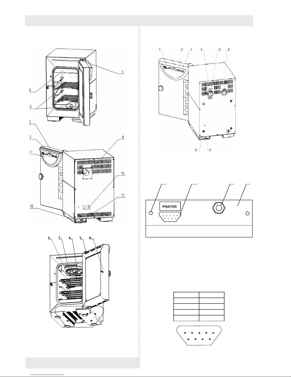
GENERAL VIEW
Fig. 2
1 - controller panel
2 - control keys
3 - plastic cover of the controller panel
5 - lever for air ap positioning
6 - case of PT 100 sensor
7 - fan (only for VC, ICV)
8 - exhaust with air ap (with all types)
9 - heating elements
10 - power board I
11 - power board II (only three-phase type)
12 - mains cord
14 - door sensor
15 - suction hole (only for VC, ICV, with air ap)
16 - suction hole (with types EC, DC, IC)
X
(H)
X (V)
2
X (V)
1
X (Š)
Instructions for use
LSI-S_np_en_1309_mmm_V2.10_B2V 5
ECOCELL 22
VENTICELL 22
Instructions for use
PŘEBÝVÁ POZICE 4
1
2
3
4 5
6
7
8 9
6 LSI-S_np_en_1309_mmm_V2.10_B2V
VENTICELL 22
3.2
POWER CONNECTION AND
CONNECTORS
1 2
3
4
Fig. 5:
Foot of the unit with mains cord
- rear view (with the power board I)
1 - Interface for printer
2 - Mains supply
3 - Screws attaching the power board
4 - Power board panel (located in the foot)
9 Canon connector on the case
Pin Signal
2 RX
3 TX
5 GND
6 DSR
1
2
3
4 5
6
7
8 9
Fig. 6: 9 Canon - Interface for protocol printer
25 Canon connector in the printer
Pin Signal
2 TXD
3 RXD
7 GND
20 DTR
The appliances, which are connected with the
connector RS-232C, must comply with valid
regulations in terms of electric safety and
electromagnetic compatibility.
Interface parameters: Baud 9600
Stopbit: 1
Parity: none
Databit: 8
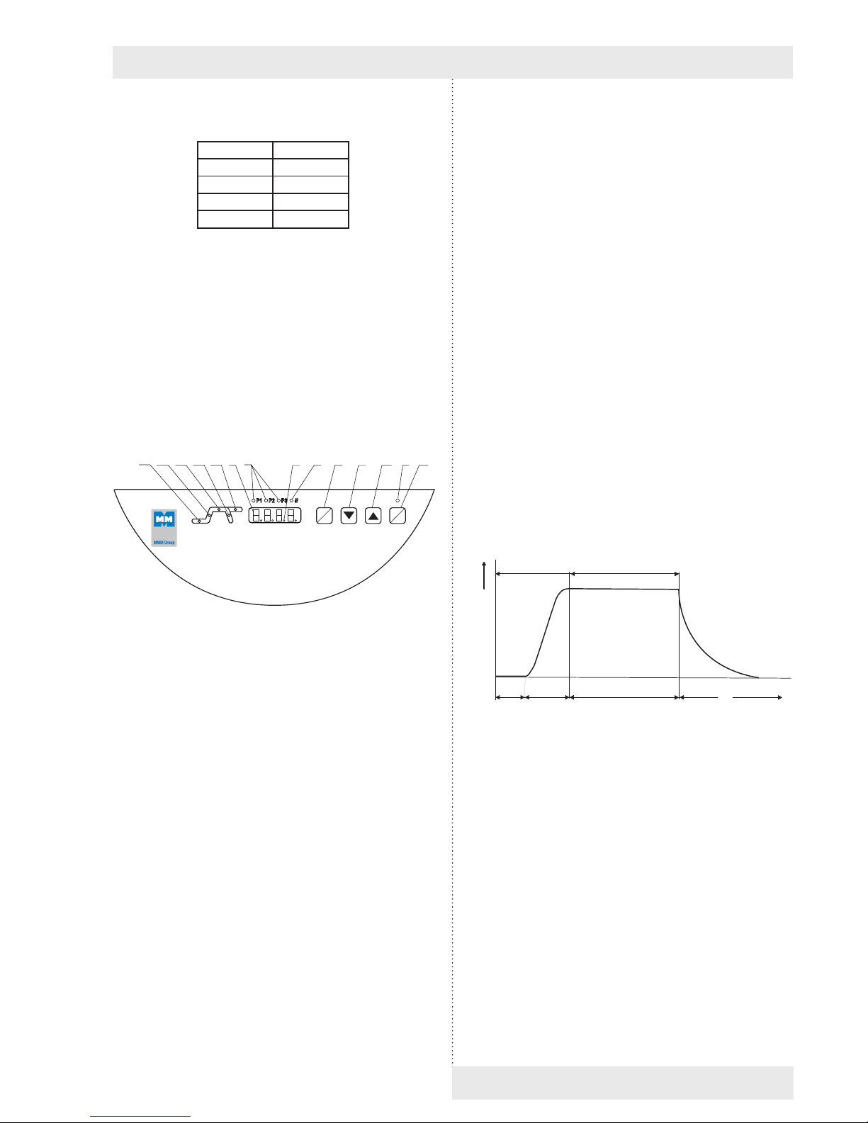
3.3
CONTROL PANEL
Fig. 4
1 - display
2 -
decimal point - burns (the unit is
connected to the mains - stand-by mode)
3 -
the indicators of pre-selected programs:
- burn: program is active
- blink: program will be active in 5 sec.
5 - heating indicator light - burns:condition of
temperature regulator - heating active
6 - power indicator light - burns after
switching the unit on by ON/OFF swich
7 - Safety system indicator is ashing: The
temperature exceeded the chosen limit set
by the protective thermostat – the heating
is switched off (see more in Chapter 4.6
Safety System Functions and Setting)
8 - setting mode activation key
9 - setting the value downwards
10 - setting the value upwards
11 - switch (ON - switched on, OFF - stand by mode)
14 - Indicator light: blinks - set-up
mode, burns - the active part of the
program is time-delayed switching-on
Instructions for use
15 - indicator light: blinks - set-up mode,
burns - the active part of the program is
heating-up to present temperature
16 - indicator light: blinks - set-up
mode, burns - the active part of the
program is time-delayed switching-off
17 - Indicator light: blinks - set-up
mode, burns - decrease of temperature
after switching-off
18 - Indicator light: blinks - set-up mode,
burns - the active part of the program is
innite stay on the present temperature.
Indicator lights 14-18 blink - number of cycles
setting mode.
4
function and
operating
The unit can be set to various modes according
to the required function, i.e. the unit’s cycle can
be modied, as described below. In the gure a
complete course of one cycle with its stages is
shown.
t (x)
t
(°C)
0
a b t (min)c
Segment Funktion
0 time-delayed switching-on,
a rise to the temperature,
b time-delayed switching-off
c temperature drop after switching off
The functions of the respective indicator lights
are described in chapter 3 - Description of the
Unit, and 3.3 - Control Panel.
4.1
STARTING AND SWITCHING-OFF
1. In case, that the unit was in the stand-by mode
before switching-off, a green dot in the right
lower part of the display will lit up, otherwise
the program, interrupted by switching off, will
continue.
x
w
ON
OFF
14 15 16 17 18 1 3 2 5 8 9 10 6 11
LSI-S_np_en_1309_mmm_V2.10_B2V 7

Instructions for use
8 LSI-S_np_en_1309_mmm_V2.10_B2V
2. Press the key ON/OFF. The indicator light
above the key, the indicator light of the preselected program and the indicator light of the
initial active program stage will lit up.
If the temperature in the chamber will be lower
than the preset value, the heating indicator
light will burn as well - either permanently
or blinking (depending on heating controller
status - on or off).
3. Press the key ON/OFF. The display turns off,
only the green indicator light in the lower right
part is on (stand by). The total disconnection
from mains (in case of a long-term putting out
of operation or a maintenance) is achieved
by pulling the mains cord from a socket – see
also chapter Before installation.
4.2
SETTING-UP THE REQUIRED
VALUES OF TEMPERATURE,
TIME-DELAYED SWITCHING-OFF,
NUMbER OF CYCLES, TIME-
DELAYED PROGRAM START
1. Set the pre-selection of the program 1or 2 or
3 by pressing the key ▼ or ▲, after pressing
the key ▼ or ▲the indicator light of the next
program will start to blink. This program will
be activated in ca. 5 sec, if no other key is
pressed during this time. Setting by means
off ▼ or ▲, will cause the stop of the actually
running cycle and starting a new cycle with the
pre-selected parameters. The setting-up cycle
begins with setting the required temperature.
2 Press the key X/W, indicator lights 15, 16
(Fig.4) start to blink, by pressing the keys ▼▲
set the required temperature in °C on the display.
The lowest temperature interval, which can
be set and displayed with EC, DC, VC is 1 °C;
with IC, ICV it is 0,1 °C.
The indicator lights of the segments blink
permanently.
3. By pressing the key X/W change over to
the setting of time-delayed switching-off, by
pressing the keys ▼▲set the required value
in hours and minutes from 0 to 99 hrs and
59 min on the display, thereby the indicator
lights 16, 17 (Fig.4) blink. The symbol --corresponds to the timely unlimited exposure.
4. By pressing the key X/W change over to the
setting of number of cycles and by pressing
the keys▼▲ set the number of cycles from
1 up to 255 (more information on the cycles
see 4.3) - all indicator lights blink during the
setting up.
This function can be used only with the time-
delayed switching-off ≠ 0.
Select the option of cycles setting by using the
user menu.
5. By pressing the key X/W change over to the
stage of setting the time-delayed starting and
by pressing the keys ▼▲ set the required
value in minutes from 0 up to 99 hrs 59 min,
the indicator light 14 (Fig.4) blinks.
6. Start the program by double pressing the key
ON/OFF (the program start is announced by
an acoustic signal). Actual temperature with
time countdown will blink on the display during
the time-delayed program starting.
The heating is switched on after reaching the
time of zero and the display shows the actual
temperature in the chamber.
After reaching the required temperature:
a) in case of setting the time-delayed shut
down, the chamber temperature with the
preset time countdown starts to change on
the display or
b) in case of time unlimited switching-off, the
chamber temperature with the count up
time starts to change on the display. After
99 hours:59 min pass, time is displayed in
hours up to 999 hours. It is then displayed
by ∞ symbol (innity). When printing the
record on the printer, time is shown up to
999:59; the text “inni” is then printed.
Continuously lighting indicators inform about
the actual active phase of the programme.
The permanently lighting indicator lights
provide information on the actually active
program stage.
7. Individual values can be checked during the
program run - by pressing the key X/W the
required value is shown on the display, the
indicator lights blink, by the next pressing of
the key X/W within 5 seconds you will change
over to the next stage, in this way all settings
can be checked step by step.
The original program will continue, if no control
element within 5 seconds will be used.
8. In the similar way, you can change the already
set values during the programme operation, if
a) you will wait ca 5 second after setting of
new values, the programme continues with
changed values from the break point.
b) after setting the value you can start the
program by double pressing the key ON/OFF,
the program will start with new values from the
beginning.
Fan run and program end:
With all types containing fan the fan runs for
5 minutes after the program end and then it is
switched off.
 Loading...