

Laboratory drying ovens and incubators
line Standard
VENTICELL 55, 111, 222, 404, 707
INCUCELL 55, 111, 222, 404, 707
INCUCELL V 55, 111, 222, 404, 707
ECOCELL 55, 111, 222, 404, 707
STERICELL 55, 111, 222, 404
DUROCELL 55, 111, 222
Operating instructions
MMM Medcenter Einrichtungen GmbH producer:
MMM Medcenter
Einrichtungen GmbH
Schulstrasse 29
D – 82 166 Gräfelfing
Tel.: +49 89 89 92 26 20
Fax: +49 89 89 92 26 30
LSI_S_en_np 0402_mmm V 1.09 Blue Line

Operating instructions Ovens line Standard Page
Contents:
10. 2. 2004
1 GENERAL ...................................................................................................................................... 3
1
1.1 P
URPOSE AND USE....................................................................................................................... 3
2 IMPORTANT INSTRUCTIONS ...................................................................................................... 3
2.1 U
2.2 P
NPACKING, CHECKING AND TRANSPORT ....................................................................................... 3
RE-INSTALLATION ....................................................................................................................... 4
2.3 USEFUL SPACE ............................................................................................................................. 6
3 DESCRIPTION OF THE OVEN...................................................................................................... 7
3.1 G
ENERAL VIEW ............................................................................................................................. 7
STERICELL 55~404 - PLACING THE HEPA FILTER, FILTER DIMENSIONS, FUNCTION AND FILTRATION
CHARACTERISTIC OF THE AIR FILTER
....................................................................................................... 8
3.3 POWER CONNECTION AND CONNECTORS........................................................................................ 9
3.4 CONTROL PANEL......................................................................................................................... 10
4 FUNCTION AND OPERATING.................................................................................................... 11
4.1 S
WITCH-ON ................................................................................................................................11
4.2 SWITCH-OFF............................................................................................................................... 12
4.3 U
SER'S SUPPORTING FUNCTIONS................................................................................................. 12
4.4 SETTING-UP REQUIRED VALUES OF TEMPERATURE, TIME-DELAYED SWITCHING-OFF, NUMBER OF
CYCLES
, TIME-DELAYED SWITCHING-ON. ............................................................................................... 12
4.4.1 Sterilization program setting and run - for STERICELL only.......................................... 14
4.5 L
IST OF ERROR MESSAGES .......................................................................................................... 15
4.6 PRINTING THE PROTOCOL............................................................................................................ 15
4.7 F
UNCTION AND SETTING OF THE SAFETY THERMOSTAT.................................................................. 16
4.8 ADJUSTING AND FUNCTION OF THE AIR FLAP ................................................................................. 17
4.9 EXCHANGING THE DOOR SEALING AND ADJUSTING THE DOOR ........................................................ 18
5 PARAMETERS OF THE APPARATUS....................................................................................... 19
5.1 E
LECTRIC CONNECTIONS............................................................................................................. 20
6 CLEANING OF THE OVEN ......................................................................................................... 20
7 MAINTENANCE ........................................................................................................................... 20
8 WARRANTY AND SERVICE ....................................................................................................... 21
9 TRANSPORT AND STORAGE.................................................................................................... 21
10 THE WAY OF LIQUIDATION OF PACKAGE AND DISCARDED APARATUS ......................... 21
11 OPTIONAL EQUIPMENT............................................................................................................. 21
11.1 D
OOR WITH WINDOW AND INNER LIGHTING (EXCEPT IC, ICV).................................................... 22
11.2 BUSHINGS OF DIAMETER 25, 50, 100 MM ................................................................................ 24
11.3 LOCKABLE DOOR .................................................................................................................... 24
11.4 L
EFT DOOR ............................................................................................................................ 24
11.5 INDEPENDENT SENSOR PT100................................................................................................ 24
11.6 C
11.7 HEPA
OMMUNICATION SW DS COM FOR PC UNDER WINDOWS ...................................................... 24
FILTER ........................................................................................................................ 25
11.8 TWO-DOOR PASSING THROUGH VERSION ................................................................................. 25
11.8.1 Two-door STERICELL 404 - installation data ................................................................. 25
11.9 A
DAPTATION AGAINST DRYING-UP OF CULTIVATING MEDIUMS AND TISSUE CULTURES.................. 29
LSI_S_en_np 0402_mmm V 1.09 Blue Line

Operating instructions Ovens line Standard Page
2
V 1.09 Blue Line LSI_S_en_np 0402_mmm

Operating instructions Ovens line Standard Page
1 General
The ovens with electric heating are designed for laboratories, generally for a warming of
various materials by means of hot air at adjustable temperature and optional time. The air
flap enables drying of wet material.
A modern microprocessor (Fuzzy - logic) with a digital display and PT 100 controls the
temperature. Thus exact temperature accuracy and process safety are guaranteed.
The ovens are designed according to EN standards.
They are manufactured of high grade materials with the latest technology.
Each oven is subjected to a strict final test leaving the plant.
1.1 Purpose and Use
VENTICELL (VC) serves for warming of materials by means of hot air with forced-air
circulation by a fan. The ovens are designed for temperatures up to 250 °C, another variant
(+) up to 300 °C.
3
INCUCELL (IC, ICV) serves as an incubator or for cell cultivation in a microbiological
laboratory (see chapter Optional equipment, article Adaptation against drying-up of
cultivating mediums and tissue cultures). The ovens are designed for temperatures up to 70
°C. A quiet operation is characteristic for the variant IC (without a ventilator), more accurate
temperature regulation with small deviations is characteristic for the variant ICV (with
ventilator).
ECOCELL (EC) serves for warming by hot air with natural circulation. The ovens are
designed for temperatures up to 250 °C. They work quietly with lower power consumption
compared with VC units.
STERICELL (SC) serves for sterilizing by hot air with forced-air circulation by a fan. The
ovens are designed for temperatures up to 250 °C. STERICELL uses time-delayed switchoff program for sterilizing, refer to section Set and Running the Sterilizing Program.
DUROCELL (DC) serves for warming by hot air with natural circulation (usefull at procedures
as acid hydrolysis, extraction by nonflammable solvents, thermolysis). The ovens are
designed for temperatures up to 125 °C. Internal surface is covered by a layer of EPOLON,
that protects the chamber against corrosive influence of acids in the form of vapors or liquids.
2 Important Instructions
2.1 Unpacking, checking and transport
Please check after unpacking the oven and its accessories are complete and not damaged.
A possible damage is to be reported to the forwarding agent. An eventual damage must be
immediately reported to the transporting company.
LSI_S_en_np 0402_mmm V 1.09 Blue Line
Operating instructions Ovens line Standard Page
During the manipulation – in case of lifting the cabinet etc. – the cabinet cannot be hold by
the rail or door. The cabinets of volumes 404 and 707 should be lifted by means of delivered
hooks, the rolls are designed for local moving, not for longer transport.
The standard delivery consists of the temperature cabinet, two sieves.
2.2 Pre-installation
♦ Please read carefully the operating instructions before working with the oven!
♦ Install the instrument by plugging the power cord to a line voltage socket. The specified
parameters of the connection are described in chapter Electrical Connection. Adjust the
position of air valve according to chapter Air Valve - Adjustment and Functions. For
VC, SC and ICV types, adjust two air valves – suction and exhaust.
After the first switching-on of the unit the heating bodies and insulation start to be
baked with a typical a smell; after a few operation cycles this smell disappears,
nevertheless it is suitable, during the insulation baking at a temperature above 100°C,
to secure a sufficient air exchange (e.g. by ventilation or exhaustion).
At temperatures above 100 °C the inner chamber surface becomes yellowish. This
coloration is neither the material nor the device defect.
4
The air exhaust in VC, EC a SC types is protected by a cover rear of the unit. This
cover is placed inside the oven while shipping. When installing the unit, insert the
cover into the horizontal openings bellow and above the exhaust to attach it behind
the exhaust.
An air filter can be connected to the suction hole in SC types - see section
Function and filtration characteristics of the air filter.
Ovens are designed to be operated indoor within ambient temperatures from 5 °C to
40 °C and at maximum relative humidity 80 %.
The oven should be installed with a 100 mm distance to the walls at the side and in
back. The temperature of the air coming out of the exhaust may be up to 250 °C
(resp. 300 °C), so the walls near the oven must be inflammable
.
No inflammable or explodable materials may be put into ovens !
Carrying capacity of the floor during installation of the device must correspond to the
weight of the unit itself taking the weight of the maximum charge into consideration
(see chapter Parameters of the unit).
The unit must not be placed on a pad that could cause a danger of fire or smothering
in case of falling some hot object out of the cabinet.
No inflammable, explosive or toxic materials may be put into ovens! The same
applies to materials that could give off such a stuff.
Goods are only to be put on trays into ovens, never directly on the bottom of the oven!
No dangerous goods are permitted. Ovens may not be used for heating of liquids.
V 1.09 Blue Line LSI_S_en_np 0402_mmm
Operating instructions Ovens line Standard Page
Aparatus may not be used in the atmosphere with a possible danger of flammable or
explosive anesthetics.
Any assembling or disassembling may be done only when disconnected from
mains! After the button (button 11, fig. 4) activates the stand-by state, the oven
comes only to a stand-by state, however it is not disconnected from the mains!
♦ If the oven is not used for a longer time, disconnect it from mains by pulling the service
cord from the socket
Power cord can not get to the contact with hot parts of the aparatus – protection
cover of exhaust hole
♦ Safety thermostat assures the protection of the oven, surroundings and goods against
surpassing the rated temperature. Protection through temperature safety class 2
according to EN 61010-2-010 is for VC and EC, protection through temperature
safety class 3 according EN 61010-2-010 cs for IC, ICV. Check regularly – daily – the
function safety thermostat.
♦ The door and the exhaust air flap in SC type are provided with microswitches - see
section Setting and running the sterilizing program.
5
Pull out and consequently push in the upper metal plate piece of internal chamber
carefully, there is a danger of cutting through the rubber gasket of the chamber during
careless manipulation.
The maximum permitted loads: see section Parameters of the unit.
Only for STERICELL
The units of STERICELL 404 are provided with a door lock – for securing the safety.
You can enter the chamber, e.g. because of cleaning, only if the door is locked
(blocked) in an open state. You must keep the key all the time you find yourself inside
the chamber.
When operating the cabinets at high chamber temperature there can be the
maximum allowed temperature of 70 °C at their outer surface (exhaust ports and their
surroundings and the surroundings of the chamber sealing, window and door surface
in case of the optional type with window in door) surpassed and there is a danger of
burns. Please take a high precaution.
During the operation of the devices of 404 and 707 at high temperatures a
deformation of the inner door surface occurs as a consequence of thermal tension,
which makes their closing more difficult. If you open the door in this state, do not
close them until the chamber is cooled down. Otherwise the door mechanism could
be damaged.
LSI_S_en_np 0402_mmm V 1.09 Blue Line
Operating instructions Ovens line Standard Page
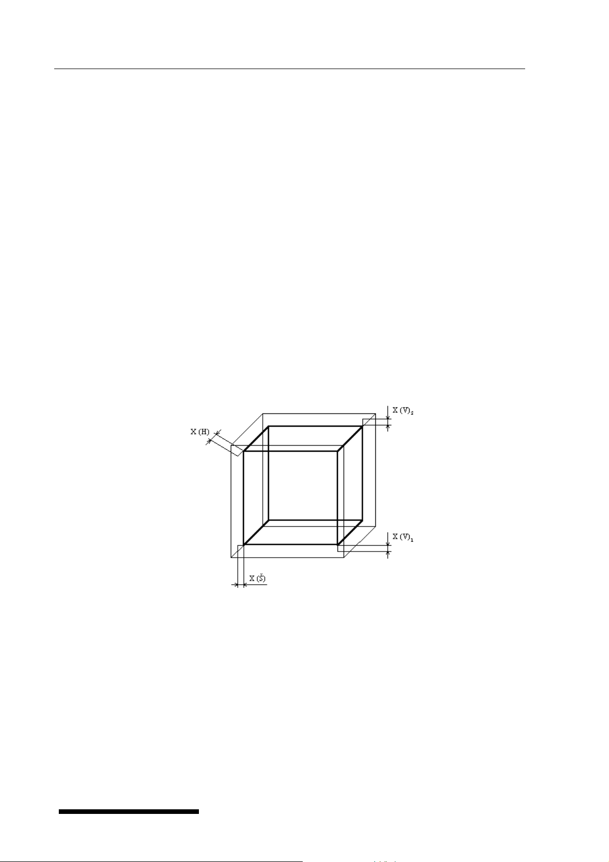
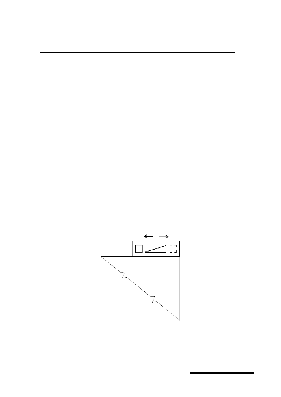
2.3 Useful space
Useful space is illustrated on fig. No. 1, where X(H) = 10 % of the inner chamber depth,
X(Š) = 10 % of the inner chamber width, X(V)
bottom of the inner chamber, X(V)
is the distance from the upper most tray to the ceiling of
2
the inner chamber. The required temperature accuracy - see section Parameters of the unit
- is achieved only in the space defined above (according to DIN 12 880 - marked with thick
lines, thin lines mark inner chamber walls). It means, that over the last upper tray there are
the limits from section 5. not obligatory.
For Stericell following definition of the sterilizing space is valid:
at the side to the door is X(D) = 20 % of the inner chamber depth, at the rear side in the
single-door type X(D) = 10 % of the inner chamber depth, X(W) = 10 % of the inner chamber
width, X(H)
is the distance from the lowest tray to the bottom of the inner chamber, X(H)2 is
1
the distance from the upper most tray to the ceiling of the inner chamber. The required
temperature accuracy - see section Parameters of the unit - is achieved only in the space
defined above (according to DIN 12 880 - marked with thick lines, thin lines mark inner
chamber walls). It means, that over the last upper tray there are the limits from section 5. not
obligatory.
is the distance from the lowest tray to the
1
6
Fig. 1
V 1.09 Blue Line LSI_S_en_np 0402_mmm
Operating instructions Ovens line Standard Page
)
3 Description of the oven
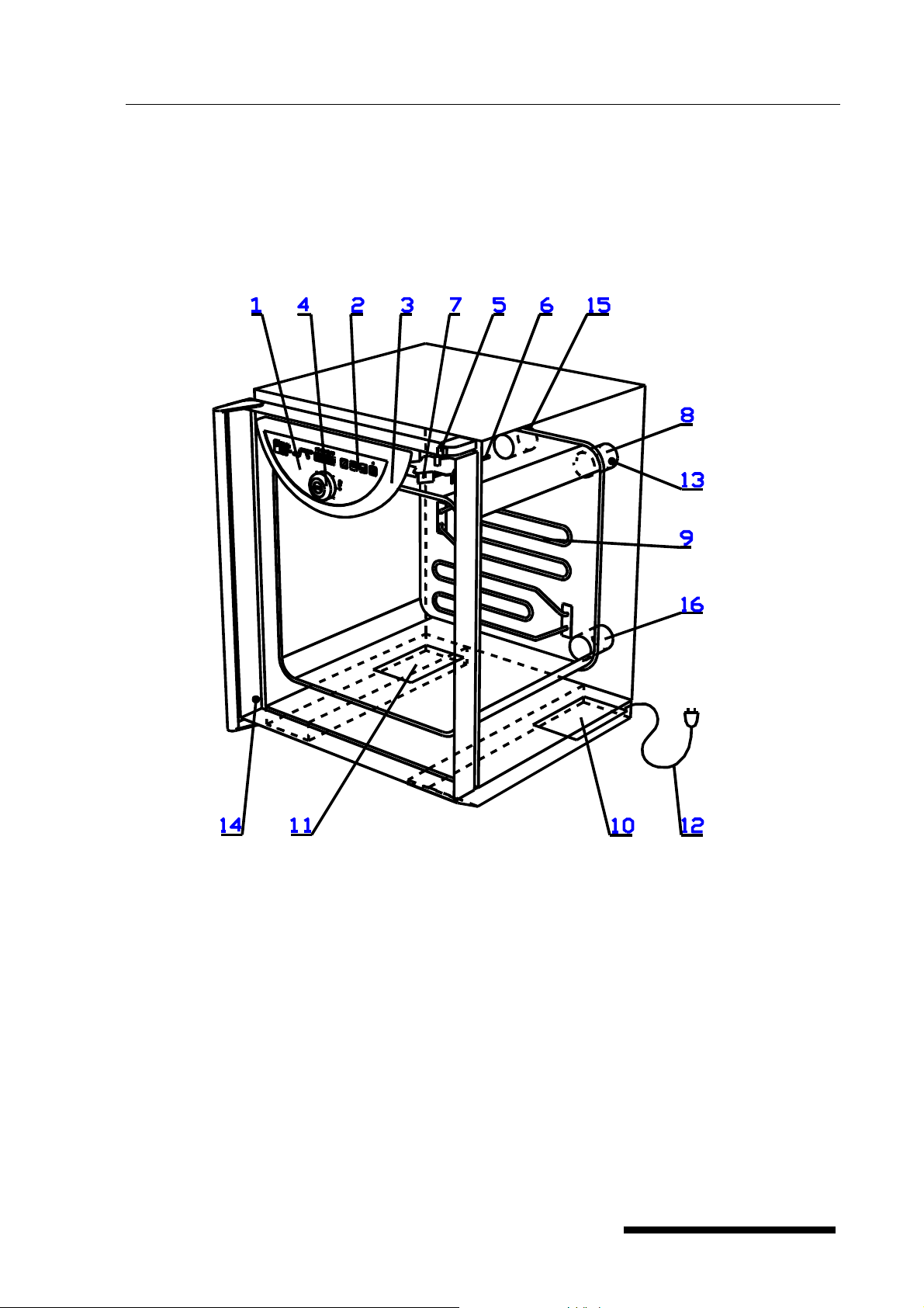
3.1 General view
7
Fig. 2
1 Panel of regulator 2 control buttons
3 Plastic cover of the regulator panel 4 control ring and button of
safety thermostat
5 air flap lever 6 case of sensor Pt 100
7 Ventilator (only for VC, ICV a SC) 8 exhaust with air flap (with
all types)
9 Heating elements 10 Power part I
11 Power part II (only three-phase type) 12 Connection to the mains
13 Sensor for air flap position (only for SC) 14 door sensor (only for SC)
15 Suction hole (only for VC, ICV, SC with air flap) 16 suction opening (with types
EC, IC, DC
LSI_S_en_np 0402_mmm V 1.09 Blue Line
Operating instructions Ovens line Standard Page
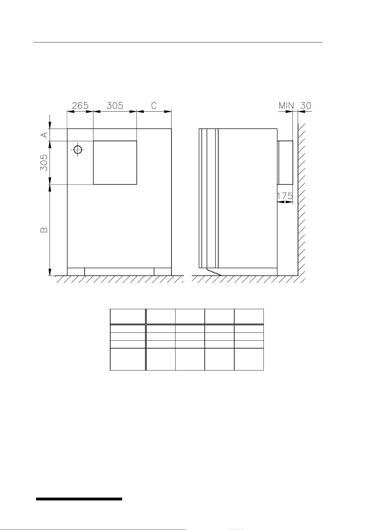
3.2 STERICELL 55~404 - placing the HEPA filter, filter dimensions, function
and filtration characteristic of the air filter
8
fig. 3
Type/
Dimens.
A (mm) 85 85 85 135
B (mm) 290 470 710 1470
C (mm) 50 190 190 190
Height
A+B+305
(mm)
55 111 222 404
680 860 1100 1910
Note: The minimum distance from the filter to the wall is 30 mm.
The air filter is a part of the optional accessories, it is installed when cooling STERICELL by
forced air circulation.
Class of the HEPA filter according to DIN 24 184 is S, according to EUROVENT it is EU 12.
V 1.09 Blue Line LSI_S_en_np 0402_mmm

Operating instructions Ovens line Standard Page
3.3 Power connection and connectors
Fig. 5 Foot of the unit with power supply - rear view (with the power part I)
9
1 Socket for printer
2 Supply lead
3 Screws attaching the power part
4 The power part panel (placed in foot)
Fig. 6 Interface for protocol printer
Pin Signal
2 TX
3 RX
5 GND
6 DTR
Ovens connected by RS-232C connector must meet the regulations and be approved
by the testing laboratory. Ovens are designed for connecting a CITIZEN printer, type iDP
3110-24 RF-A which can be ordered with the oven.
Interface parameters
Baud: 9600
Stopbit: 1
Parity: none
Databit: 8
LSI_S_en_np 0402_mmm V 1.09 Blue Line
Operating instructions Ovens line Standard Page
p
g
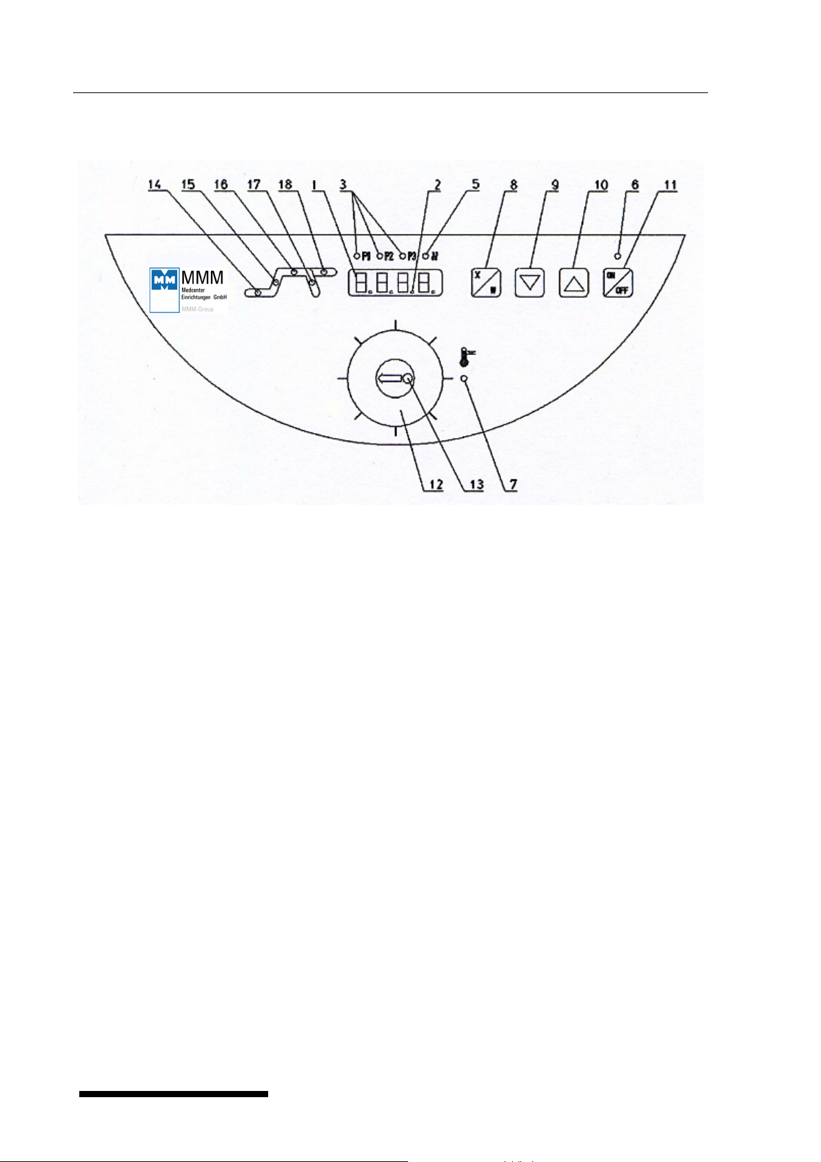
3.4 Control panel
10
Fig. 4
1 Display
2 decimal point - lights (the unit is connected to the mains - stand-by condition)
3 preselected programs indicator lamps- lights: program is active
- blinks: program will be active in 5 sec.
5 heating indicator lamp - lights:condition of temperature regulator - heating active
6 switching-on indicator lamp - lights after switching the unit on by the depression of
ON/OFF
7 protection thermostat indicator lamp - lights:temperature exceeds the selected setting
limit of the protecting thermostat - heating is off/further information see
chapter 4.8.Protecting thermostat function and setting-up
8 Setting-up mode activation button
9 setting the value downwards
10 setting the value upwards
11 switch ( ON – switched on, OFF - stand by condition)
12 adjustable protecting thermostat - outer rotary ring
13 button (RESET) to set the protecting thermostat in operation again
14 Indicator lamp: blinks - setting-up mode, lights - active part of the program is time-
delayed switching-on
15 Indicator lamp: blinks - setting-up mode, lights - active part of the program is heating
upto set temperature
16 Indicator lamp: blinks - setting-up mode, lights - active part of the program is time-
delayed switching-off
17 Indicator lamp: blinks - setting-up mode, lights - decrease of temperature after
switching-off
18 Indicator lamp: blinks - seting-up mode, lights - active part of the program is infinite
stay on set-up temperature
Indicator lam
s 14-18 blink - mode of number of cycles settin
V 1.09 Blue Line LSI_S_en_np 0402_mmm

Operating instructions Ovens line Standard Page
4 Function and operating
The unit can be set to various modes according to the required function, i.e. the unit’s cycle
can be modified, as described below. In Fig. a complete course of one cycle with its
segments is shown.
11
Segment Function
0 time-delayed switching,
a rise onto the temperature,
b time-delayed switching-off,
c temperature drop after switching off
Function of the control lights is described in section Description of the unit, in paragraph
Control panel.
4.1 Switch-on
1. After connection to the mains a green dot in the right lower part of the display lights
(stand-by condition) in case that the unit was in the stand-by mode before switching-off;
in contrary case the program continues by the part of the program which was
interrupted before switching-off.
2. Before switching-off.Depress button
lamp of one of preselected programs and indicator lamp of initial active phase of the
program light up; if preset temperature is higher than that in the chamber,the heating
indicator lamp lights also - either permanently or intermittently (depending on switched on
or switched off heating regulator).
3. The display displays real data relating to active phase of the program.
indicator lamp above the button, indicator
LSI_S_en_np 0402_mmm V 1.09 Blue Line

Operating instructions Ovens line Standard Page
4.2 Switch-off
Press the key . The display turns off, only the green control light in the lower right part is
on (stand by). The total unplugging from mains (in case of a long-term putting out of
operation or a maintenance) is achieved by pulling the service cord from a socket – see also
chapter Pre-installation.
4.3 User's supporting functions
Enter the function by simultaneous depressing +
By means of set on the display
12
a) U1 - setting the period of print of the printer from 0 up to 255 min by means of
enter the setting by means of
b) U2 - ON or OFF - set permission or prohibition of cycles by means of (for all
pre-selections at the same time), enter the setting by depressing
multiple repetition of the program with set time-delayed switching-off and switchingon.
Leave the setting by depressing
c) U3 – Prn or PC – data transfer via interface RS 232 either on the printer (Prn) or, in case
of using the program Warmcomm, on the computer (PC); set the sign Prn or PC by means
of.
d) U4 – reserve
e) U5 – permission (Y) or prohibition (n) of the acoustic signalizing at the exposure end (in
case of cycling after the end of the last cycle). The acoustic signal consists of three
consequent tones (between individual cycles one short high beep is heard). The primary
setting prohibits the acoustic signalizing.
and leave the function by depressing .
; a cycle means
,
4.4 Setting-up required values of temperature, time-delayed switching-off,
number of cycles, time-delayed switching-on.
1. Set preselection of program 1 or 2 or 3 by means of or , after depressing or
the control lamp of further program starts to flicker. This program will be activated
within ca. 5 sec, if no other button is depressed during this time. Setting by means of
or will cause the stop of the running cycle and starting a new cycle with the preselected parameters.
Setting-up cycle begins with setting required temperature.
V 1.09 Blue Line LSI_S_en_np 0402_mmm

Operating instructions Ovens line Standard Page
13
2. Depress , indicator lamps 15, 16 (Fig.4) begin to flicker, by means of set
required temperature in °C on the display
The lowest adjustable and displayable temperature interval with VC, EC, SD, DC is
1 °C with IC, ICV it is 0,1 °C.
Indicator lamps of the segments flicker permanently.
3. By depressing
off, by means of
change to the segment of setting the time-delayed switching-
set required value in hours and minutes from 1 to 99 hrs 59
min on the display, indicator lamps 16, 17 (Fig.4) flicker. The symbol --- corresponds to
the unlimited exposure.
4. By depressing
means of
change to the segment of setting the number of cycles and by
set the number of cycles from 1 up to 255 (more information on the
cycles see 4.3) - all indicator lamps flicker during setting up.
This function can be used with time-delayed switching-off ≠ 0 only.
Set the possibility to select the cycles by means of the user's supporting function.
5. By depressing
on and by means of
change to the segment of setting the time-delayed switching-
set the required value in minutes from 0 up to 99 hrs 59
min, indicator lamp 14 (Fig.4) flickers.
6. Start the program by double depressing
(start of the program is announced by an
acoustic signal). Data on real temperature with time count-down flickers on the display
during the phase of time-delayed switching on. The heating is switched on after
reaching the time of zero and the display shows the real temperature in the chamber.
After reaching the required temperature
a) in case of setting the time-delayed switching-off, the chamber temperature with the
set time count-down begins to flicker on the display
b) or in case of unlimited switching-off, the chamber temperature with the rising time
flicker on the display.
Permanently lighting indicator lamps give information on just active program segment.
7. Individual set values can be checked during the run of the program - by depressing
the required value is shown on the display, indicator lamps flicker, by another
depressing
within 5 seconds you change to the next segment, in this way all
settings can be checked successively.
Original program continues if you use no control element within 5 seconds.
8. Similarly, during the course of the program, you can change the already set values,
when
a) after setting the last value - time-delayed switching-on - you wait approximately 5
seconds, the program continues with changed values from the point of interruption,
b) after setting the value you start the program by double depressing
, the program
starts with new values from the beginning.
LSI_S_en_np 0402_mmm V 1.09 Blue Line
Operating instructions Ovens line Standard Page
4.4.1 Sterilization program setting and run - for STERICELL only
Data in previous paragraphs hold for setting and run.
Temperature °C Sterilization exposition in minutes
160 60
170 30
180 20
1. After the last depressing of the setting button the unit starts the first set segment
automatically. During this program phase (segment 0 and a ) the automatics permanently
checks the condition of the door and of the air flap. If the door or the air flap is open,
temperature and the message open flicker on the display. After closing the door and/or
the flap the message disappears.
2. A few seconds after reaching the sterilization temperature (this may be even with a
certain delay as compared with the data on the display) the set sterilization time begins to
be counted down – time-delayed switching-off (phase b). During this phase the
automatics permanently checks the condition of the door and of the air flap. If the door
or the air flap is open, the phase continues and the display shows the message open
and chamber temperature data alternately.
If the door or the flap is not closed, the unit switches off after the set exposure time is
reached and the display shows open/end and the temperature alternately, you can
14
cancel the message by double depressing
.
After closing the door or the air flap, segment b (or a - according to the real temperature
in the chamber) starts automatically from the beginning again.
If the temparture drops during this phase below the set value, the display indicates error
2.
3. The heating switches off after reaching the set time, indicator lamp 17 lights, the unit
starts to cool down (phase c) and the display shows the value of real temperature
and the note end alternately. Function of all buttons except of the switch (button 11, Fig.
4) is locked. Unlocking is done by opening the door or the air flap or by depressing
Then the note end disappears and the unit is in the stand-by mode.
4. If we want to repeat such set cycle, we activate the unit without setting by single
depressing
. The unit starts to run.
5 Warning! When starting a sterilization cycle - or in case of a set time-delayed switching-off,
the temperature in the chamber must be lower than the required one. Otherwise you
induce an error 3 message.
Note:
a) Because the STERICELL ovens are especially designed for sterilizing purposes, the
sterilization temperature within the sterilization space (definition see chapter Useful
space) is maintained with accuracy from -1 to +5 °C. The information on the display and
on the printer agrees with the real chamber temperature.
b) For sterilization of greater amount of small packed objects special holders of these objects
can be ordered.
.
V 1.09 Blue Line LSI_S_en_np 0402_mmm

Operating instructions Ovens line Standard Page
15
c) After reaching the set sterilization temperature and after the start neither the temperature
can be changed nor the program switched over.
d) In case of messages Err 2 and Err 3 you can cancel them by depressing
for ca. 2
seconds; the display shows brk (break) and the chamber temperature data alternately.
You can change the parameters or switch over the program or let the chamber cool down
in this condition. Start the new setting by depressing
.
Ventilator run and program end:
With all types containing ventilator the ventilator runs for 5 minutes after the program end
and then it is switched off.
4.5 List of error messages
Err 1 - not calibrated (the service engineer performs compensation of measuring conduits
of the sensor).
Err 2 - drop of temperature below sterilization temperature (only in case of SC, the function
is activated only with set time-delayed switching-off , deactivate setting by
cancelling)
Err 3 - rise of temperature above sterilization temperature (only in case of SC, the function
is activated only with set time-delayed switching-off, deactivate setting by
cancelling), or real temperature in the chamber is above set temperature.
Err 4 - Err 10 - HW error (report this event to the producer)
4.6 Printing the protocol
Printing the protocol with the help of CITIZEN printer, type iDP 3110-24 RF-A. Setting the
interval on a printer will decide at what interval the actual value of the chamber temperature
will be printed. The time of the interval will be printed on the head of the extract.
The interval of the printer can be set within: t
after 1 minute.
1. The display indicates the actual temperature. Connect the printer to the cabinet by the
RS-232C connector into the printer’s receptacle (see fit, 4), connect the other ending of
the cable to the connector rear of the printer. Connect the printer to mains by connecting
the adapter AC 230 V, 50 Hz, 0,1 A/DC 7 V, 1,6 A into the socket on the back side of the
printer and plugging the adapter into the wall socket. Turn the switch on the right side of
the printer off. The control light POWER and SEL is turned on. The printer is in ON-LINE
mode. Paper will start moving on by pressing the key LF (only in mode OFF-LINE, that is
after pressing the key SEL, the control light SEL switches off. To restore the mode ONLINE press the key SEL, the control light SEL switches on). The printer prints only in the
mode ON-LINE!
2. Set the required interval upwards or downwards according to Setting-up required
values of temperature.
3. The printer prints the heading containing type of the unit, set temperature and
selected time interval. Values of the following data are printed in one line under this
heading: time from starting the program and actual temperature in the chamber.
4. Switching the print off is performed by setting the print interval to 0 (symbol ---).
5. In case of change of set operation conditions of the oven or in case of change of print
interval a new heading will be printed (this is not valid when set interval is 0 (symbol---).
LSI_S_en_np 0402_mmm V 1.09 Blue Line
= 1 minute, t
min
= 255 minutes (4 hr. 15 min.),
max

Operating instructions Ovens line Standard Page
6. If the power supplying the apparatus fails , after the power recovery the printer prints the
sign Æ Power recovery! and the actual temperature value. Time intervals start counting
immediately after power recovery. After the unit has been turned off and turned on again,
a new head is printed.
7. If the power supplying the printer fails or the printer is turned off, no message is printed
after turning the printer on again or after power recovery .
Setting of the DIP / switches of the printer: all four pins are in lower position OFF.
4.7 Function and setting of the safety thermostat
The safety thermostat protects the oven, its surrounding and the goods against surpassing
the set temperature (for example it prevents the goods samples to be damaged or destroyed
when the temperature regulator is damaged or when you set unintendedly a chamber
temperature, which the sample cannot withstand).
Setting the thermostat:
Set the safety thermostat to a temperature higher then the rated temperature. The thermostat
turns off 5 to 10 °C higher than the set temperature (because of the temperature inertia of the
chamber material, and according to the heating-up time to the “switch-off’ temperature whether it is slow or quick).
16
Follow these steps to set the thermostat:
1. Push the outer revolving ring towards the operating panel. While slightly pressing rotate to
the right (clockwise) to the maximum. Together with the outer ring the center with the
button is rotating.
2. Heat the oven up to the working temperature and leave it for 10 minutes at this
temperature.
3. Now rotate the ring to the left - counterclockwise - (the same way as in the step 1) until the
control light protective thermostat comes on. At this moment the set temperature is
reached.
4. After that turn the ring to the right a little and press the thermostat button. You will hear a
“click“ and the control light protecitve thermostat comes off. If you do not hear the “click“
and the control light does not come off turn the ring a little more to the right and press the
button again - repeat so until the control light comes off; only in this case the thermostat is
set to the rated temperature.
If the oven is set to the maximum temperature, rotate to the right according to the step 1.
5. The oven continues working.
WARNING:
The safety thermostat is class 2 or class 3 (by EN 61010-2-010) - according to the type of the
oven. This distinguishes its function as follows:
In VENTICELL, ECOCELL and STERICELL there is a class 2 type - marked TWB
When exceeding the set temperature in the chamber, the thermostat turns the heating
elements off and the control light protective thermostat comes on (the oven does not heat
even if the control light heating is on). If the temperature drops below the limit of the safety
thermostat, the heating stays disconnected. It is necessary to press the safety thermostat
button to start the heating again. The control light protective thermostat comes off.
V 1.09 Blue Line LSI_S_en_np 0402_mmm
Operating instructions Ovens line Standard Page
17
In INCUCELL and in INCUCELL with ventilator there is a class 3 type - marked TWW
When exceeding the set temperature in the chamber, the thermostat turns the heating
elements off and the control light protective thermostat comes on (the oven does not heat
even if the control light heating is on). If the temperature in the chamber drops below the limit
of the safety thermostat, the heating is automatically turned on. The control light protective
thermostat comes off.
4.8 Adjusting and function of the air flap
Function description:
The air flap serves for ventilating the chamber space of the oven, for example when drying
wet material.
Adjusting the air flap:
Adjust the air flap when installing the unit. Put the operating lever of the air flap to the close
position and put the air flap in the exhaust rear of the oven so that it closes the entire
ventilating hole. Hold the shaft of the flap with pliers to prevent turning over.
Note:
In STERICELL, VENTICELL and INCUCELL WITH VENTILATOR it is necessary to adjust
the sucking air flap besides the exhaust air flap.
The air flap control:
If you put wet goods into an oven to dry it before warming (sterilization), put the air flap in
the position open so that the steam could freely leave the chamber. After drying put the air
flap in the position closed.
Note:
Operating the unit with an open air flap when no goods are being dried increases power
consumption and moreover the maximum temperatures may not be reached.
CLOSE
DOOR
OPEN
LSI_S_en_np 0402_mmm V 1.09 Blue Line

Operating instructions Ovens line Standard Page
4.9 Exchanging the door sealing and adjusting the door
Take off the sealing completely, start in the middle lower part.
Fix the new sealing on the edge of the chamber, start in the middle lower part. Squeeze the
sealing between the chamber and the outer cover.
To check up the tightness place a sheet of paper between the door and the chamber when
closing the door. Pull it out slowly, you should feel a relatively strong resistance.
The door is adjustable at four points:
- in the left upper part by means of bolts and nuts – sketch position 3
- in the left lower part by means of bolts and nuts – sketch position 4
- in the right upper part by means of screw with internal hexagon – sketch position 2
- in the right lower part after loosening the screw with internal hexagon adjusting in frontback direction of the door hinge is possible – sketch position 1
Adjust the door so that when closed the rubber sealing of the chamber would fit to the sheet
of the floating door along the whole perimeter. To check it up place a sheet of paper between
the sealing and the metal sheet of the floating door before it is closed, it is possible to take
the paper out against a small resistance.
18
V 1.09 Blue Line LSI_S_en_np 0402_mmm
Operating instructions Ovens line Standard Page
5 Parameters of the apparatus
Technical data
Interior
of stainless steel
material DIN No 1.4301
volume VC, IC / ICV, EC
SC
DC
width cca mm 400 540 540 540 940
depth VC, EC, SC, DC
IC / ICV
height cca mm 350 530 760 1410 1410
Tray
racks
standard equipment
Maximal weight of the
load *)
per tray
inside the oven
Door No. 1 1 1 1 2
External dimensions
(including door and handle)
width
depth
t (incl.Foots and Rolls)
heigh
diameter of the air branch
outer / inner
Package dimensions
(three layers carton)
width
depth
height (incl.palette)
Mass nett
brutt
Electricity
- mains 50/60 Hz
power W
input
[stand by]
max. power kW VC, SC
current A VC, SC
nominal voltage V VC, SC, DC, EC
Temperature
data
Working temperature
(beginning of the
regulation
Temperature accuracy
according to DIN 12 880 T2, at
working temperature with closed
air flap and door
Time required to
reach with closed air
flap and voltage
230 V
Heat emission at
250 °C
100 °C DC 41 48 50 41/38 59/51
37 °C IC/ICV 49 / 41 57 / 51 79 / 66 - 250 °C VC, EC, SC cca W 590 760 990 1940 2550
from 10 °C above ambient
temp. to °C
from 5/10 °C above ambient
temp. to °C
from 5 °C above ambient
temp. to °C
VC
( >50 °C)
IC/ICV
IC/ICV
EC
SC ****)
DC
temperature :
- accuracy in space
- accuracy in time
temperature :
- accuracy in space
- accuracy in time
temperature :
- accuracy in space
- accuracy in time
temperature :
- accuracy in space
- accuracy in time
temperature :
- accuracy in space
- accuracy in time
VC, SC
EC
100 °C DC 380 490 630 - 37 °C IC/ICV 30 45 45 65 85
Air exchange
speed at
150 °C VC, SC
EC
100 °C DC 8 12 5
37 °C IC/ICV 5 / 45 5 / 49 5 / 24 5 / 18 5 / 12
cca ltrs 55
55
55
cca mm 390
370
max. No
pcs. included
max. kg
max. kg
cca mm
cca mm
cca mm
cca mm
cca mm
cca mm
cca mm
cca kg
cca kg
20
50
620
640
680F
52/49
700
730
880
55
61
1,3
DC
IC / ICV
EC
1,2
0,3 / 0,7
1,2
5,6
DC
IC / ICV
EC
5,2
1,3 / 3
5,2
230
IC / ICV
VC **)
SC
IC / ICV ***)
EC
DC
cca (±) % of the reached
temperature
cca (±) °C
cca (±)°C
cca (±) °C
cca (±) % of the reached
temperature
cca (±) °C
cca °C
do °C
cca (±) % of the reached
temperature
cca (±) °C
cca min.
230
250 / 300
250
70 / 99,9
250
125
0,4
<0,5/<0,3
<0,2
0,3
+5 / -1
+3 / -1
0,3
49
59
cca/h 45
111
111
111
390
370
4
2
7
2
20
50
760
640
860F
52/49
830
730
1050
75
84
222
222
222
540
520
10
2
30
70
760
790
1090F
52/49
830
860
1280
100
117
404
404
-
540
520
19
2
30
100
760
790
1910R
52/49
830
860
2070
150
165
1160
1910R
52/49
1350
2080
5555 5
1,9
1,8
0,3 / 0,7
1,8
8,3
8,3
1,3 / 3
7,8
230
230
250 / 300
250
70 / 99,9
250
125
1
1
0,4
<0,5/<0,3
<0,2
2
2
<0,8
+5 / -1
+3 / -1
2
2
0,3
53
60
49
8
12
1,9
1,9
0,5 / 0,7
1,8
8,3
7,8
2 / 3
7,8
230
230
250 / 300
250
70 / 99,9
250
125
1
0,4
<1/ <0,3
<0,2
2
<0,8
+5 / -1
+3 / -1
2
0,3
70
99
24
5
3,7
-
0,9 / 1,3
3,6
5,2; 5,2; 5,2
-
3,9 / 5,6
3,9; 3,9;7,8
400/3N
230
250 / 300
250
70 / 99,9
250
-
1,5
0,4
<1/ <0,8
<0,2
2,5
<1
+5 / -1
+3 / -1
-
-
58
85
18
4
0,9 / 1,3
5,2; 7,8;7,8
3,9 / 5,6
73,9; 7,8;7,8
400/3N
250 / 300
70 / 99,9
<1,5/<1,5
<0,2
19
707
-
-
540
520
19
2
50
130
790
860
215
233
4,9
-
4,5
-
230
-
250
-
2,5
0,4
3,5
<1
-
-
-
-
64
95
12
3
Note: All technical data are related to 22 °C ambient temperature and ± 10 % voltage swing (if not specified). For other parameters see section Electric connections
*) Approx. 50 % of the tray area can be filled in a way a uniform air circulation is enabled inside the chamber.
**) Standard type is up to 250 °C, optional type is up to 300 °C ****) The definition of the sterilizing space given in chapter Useful space is valid
***) Standard type is up to 70 °C, optional type is up to 99,9 °C
LSI_S_en_np 0402_mmm V 1.09 Blue Line

Operating instructions Ovens line Standard Page
5.1 Electric connections
Basic data for connection:
Mains connection 1x230V/50(60)Hz
3x400V/50(60)Hz+N+PE;
(standard types are marked with bold face)
1x110-125V/230-240V//50(60)Hz;
3x110-125V/230-240V//50(60)Hz;
protection against dangerous contact - class I
external circuits isolation double isolation (tested by 4 kV voltage)
type of unit plug as a standard CEE-7/VII, IEC-83/CH, 16
A/250 V (or another according to the type)
socket protection 10 A – 32 A (acc. tech. parameters in the
Operating instructions of the unit)
protection according to EN 60529 IP 20
overvoltage category according to
(IEC 664 – EN 61010) II in case of pollution degree 2
used fuses according to corresponding schemes in
the Service instructions
Ambient conditions:
ambient temperature: +5 °C to + 40 °C
max.relative humidity: 80 % at 31 °C
20
6 Cleaning of the oven
Clean the oven while cold and when the power supply cord is disconnected from the mains.
Clean the interior walls of the chamber as well as the exterior of the oven with water and
detergent, resp. with suitable chemicals. Abrasive cleaning agents may scratch the metal
sheets. If you want to clean the outer jacket of the chamber, take the inner walls of the
chamber out as follows:
Shift the upper wall of the chamber out of the oven, take out the side walls, the bottom and
the rear wall. Put the oven together in a reverse sequence after it has been cleaned, be
concerned with the bottom and the side walls which should be slid in behind the four
projections in the front part of the chamber.
In case some contaminated material escapes into the chamber the user is responsible for
proper decontamination of all contaminated surfaces with suitable and approved disinfecting
agent.
Before using some other cleaning or decontamination method different from our
recommendation, it is suitable for the user to be informed by with the producer whether the
intended method cannot cause a damage to the device.
7 Maintenance
No special maintenance is necessary. If you have any troubles, please, call the service.
V 1.09 Blue Line LSI_S_en_np 0402_mmm

Operating instructions Ovens line Standard Page
21
8 Warranty and service
Warranty is guaranteed by MMM for satisfactory delivery and functioning of the ovens within
the contractual regulations and the period of the warranty.
MMM does not cover any deficiencies or damages due to normal wear and tear, chemical or
physical attack, excessive overload, incorrect handling or due to the ovens being used in a
way in which it was not intended to be used, particularly in case of non-observance of the
enclosed operating instructions, incorrect installation resp. start-up by the customer or a third
party, as well as in the case of damage to the system caused by foreign objects or
inadequate maintenance and repairs In the case of sending back to the producer (to repair or
exchange at claim), use the original package. In the other case you accept the responsibility
for eventuel damage during transport and the producer will exact from you a compensation of
necessary coherent repairs. In the case of sending back to the producer (to repair or
exchange at claim), use the original package. In the other case you accept the responsibility
for eventuel damage during transport and the producer will exact from you a compensation of
necessary coherent repairs.
.
For a correct connection to the mains observe the technical data and Operating
instructions
Important:
MMM (the producer) covers the safety and technical qualities of the oven only in case the
repairs and adjustments are done by the producer or by an organization commissioned by
the producer and the components are replaced with parts allowed by the producer and of
the MMM standard.
After a repair has been done, the company recommends the user to demand a certificate
from the repairer describing the kind and extent of the repairs, resp. describing a change of
nominal data or an extent of the work, containing the date of the repair, name of the firm and
a signature,
9 Transport and storage
Device will be prepared for transport by a competent person (who also disconnects the
device from the mains). Device must be transported and stored in original wrapping. If you
send the device back (for reparation or change in case of reclamation), use the original
wrapping. Otherwise you overtake the responsibility for event. damaging during the transport
and the producer will reclaim compensation for event. additional reparations. Device can be
stored in the ambient temperatures of 0 °C to 40 °C.
10 The way of liquidation of package and discarded aparatus
a) palette – liquidation in the incinerator
b) carton – recyclable waste
c) unit out of action -the liquidation shall be performed by a firm that is authorized to dispose
waste and that secures the disposal in accordance with legal environmental standards.
The unit does not include any environmentally harmful components.
LSI_S_en_np 0402_mmm V 1.09 Blue Line

Operating instructions Ovens line Standard Page
11 Optional equipment
11.1 Door with window and inner lighting (except IC, ICV)
The door is provided with three-layer thermally resistant windows; layout and dimensions are
shown in the picture on the following side.
Caution!
During the operation of the cabinet do not touch the glass surface. This surface cannot
be heat-insulated like the metal sheet door. That is why the temperature of the glass surface
is higher than that of other surfaces and there is a danger of burns. The inner space is
illuminated with heat resistant bulbs – their switch is placed on the door. For types IC, ICV
the door with window is not available.
The surface of the door with windows causes larger thermal losses, which increases spatial
temperature deviations in the chamber (compared with common door without windows).
22
V 1.09 Blue Line LSI_S_en_np 0402_mmm

Operating instructions Ovens line Standard Page
Door with glass window
23
LSI_S_en_np 0402_mmm V 1.09 Blue Line

Operating instructions Ovens line Standard Page
11.2 Bushings of diameter 25, 50, 100 mm
The bushings are normally placed cca in the middle of the side (right or left) wall of the
chamber. The bushes are metallic, closed with a special plastic plug from the outer side,
which enables passing through of wires etc. from the outer space to the chamber.
Recommendation: the used unit should be provided with a bushing with corresponding
dimensions, if user wishes to measure temperature inside the chamber by means of sensors,
that are connected with an independent measuring device by means of wires; the user pulls
the wires through the bushing.
11.3 Lockable door
The lock is placed on the upper part of door's surface near the closing mechanism.
24
11.4 Left door
This is the symmetric mirror version of the right door. The cabinet of 404 liter is not delivered
in this version.
11.5 Independent sensor PT100
Another additional sensor - movable inside the chamber, by means of which the temperature
in the chamber or in the treated probe can be measured. The wires of the sensor are
connected to a connector located at the back in the device foot. The measuring apparatus,
used for evaluating the sensor signal, is not part of the delivery and the customer must get it
by himself.
Notice: the sensor wires can also be lead through a bushing according to 11.2 without using
a connector.
11.6 Communication SW Warmcomm for PC under Windows
The program Warmcomm is designed to record the temperature course in the thermal
cabinets. Data obtained during the regulation are displayed in form of a graph (with time on
the horizontal axis and obtained data on the vertical axis). The program enables to follow the
regulation in real time, to store the regulation course to a file on a disc and to view the
already stored files, to send e-mails in case of not receiving data from the cabinet and to
send reports of extreme values being reached within the specified time interval.
Operation instructions of this program are delivered together with the installation program,
minimal requirements on PC hardware for the program Warmcomm are:
• Operation system Windows 95 and above, Windows NT 4 and above
• CPU min. 200 MHz
• RAM min. 32 MB (for shorter measurement of one unit)
• one-hour-record of data requires free space of about 150 KB on the hard disc
V 1.09 Blue Line LSI_S_en_np 0402_mmm

Operating instructions Ovens line Standard Page
25
• maximal length of the connecting cable is 15 m (specified by RS 232 standard)
• free serial port
11.7 HEPA filter
See par 3.2 Stericell – placing the HEPA filter.
11.8 Two-door passing through version
This version is only in VC and SC 404 available. It enables to load the material in one space
and unload it in the other space after the heat treatment (for instance in case of SC: loading
in an unsterile - ”dirty” – space and unloading in the sterile - “clean” – space after
sterilization).
The passing through Stericell is provided with additional options as follows:
• mechanical door lock on both doors,
• microswitches of locks on both doors – display on the panels of both doors reports
opening of any door during the sterilization with “open”
• LED graph on the panels of both doors informs about the active program phase
This equipment helps to ensure a safe sterilization course.
Caution!
When using the passing through variant of SC (except for cleaning and maintenance)
only one door can by opened simultaneously.
If the material still has not been sterilized, the door on the “clean” side must not be
opened.
Otherwise there is a danger of the clean space contamination!
In case the rules of safe work are not followed, following nonstandard states can occur:
a) if you unlock and open the door on the “clean” side during the sterilization, a message
“open” is shown on the display – it means, that you have caused a risk of contaminating
the “clean” place, after closing the door the sterilization cycle is repeated,
b) if you unlock and open the door on the “dirty” side during the sterilization, a message
“open” is shown on the display – you have caused a risk of contaminating the sterilized
material, after closing the door the sterilization cycle is repeated.
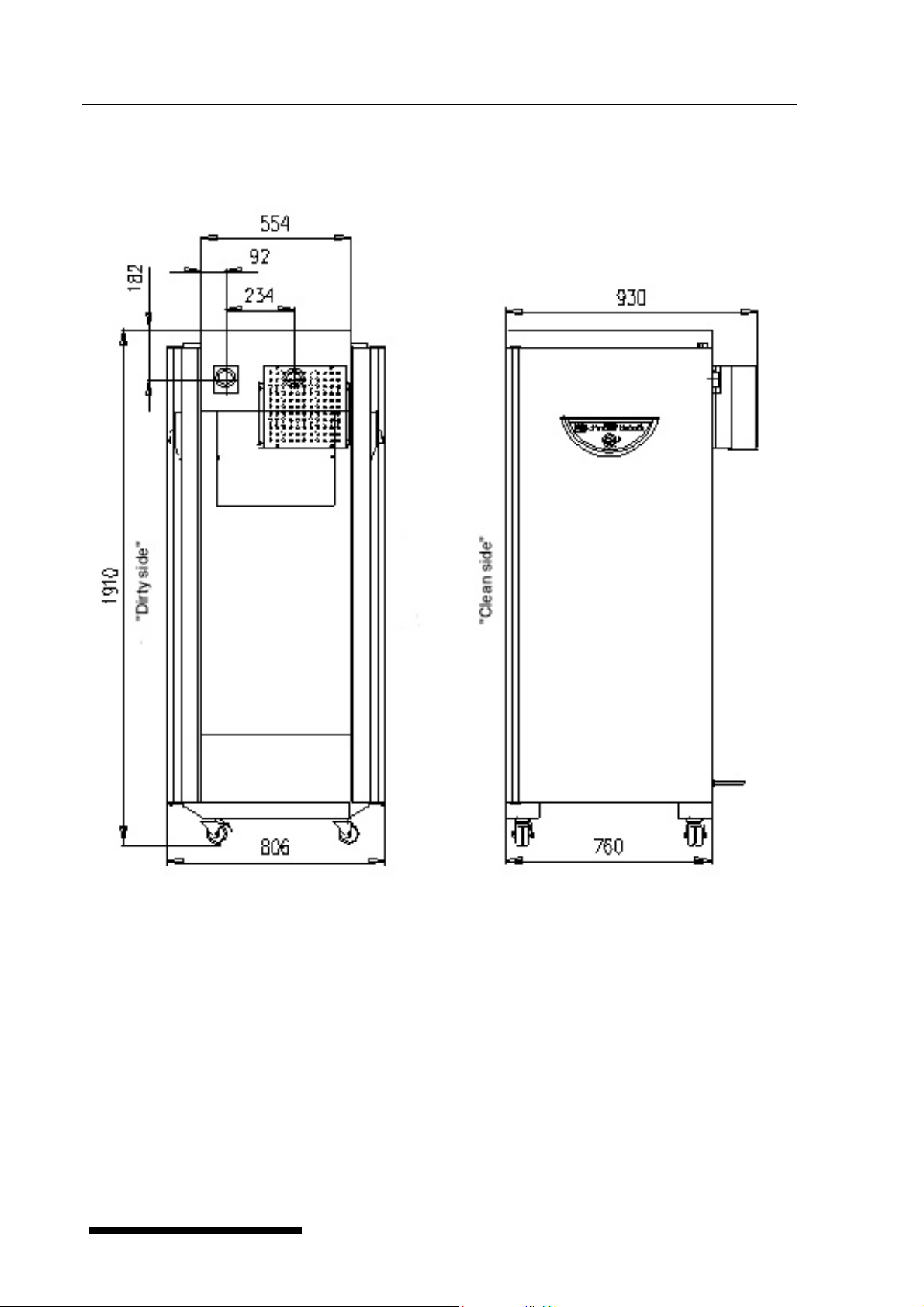
11.8.1 Two-door STERICELL 404 - installation data
1) input power 3700 W
2) electrical installation – connection of the device:
- plug VDE 0623, DIN 4962/63, CEE 17, IEC 309, 3P + N + PE, 16A/380-415 VAC
- supply to the socket from the switchboard 5x2.5 mm
16 A – place near the unit
- cable length 3 m
3) heat emission at 200 °C: 1900 W
4) weight: 150 kg
2
Cu, protection by circuit breaker
LSI_S_en_np 0402_mmm V 1.09 Blue Line
Operating instructions Ovens line Standard Page
Main dimensions of STERICELL 404 - passing through
26
V 1.09 Blue Line LSI_S_en_np 0402_mmm

Operating instructions Ovens line Standard Page
27
LSI_S_en_np 0402_mmm V 1.09 Blue Line

Operating instructions Ovens line Standard Page
Cover sheets
28
Detail A
6x screw ∅ 4x40 with countersink head with cross groove for fixing to a wall insert dowels
with a size of 8 to the wall
Detail B
19x screw for a metal sheet ∅3,9x9 with a half-round head and a cross groove necessary
to screw with cover sheets with holes of ∅3.2
Detail C
By beating the pins to the rectangular holes of the sheet borders secure them together.
V 1.09 Blue Line LSI_S_en_np 0402_mmm

Operating instructions Ovens line Standard Page
11.9 Adaptation against drying-up of cultivating mediums and tissue cultures
This mechanical and program adaptation reduces considerably the drying-up of cultivating
mediums and tissue cultures when using INCUCELL with ventilator. Basically there is
increased the chamber tightness, it is not possible to open the valves of air holes, there is a
humidity tray added, the ventilator is closed when the door is opened.
29
LSI_S_en_np 0402_mmm V 1.09 Blue Line
 Loading...