

Instructions for use
Cooling incubator with controlled humidity – EVO line
CLIMACELL
111, 222, 404, 707, 1212
CLIMACELL EVO_np_en_1401_mmm_V1.01

Congratulations on purchase of the new cooling incubator with controlled humidity which is an ideal option for applications in
which you need to maintain or regulate temperature and relative humidity inside of the chamber in various time modes. In case
of optional equipment purchase, it will also allow you to measure and control concentration of CO
2
in the chamber respectively
other gases, intensity of lighting in the visible light zone or UV.
The incubator control uses the newest hardware components and know how in the fi eld of regulation using Fuzzy – logics. The
whole control system arranges high precision of temperature regulation, regulation of humidity and possibly other items and so
it arranges higher reliability of the whole process.
The devices meet the technical and legislative requirements and they are constructed in compliance with relevant EN
standards. They are manufactured from high-quality materials using the newest technologies. Each individual unit passes a
thorough output control and it is tested by testing programs.
If you will follow these instructions, the device will become your reliable and powerful partner.
As from today, all these qualities are at your disposal.
This device is really easy to use, thanks to intuitive control with wizards, but anyway we do recommend you to carefully
read the Instructions for Use to be able to use in full all and any features of the device and to get to know all the information
necessary for its optimal use.

CONTENTS:
31. 1. 2014
1 PRODUCT NAME................................................................................................................................3
2 PURPOSE AND USE.........................................................................................................................3
2.1 B
ASIC CHARACTERISTICS.............................................................................................................................3
3 DEVICE DESCRIPTION.......................................................................................................................4
3.1 G
ENERAL VIEW OF CLIMACELL EVO 111, 222..................................................................................................4
3.2 GENERAL VIEW OF CLIMACELL EVO 404, 707.................................................................................................5
3.3 COMMUNICATION PANEL...............................................................................................................................6
3.4 C
ONTROL PANEL.........................................................................................................................................7
3.5 USEFUL SPACE..........................................................................................................................................7
4 TECHNICAL DATA I..........................................................................................................................8
4.1 GENERAL DATA..........................................................................................................................................8
4.2 ELECTRIC INSTALLATION AND OTHER CONDITIONS............................................................................................8
4.3 C
OMMUNICATION INTERFACE........................................................................................................................9
5 BASIC EQUIPMENT.............................................................................................................................9
6 ADDITIONAL EQUIPMENT..................................................................................................................9
6.1 I
NTERNAL LIGHTING.....................................................................................................................................9
6.2 BUSHINGS WITH DIAMETER 25, 50, 100 MM..................................................................................................10
6.3 MECHANIC LOCK OF THE DOOR.................................................................................................................10
6.4 E
LECTRIC LOCKING (BLOCKING) OF THE DOOR.............................................................................................10
6.5 DOOR HINGED ON THE LEFT.......................................................................................................................10
6.6 INDEPENDENT SENSOR PT 100..................................................................................................................10
6.7 COMMUNICATION SW (WARMCOMM 4) FOR PC WITH WINDOWS......................................................................10
6.8 P
OTENTIAL – FREE CONTACT FOR ALARM REPORTS.......................................................................................10
6.9 INNER SWITCHED SOCKET.........................................................................................................................10
6.10 EXPOSITION LIGHTING...............................................................................................................................11
6.10.1 E
XPOSITION LIGHTING IN DOORS................................................................................................................11
6.10.2 EXPOSITION LIGHTING ON RACKS................................................................................................................11
6.11 SENSORS FOR MEASURING THE INTENSITY OF UV AND VIS EXPOSITION LIGHT IN THE CHAMBER.........................11
6.12 TEMPERATURE RANGE FROM - 20 °C............................................................................................................11
6.13 CHAMBER DE-CONTAMINATION.....................................................................................................................11
6.14 R
EGULATION OF CO
2
CONCENTRATION.........................................................................................................11
6.15 COMMUNICATION MODULE WITH ETHERNET, WIFI, USB HOST.........................................................................11
6.16 PRINTER DPT - 6333...............................................................................................................................11
6.17 ANDROID APPLICATION FOR DEVICE STATUS MONITORING...........................................................................11
7 PUTTING THE DEVICE INTO OPERATION..................................................................................12
7.1 U
NPACKING AND CONTROL.........................................................................................................................12
7.2 IMPORTANT WARNINGS...............................................................................................................................12
7.3 DEVICE PLACEMENT..................................................................................................................................13
7.4 CONNECTION TO WATER SOURCE AND WASTE..............................................................................................13
7.5 C
ONNECTION TO DISTRIBUTION NETWORK...................................................................................................14
8 DEVICE STAFF..................................................................................................................................14
8.1 D
EVICE SWITCH-ON..................................................................................................................................14
8.2 BASIC MENU............................................................................................................................................14
8.3 DEVICE USER MENU.................................................................................................................................14
8.3.1 NATIONAL ENVIRONMENT............................................................................................................................15
8.3.2 USER ADMINISTRATION..............................................................................................................................15
8.3.2.1 W
ITHOUT USER ADMINISTRATION MODE......................................................................................................15

8.3.2.2 ADVANCED USER ADMINISTRATION................................................................................................................15
8.3.2.2.1 A
CTIVATING ADVANCED USER ADMINISTRATION................................................................................................16
8.3.2.2.2 CHANGING USER PASSWORD.......................................................................................................................17
8.3.2.2.3 LOGGING OUT............................................................................................................................................17
8.3.3 W
ARNINGS AND ERRORS..............................................................................................................................17
8.3.3.1 CURRENT ERROR MESSAGES........................................................................................................................17
8.3.3.2 HISTORY OF FAULTS....................................................................................................................................18
8.3.4 DISPLAY AND SOUNDS.................................................................................................................................18
8.3.5 DEVICE MAINTENANCE MENU........................................................................................................................19
8.3.5.1 S
INGLE DEFROSTING....................................................................................................................................19
8.3.5.2 DECONTAMINATION.................................................................................................................................19
8.3.5.3 DRYING...............................................................................................................................................20
8.3.6 C
URRENT DATE AND TIME SETTING..............................................................................................................20
8.3.7 COMMUNICATION – ACTIVATION......................................................................................................................21
8.3.7.1 WIFI CONNECTION ACTIVATION......................................................................................................................21
8.3.7.2 E-MAIL ACCOUNT ACTIVATION........................................................................................................................22
8.3.7.3 WIFI CONNECTION VIA INTERNET BROWSER.................................................................................................22
8.3.8 PRINT..............................................................................................................................................23
8.3.8.1 P
ROTOCOL PRINTING...................................................................................................................................24
8.3.9 B
ACKUP...................................................................................................................................24
8.3.10 S
ERVICE SETTING.......................................................................................................................................24
8.3.10.1 C
OMMUNICATION – SETTINGS.........................................................................................................................24
8.3.10.1.1 ETHERNET SETTING.....................................................................................................................................25
8.3.10.1.2 WIFI SETTING............................................................................................................................................25
8.3.10.1.3 E-MAIL SETTING.........................................................................................................................................26
8.3.10.2 TOUCH PANEL CORRECTION.........................................................................................................................26
8.3.10.3 U
NITS...........................................................................................................................................26
8.3.10.4 RACK..............................................................................................................................................27
8.3.10.5 AUDIT TRAIL..............................................................................................................................................27
8.3.10.6 OVERVIEW OF INPUTS AND OUTPUTS............................................................................................................28
8.3.10.6.1 A
NALOGUE ITEMS.......................................................................................................................................28
8.3.10.6.2 DIGITAL INPUTS AND OUTPUTS.....................................................................................................................28
8.3.11 TESTS................................................................................................................................................28
8.3.11.1 C
OOLING TEST...........................................................................................................................................28
8.4 PROGRAMS.....................................................................................................................................29
8.4.1 LIST OF PROGRAMS.....................................................................................................................................29
8.4.2 DEFINITION OF PROGRAM.............................................................................................................................29
8.4.2.1 SAFETY THERMOSTAT...................................................................................................................................29
8.4.3 P
ROGRAM CONFIGURATION...........................................................................................................................30
8.4.4 SEGMENT SETTINGS....................................................................................................................................31
8.4.4.1 SETTING OF PROGRAMS WITH LIGHT EXPOSITIONÍ..........................................................................................31
8.4.4.2 ALARMS........................................................................................................................................32
8.4.5 TEMPERATURE AND RELATIVE HUMIDITY SETTING AND THEIR LIMITATIONS...............................................................32
8.4.6 P
ROGRAM START MENU..............................................................................................................................33
8.4.7 PROGRAM START........................................................................................................................................33
8.4.7.1 RUNNING PROGRAM GRAPH........................................................................................................................34
8.4.7.2 RUNNING THE PROGRAM WITH LIGHT EXPOSITION............................................................................................34
8.4.7.3 POSTPONED START OF PROGRAM..................................................................................................................34
8.4.7.4 D
OOR OPENING..........................................................................................................................................35
8.4.7.5 DOOR BLOCKING.........................................................................................................................................35
8.4.7.5.1 DOOR BLOCKING IN THE MODE WITHOUT USERS ADMINISTRATION......................................................................35
8.4.7.5.2 D
OOR BLOCKING IN THE MODE OF ADVANCED USERS ADMINISTRATION...............................................................36
8.4.7.6 CURRENTLY RUNNING PROGRAM EDITING.......................................................................................................36
8.4.7.7 POWER SUPPLY OUTAGE..............................................................................................................................37
8.5 HISTORY OF PROTOCOLS..............................................................................................................................37
8.6 SYSTEM INFORMATION.................................................................................................................................38

9 LIST OF ERROR MESSAGES........................................................................................................39
10 DEVICE MAINTENANCE.....................................................................................................................41
10.1 M
AINTENANCE PLAN....................................................................................................................................41
10.2 D
OOR SEALING REPLACEMENT......................................................................................................................42
10.3 DOOR ADJUSTMENT.....................................................................................................................................42
10.4 ACCUMULATION OF CONDENSED WATER STEAM..............................................................................................43
10.5 DEVICE CLEANING AND DECONTAMINATION.....................................................................................................43
10.6 STEAM GENERATOR....................................................................................................................................44
10.7 R
EVISION OF ELECTRO PART S......................................................................................................................44
11 TECHNICAL DATA II.........................................................................................................................45
11.1 O
PERATION D ATA........................................................................................................................................45
11.2 RACKS WITH EXPOSITION LIGHTING............................................................................................................46
12 WARRANTY AND SERVICE...............................................................................................................47
13 TRANSPORT AND STORAGE...........................................................................................................47
14 WAY OF LIQUIDATION.......................................................................................................................47

1 PRODUCT NAME
The Instructions for use apply to the below stated device
models:
Type Model Trade Name ZP Type Construction
Design
CLC - E CLC kkk-c CLIMACELL - Evo automatics –
touch screen
E – EVO (Evolution)
kkk – chamber size 111, 222, 404, 707, 1212
c – cooling up to -20 °C.
2 PURPOSE AND USE
The device CLIMACELL EVO is designed for applications
requiring precise and reproducible simulation of variable
climatic conditions. In its basic version, the incubator allows
simultaneous regulation of temperature and humidity. In
case of additional equipment purchase it offers regulations
of concentration of CO
2
respectively other gases or space
– homogenous lighting in the fi eld of visible or UV light with
adjustable intensity and possibility of intensity measuring
using special sensors. Thanks to the unique combination
the device offers the user with extensive possibilities of use.
CLIMACELL EVO can be used in biology, food processing
industry, chemical industry, electrical technology, histology,
botany, pharmacy and others. A typical example may be the
cultivation of plant and tissue cultures or tests of stability
(photo stability) of materials and medicaments.
2.1 BASIC CHARACTERISTICS
● In the operation space of the device it is possible to
simulate the environment with temperature 0 up to
100 °C (-20 °C up to 100 °C for model „c“), relative
humidity (hereinafter referred to as RH) 10 % up to
95 %. For possible combinations of temperature and RH
see chapter 8.4.5 .
● Possibility of chamber decontamination / sterilization at
160 °C.(this function is not designed for sterilisation of
samples or material).
● Control of space – homogenous lighting with wave
length in visible and UV zone. The light exposition may
be monitored using optional sensors.
● Regulation of CO
2
in the range from 0 up to 20 %
(0-2000 ppm), max. temperature 55 °C. (respectively of
other gases).
● Temperature, RH, lighting and concentration of CO
2
(respectively of other gases) may be regulated in various
time modes.
● Tested samples are stored on racks supplied together
with the device.
● The unique system of air circulation with forced
circulation guarantees space – homogenous distribution
of temperature and RH in the whole operation space of
the device.
● Set speeed of fan from 0 to 100 % in ten – percent
intervals.
● The chamber and all the inner parts are made of
stainless steel. The outer shell is made partially of
zinc-coated and stainless steel material and it is treated
with water-soluble stove enamel (environment - friendly).
● CLIMACELL EVO is equipped with a multi-processor
control with the following characteristics:
o Precise regulation of temperature, humidity, lighting
and CO
2
(gas) with application of the newest trends
in the fi eld of regulation (fuzzy logic), supported by
many years of experience of the company BMT in
this fi eld.
o Graphic display with touch panel allows simple and
intuitive control.
o Wide offer of communication interfaces - Ethernet,
Wifi , USB, RS232. – according to optional equipment
o As many as 100 freely adjustable programs.
Each program may consist from up to 100 partial
segments.
o Possibility of structuring the users into groups with
differentiated access rights to the operation and
service settings of the device.
o In internal memory of the device there is
automatically saved the record of the course
of regulation including audit trail, total length of
recording up to one year.
o The user has the possibility to make backup of some
device settings and record of the regulation on the
SDHC card, fl ash disc or some other large-capacity
memory USB device.
o Support of WarmComm4 software for regulation
progress recording.
Instructions for use
CLIMACELL EVO_np_en_1401_mmm_V1.01 3
Instructions for use
4 CLIMACELL EVO_np_en_1401_mmm_V1.01
3 DEVICE DESCRIPTION
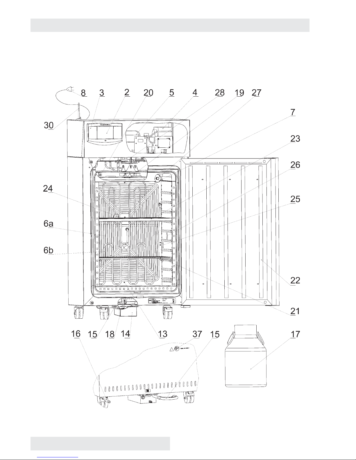
3.1 GENERAL VIEW OF CLIMACELL EVO 111, 222
Fig. 1
Instructions for use
CLIMACELL EVO_np_en_1401_mmm_V1.01 5
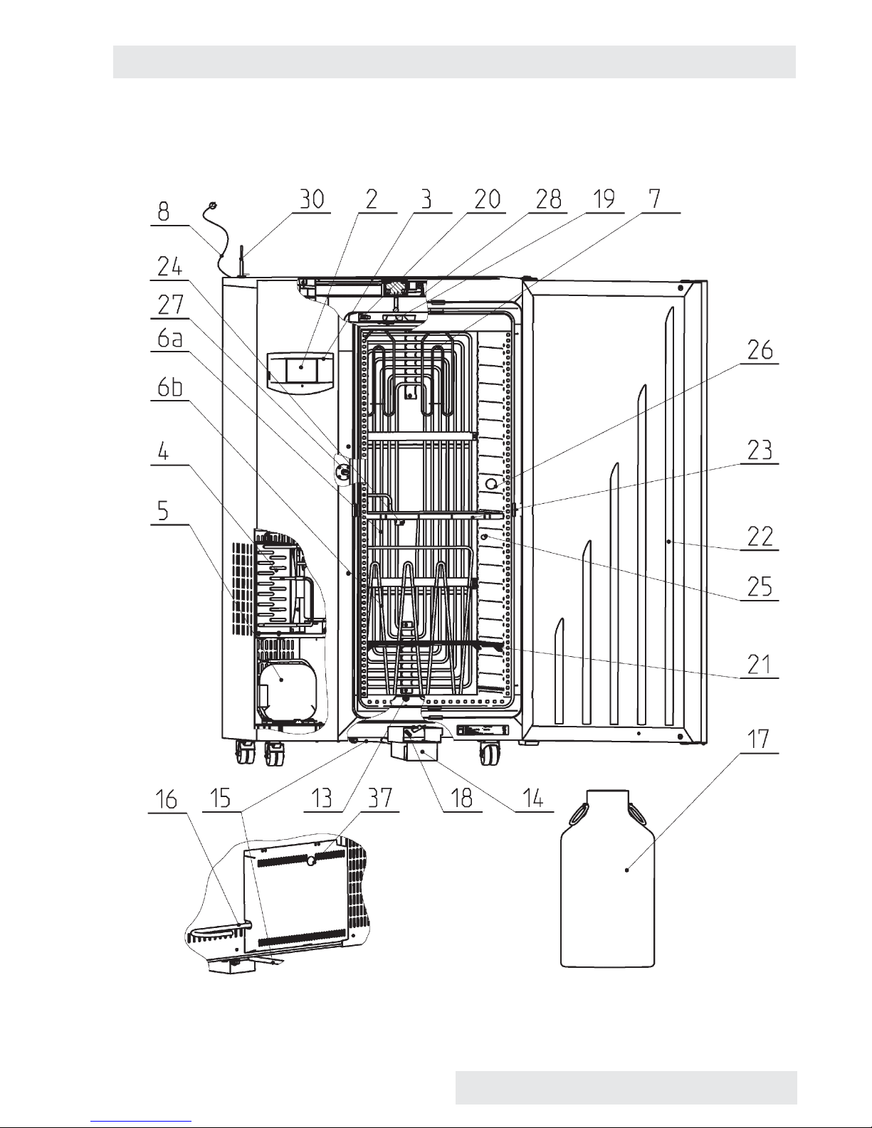
3.2 GENERAL VIEW OF CLIMACELL EVO 404, 707
Fig. 2
6 CLIMACELL EVO_np_en_1401_mmm_V1.01
Instructions for use
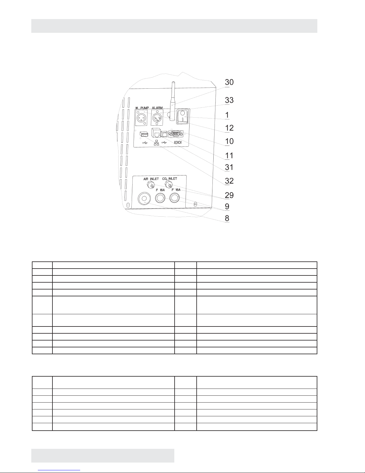
3.3 COMMUNICATION PANEL
Fig. 3
Standard version
1 Network push button 12 Pump connector
2 Control touch panel 13 Input of steam from steam generator
3 Plastic cover of control panel 14 Waste vessel with pump
4 Condenser 15 Waste water discharge
5 Compressor 16 Water inlet from reservoir
6 Cooling tube evaporator -
6a - cooling,
6b - freezing (RH regulation)
17 Distilled water reservoir
7 Heating bodies in heating space 18 Outlet of waste water from chamber and door to the
vessel
8 Network connection 19 Temperature sensor PT 100
9 Fuses T16A/1500 20 Relative humidity sensor
10 Connector RS232 21 Screens (2 pcs)
11 Connector USB device (USB B)
Optional equipment
22 Exposition lighting in the door (LED, fl uorescent
lamps)
29 Inlet of CO2 (gas) and air (external)
23 Exposition lighting of racks ( LED, fl uorescent lamps) 30 Wifi antenna
24 Lighting sensor (VIS or UV) 31 LAN connector
25 Placement inside of switched socket 32 Connector USB HOST
26 Placement of inner bushing 33 Potential-free contact
27 Sensor of CO
2
(gas) 37 Outlet of steam prom pressure safety lock
28 Inlet of CO2 (gas) to the chamber (internal)
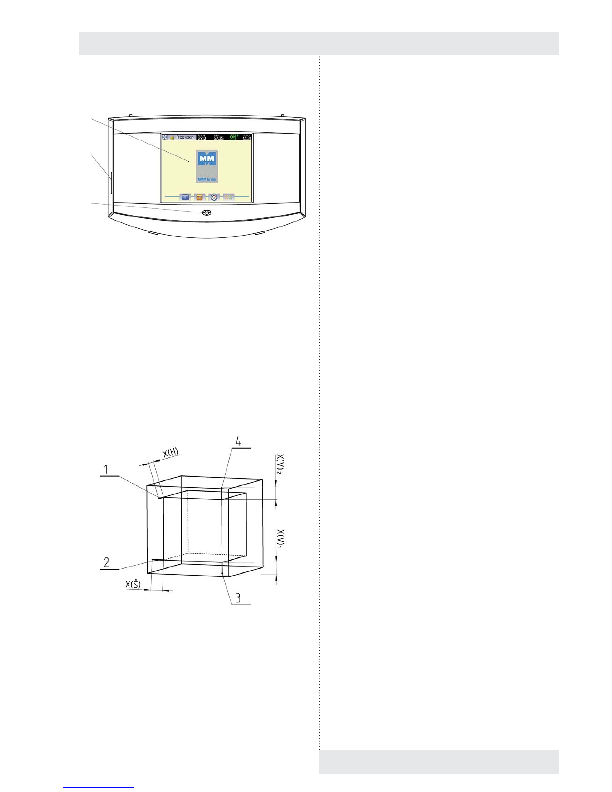
3.4 CONTROL PANEL
Fig. 4
(1) Control touch panel
(2) SD card
(3) Indication LED
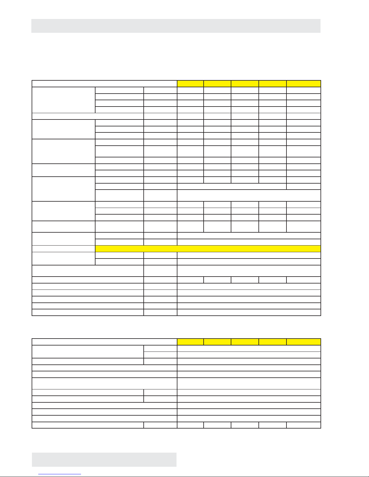
3.5 USEFUL SPACE
Useful space is displayed in Fig. 5. In the space delimited
with thick lines in the fi gure there are fulfi lled (in connection
with standard DIN 12 880) the temperature variations as
specifi ed in chapter 11. The thin lines demark inner walls of
the chamber. That means that above the last upper screen,
the values from this chapter are not binding any more.
Fig. 5
(1) X(H) – 10 % of inner chamber depth
(2) X(Š) – 10 % of inner chamber width
(3) X(V)1 – distance of the lowest screen (rack) from the
bottom of the inner chamber
(4) X(V)2 – distance of the top screen (rack) from the
ceiling of the inner chamber
CLIMACELL EVO_np_en_1401_mmm_V1.01 7
Instructions for use
1
2
3
8 CLIMACELL EVO_np_en_1401_mmm_V1.01
Instructions for use
4 TECHNICAL DAT A I
4.1 GENERAL DATA
Name CLIMACELL E 111 / 111-c 222 / 222-c 404 / 404-c 707 / 707-c 1212 / 1212-c
Inner space of the chamber,
stainless steel DIN 1.4301
(AISI 304)
Volume approx. litre 110 219 404 704 1408
Width mm 540 540 540 940 3x540 (1905)
Height mm 535 765 1415 1415 1415
Depth mm 380 530 530 530 530
Steam space volume approx. litre 167 305 530 878 1753
Outer dimensions (including
door, handrail and wheels)
Width mm 780 780 1100 1500 2530
Height mm 1215 1450 1880 1880 1915
Depth mm 755 885 885 885 885
Dimensions with package
(three-layer cartoon)
Width mm 850 850 1170 1570 2600
Height (including
palette)
mm 1360 1630 2070 2070 2105
Depth mm 840 980 950 950 950
Weight net kg 110/120 /153 240/250 280/290
gross kg 140/150 /172 280/290 326/336
Screens
of stainless steel *)
Lead for screens max. No. 7 10 19 19 3x 19
Standard equipment pc 2 6
Pitch between
screens
mm 70
Maximal load Screen kg/screen 20 30 30 50 30
Sheet rack kg/rack 20 30 30 20 30
In total kg/case 50 70 100 130 300
Number of doors External - metal/
internal – glass
pc 1 / 1 1 / 1 1 / 1 2 / 2 3/3
Min. distance of the device
from the walls and objects
Rear and side walls mm 200
Upper wall mm 400
Steam generator connection It is prohibited to use tap water!
Demi water Usual μS/cm ˂ 8
Recommended μS/cm ˂ 3
Pressure from the distribution system for central
distribution
bar ≤ 0,5
Water cask volume litres 20 20 50 50 50
Min. height of water level in cask mm 25
Max. pumping height of waste water mm 1150
Pump cable length mm 4000
Suction hose length mm 4000
Waste hose length mm 4000
4.2 ELECTRIC INSTALLATION AND OTHER CONDITIONS
Electric installation and other conditions 111 / 111-c 222 / 222-c 404 / 404-c 707 / 707-c 1212 / 1212-c
Voltage system standard 1x 230V/ 50(60) Hz
opce 1x 115V/ 50(60) Hz
Network voltage oscillation % ± 10
Class of protection against dangerous touch I
Separation of external circuits Double insulation
Device for type standard CEE-7/VII, IEC-83/CH,16 A/250 V (or other depending on
version)
Intake cable length mm 3000
Socket protection A min. 16
Coverage according to EN 60529 IP 20
Overvoltage category according to (IEC 664 – EN 61010) II with pollution 2
Fuses on rear wall of the superstructure (extension) Safety fuse T 16A/1500
Max. input of the device **) W 2050/1630 2100/1780 3150/2115 3400/2640 xx/3215
Heat losses at 37 °C ca W 70 63 123 148 200
Complete device noise level dB 46 50/56 56/58 58 60
Operation conditions Let the installed device stand still in operation position for 2 hours before its fi rst put
into operation!
Ambient temperature °C +5 up to +40
Max. relative humidity at 31 °C % RH 80
Max. height above sea level m n. m. 3000
4.3 COMMUNICATION INTERFACE
● Ethernet: 10/100 Mbps
interface 1 x RJ45
standard IEEE 802.3u
half/full duplex
● Wifi : IEEE 802.11b, IEEE 802.11g
Frequency:
Europe: 2.412-2.472GHz
USA: 2.412-2.462GHz
Japan: 2.412–2.484GHz
Channels:
Europe: 13 channels
USA: 11 channels
Japan: 14 channels
● USB host: USB 2.0, full speed
● USB device: USB 2.0, full speed
● SD/MMC card: max. capacity 32 GB
● RS232:
- Printer connection:
Baud: 9600
Stopbit: 1
Parita: none
Databit: 8
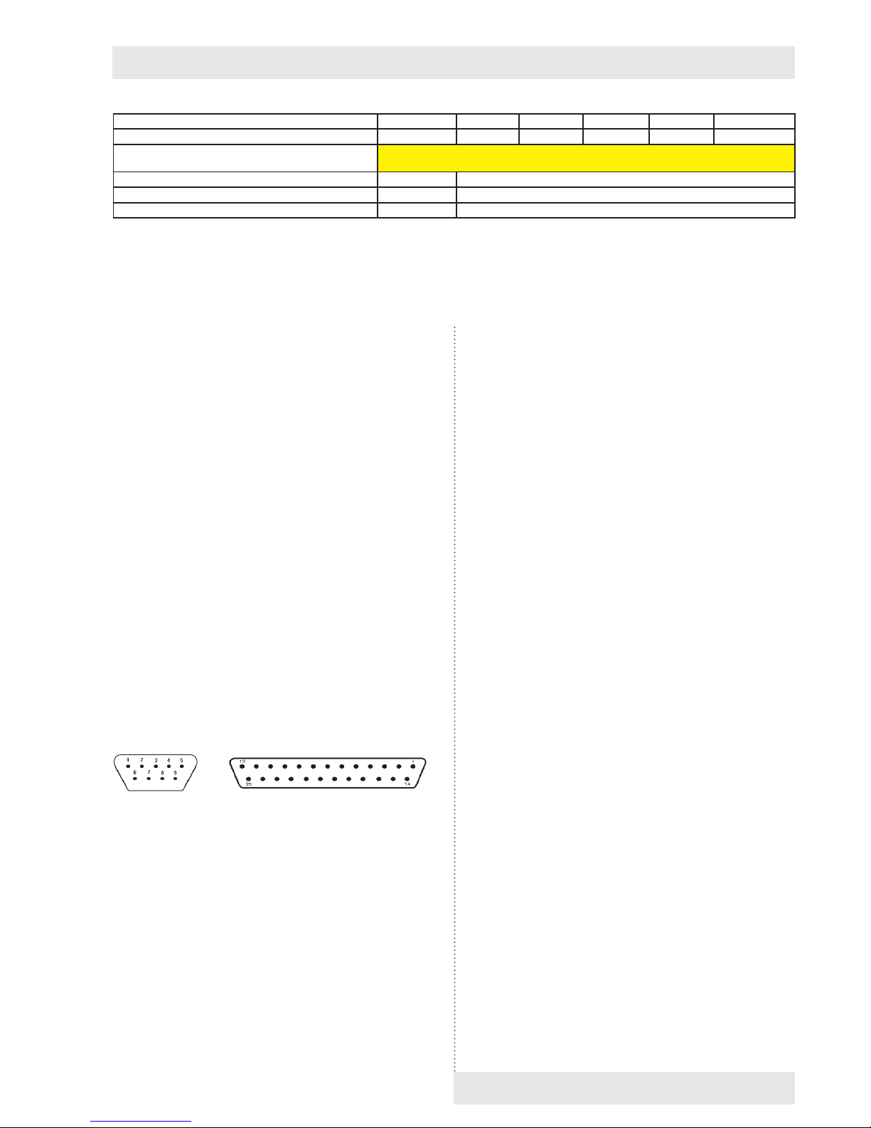
Device Printer
Fig. 6
9 pin Canon connector on box DE9 Male
Pin Signal
2 RXD
3 TXD
4 DTR
5 GND
6 DSR
25 Canon connector on printer DB25 Female
Pin Signal
2 TXD
3 RXD
7 GND
20 DTR
Note:
Ethernet, Wifi and USB Host ara available only with devices
with communication module, see chapter 6.15.
5 BASIC EQUIPMENT
The standard supply includes:
● incubator,
● two screens,
● fi lling system (order No. S211567 or S211568),
● waste system (order No. S211558),
● handling hooks (only size 404 and 707),
● instructions for incubator use,
● SD card.
6 ADDITIONAL
EQUIPMENT
6.1 INTERNAL LIGHTING
The lights are placed inside of the chamber on the left. Heatresistant bulbs are used. The light switch is placed on the
door. In combination with the door window there is always
a light placed in the door.
CLIMACELL EVO_np_en_1401_mmm_V1.01 9
Instructions for use
All the data apply in empty chamber (without samples on screens) for ambient temperature of 20 - 22 °C, 100 % fan revolutions,
feeding voltage 230 V ± 10 %.
*) The screens may be fi lled in approximately 50 % of surface and if possible in such a way so as there is allowed equal air
fl ow inside of the chamber space.
**) Compressor + condenser + electromagnetic valves + fan(s) + steam generator heating.
6.7 COMMUNICATION SW
(WARMCOMM 4) FOR PC WITH
WINDOWS
The program WarmComm is designed for recording of the
temperature regulation course in temperature cases. The
data obtained in the course of regulation are displayed
in the form of a graph. The program allows monitoring of
regulation in real time, saving of the regulation progress in a
fi le, watching formerly created fi les, sending e-mails in case
of non-receiving data from the case and sending reports on
extreme values reached in a set time interval.
Instructions for use of the program are supplied together
with the installation program. The hardware requirements
can be managed by a standard PC with operation system
Windows XP or higher.
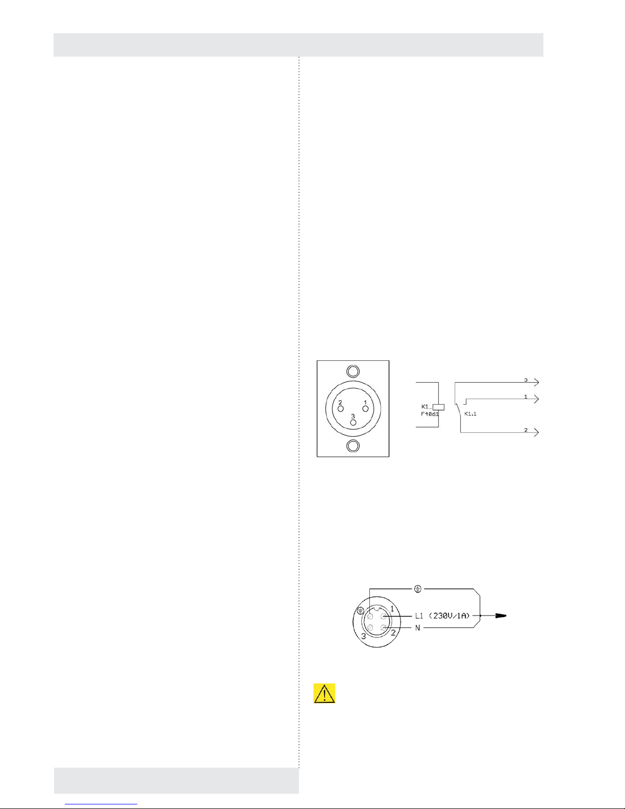
6.8 POTENTIAL – FREE CONTACT
FOR ALARM REPORTS
It is taken out to the connector (33), Fig. 3, in the rear part
of the device. Maximal load of the contact: 24V/1A..
Fig. 7
6.9 INNER SWITCHED SOCKET
The socket (nominal voltage 230V, fuse 3 A, coverage IP67)
is located inside of the chamber on the side wall. For details
on switching control see chapter 8.4.3.
Connection of the connector and the built-in device
Fig. 8
The fork may be connected only by a person with
relevant electro technical qualifi cation. When inserting the
fork to the socket and pulling the socket out of the socket or
when handling the inner equipment, it is necessary for the
device to be switched off (network switch in the off position
10 CLIMACELL EVO_np_en_1401_mmm_V1.01
Instructions for use
6.2 BUSHINGS WITH DIAMETER 25,
50, 100
MM
Standard placement of bushings can be found
approximately in the centre of the side (left or right) wall
of the chamber. The bushings are made of metal, they
are closed from the outer side with a special plastic plug
allowing lacing the conductors etc. from the outer space to
the chamber space.
Recommendation: the device used should be equipped with
a dimension-corresponding bushing in case that the user
wants to measure one of the items (T, RH, CO
2
, etc.) with
sensors connected with the external independent measuring
device by conductors; the user pulls the conductors through
the bushing. So as to reach the correct functioning of the
incubator, the conductors, hoses, etc. pulled through the
bushing must be hermetically sealed in the bushing.
6.3 MECHANIC LOCK OF THE DOOR
The lock is placed on the upper front surface of the door
close to the locking mechanism.
6.4 ELECTRIC LOCKING (BLOCKING)
OF THE DOOR
In the course of the material exposition, the door is
blocked by an electromagnetic mechanism so as to avoid
undesirable opening.
6.5 DOOR HINGED ON THE LEFT
This is a mirror-like symmetrical version of the door hinged
on the right. Cases with volumes of 404, 707 and 1212 litres
are not supplied in left version.
6.6 INDEPENDENT SENSOR PT 100
The independent movable sensor is used for measuring the
material temperature directly in the chamber. It is possible to
connect as many as four sensors.
The data on temperature of the sensors are displayed in
system information, see chapter 8.6.
When printing on the printer, each record consists of a
few lines, the fi rst line starting with number 1 shows the
temperature on the regulator sensor, the other lines starting
with letters display the temperature on movable sensors.
Fork
To the device

6.13 CHAMBER DE-CONTAMINATION
The chamber is heated to 160 °C and the temperature is
kept for specifi ed time period. Everything is controlled by the
given program and it is not possible to change the values.
6.14 REGULATION OF CO2
CONCENTRATION
Using the regulation system and the CO2 sensor it is
possible to correct and measure the CO
2
concentration in
the chamber. Allowed temperature range is from -20 °C
to 60 °C, the humidity is not limited, but water must not
condensate on the sensor. The range of CO
2
concentration
is from 0 to 20 % or 0-2000 ppm respectively it may also be
different – it depends on the CO
2
sensor type used and on
device confi guration by the manufacturer.
6.15 COMMUNICATION MODULE WITH
ETHERNET, WIFI, USB HOST
● The communication module allows connection of the
device to local network using LAN connector or Wifi .
● It provides an active web server accessible via LAN.
The web server allows remote monitoring of current
regulation progress on the device, viewing the history of
protocols and audit trail.
● It is possible to use the communication module for
sending e-mails in case of error status occurrence or in
case of any warning.
● It provides the user with communication interface USB
host, via which it is possible to connect USB fl ash disk
respectively some other large capacity memory device
doer data saving.
6.16 PRINTER DPT- 6333
The thermo printer connectible via RS232, paper width
58 mm, is supplied with a cable and feeding source.
6.17 ANDROID APPLICATION FOR
DEVICE STATUS MONITORING
The CLC Monitor application is designed for monitoring
of device activity at mobile devices with operation system
Android. The application provides the user with information
on current status of remote device within the reach of WIFI.
CLIMACELL EVO_np_en_1401_mmm_V1.01 11
Instructions for use
– „0“). The connection socket – fork must be appropriately
tightened so as not to decrease the declared degree of
protection (IP 67). After disconnection of the fork and the
socket carefully screw the protection covers on the socket
and the fork so as impurities and humidity cannot penetrate
into them.
Note:
In this version, the maximal operation temperature of the
device is limited to 60 °C.
6.10 EXPOSITION LIGHTING
6.10.1 EXPOSITION LIGHTING IN DOORS
The exposition fl uorescent or LED lighting is placed in the
door. Its intensity is controlled from 0 % to 100 % in steps of
10 %, see chapter 8.4.4.
6.10.2 EXPOSITION LIGHTING ON RACKS
The chamber may house racks with exposition fl uorescent
or LED lighting, its intensity is controlled from 0 % to 100 %
in steps of 10 %, see chapter 8.4.4.
6.11 SENSORS FOR MEASURING
THE INTENSITY OF UV AND
VIS EXPOSITION LIGHT IN THE
CHAMBER
The measured values may be displayed on the display
and they are saved in the program protocol. Both types of
sensors may be simultaneously used in one device (six
sensors as a maximum).
Notes:
Sensors for measuring the intensity of UV and VIS light
have the range of operation temperature from -20 °C to
80 °C. So as to avoid their damage, the temperature in the
chamber is limited as follows:
o maximal operation temperature of the device is limited to
75 °C,
o in case of the temperature in the chamber to reach
80 °C, all the heating elements and exposition lighting is
switched off and an alarm is announced.
6.12 TEMPERATURE RANGE FROM -
20 °C
The RH is not regulated in the temperature range from
-20 °C to +10 °C.
This version cannot be combined with exposition lighting on
the door (in switched on and off status) and on the racks (in
switched on status).
Instructions for use
12 CLIMACELL EVO_np_en_1401_mmm_V1.01
The devices are not designed for environment
with risk of fl ammable or explosive substances
(e.g. anaesthetics).
If the device is used with CO2, it is necessary to
protect the premises in case of excessive gas
leakage (well ventilated room, sensors of CO
2
with alarm, etc.).
Any assemblage or disassembly of parts of the
device may only be performed after the device
disconnection from electric network by pulling
the feeding cable from the socket!
In case of temperatures below 0 °C or above
60 °C there is a risk of injury caused by metal
handles on inner glass doors. Use protective
aids.
When operating a device with pre-set
temperature above 70 °C be extremely careful
when opening the door. As the pre-set RH is kept,
hot steam develops in the chamber and it may
cause scalding.
The protection of the temperature case, its
surroundings and processed material against
prohibited temperature exceeding is arranged by a
protective thermostat according to EN 61010-2-010.
The network connection must not get in touch with
hot parts of the device.
You can fi nd all and any installation conditions of the
device in tables, see chapter 4.
The cases stand on the fl oor, they are space saving,
equipped with castor wheels. It is necessary for the
cooling incubator to stand on fl at fl oor (because of
the device functionality). And we recommend a waste
canal to be located in the room for any case of water
leakage.
After the device placement to the desired location,
turn and set the brake of the castor wheels. The front
one in the front direction and the rear ones in the rear
direction, in parallel with sides of the device in such a
way so as the device gets maximal possible stability
in forward and backward directions.“
Always place the material on screens in the device,
never put it on the bottom of the device!
If you want to start the chamber decontamination, it
must be empty (only the RH sensor may stay).
7 PUTTING THE
DEVICE INTO
OPERATION
7.1 UNPACKING AND CONTROL
After unpacking please check whether the device and its
accessories are complete and undamaged.
Any possible damage must be immediately reported
to the carrier! Do not lift up the case for the handrail or
door in the course of handling (e.g. case lifting, etc.). Lift
the case up using the enclosed hooks. When removing the
case from the palette take care of the device bottom. Lift the
case up using the hooks and move the palette completely
out. Then put the case carefully on the wheels designed for
local movements on smooth fl oor – not for any prolonged
transport. Pay attention mainly to door steps and entries
to lifts. In such cases it is also necessary to lift the case up
using the hooks. In the course of any handling of the case,
the door must be closed and the case must be disconnected
from power mains. When moving the case be always very
careful and handle the case in such a way so as not tip it
over. In case of sizes 404, 707 and 1212 it is necessary to
protect the case against possible tipping over by fastening it
to the wall see chapter 7.3.
7.2 IMPORTANT WARNINGS
CLIMACELL is designed and manufactured in compliance
with requirements of EU regulations No. 2006/95/EC and
2004/108/EC and it is individually tested according to
EN 61010-1.
Let the installed device stand still in operation position
for at least two hours before putting it into operation for
the fi rst time.
Read these Instructions for Use carefully before
starting the use of the device!
The load capacity of the fl oor for the device
placement must correspond with the weight of
the device, taking into consideration the maximal
charge weight (see chapter 4.1).
It is not allowed to place the device on a mat that
may cause a risk of fi re or smouldering in case of
hot objects to fall out of the device.
It is not allowed to insert any fl ammable,
explosive or poisonous substances or materials
that could release such substances to the device!
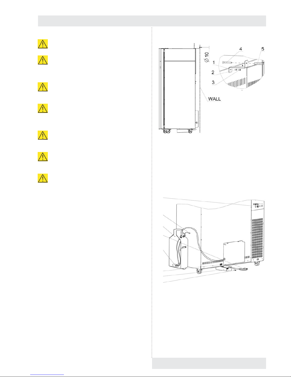
Fig. 9
7.4 CONNECTION TO WATER
SOURCE AND WASTE
The device may be connected to the cask supplied by us
or to water distribution system. In both case, the water and
water mains must meet the parameters as per chapter 4.1.
Fig. 10
a) Take the cask (1) out of the chamber.
b) Connect the cable connector (3) to the socket (4) back
on the superstructure, see chapter 3.3.
c) The waste vessel (5) is placed in the chamber. After
unpacking, insert it to the holder above the device.
Connect the cable connector (6) to the socket (7).
Connect the free end of the waste hose (8) to the
discharge.
Instructions for use
CLIMACELL EVO_np_en_1401_mmm_V1.01 13
It is not possible to start decontamination in devices
with a window in the door.
The temperature and RH regulation is negatively
affected by reduction of fan speed, exposition lighting
and measuring of CO
2
. There do not apply the values
from chapter 11.1.
The RH regulation is also negatively affected in case
of any other humidity source but the generator to be
in the chamber.
If you use the device for long-term several days
lasting tests at low temperatures, the ice in the
chamber will grow up similarly to a refrigerator or a
freezer.
Devices connected via communication interface
must meet valid regulations from the point of view of
electrical safety and electromagnetic compatibility.
If you do not use the incubator for prolonged time,
disconnect it from the network by pulling the feeding
cable form the socket.
In case of the device to be used in any other but
designed way, the protection provided by the device
may be affected.
7.3 DEVICE PLACEMENT
Cases with volumes of 404, 707 and 1212 l must be fi xed to
the wall in the room using the enclosed fi xation set. Place
the device to the required location and mark the place for
drilling a hole in the wall. Drill the hole according to the wall
plug used. The wall plug supplied is designed for ordinary
bricks – in case of any special bricks it is necessary to use
corresponding wall plug type.
a) Drill a hole to a fi xed wall and place the wall plug into it
(5).
b) Fix the fi xation set (1), (2), (3) on the device.
c) Fasten the device to the wall using the enclosed screw
(4).
4
3
1
8
2
7
5
6

Fig. 11
d) Pull the hose from the generator (P1) through the
bushing in the cask and apply the submersible pump (2),
(P2). Then tighten the bushing in such a way so as the
hose (P3) is sealed.
e) Fill the cask with distilled water and the device is ready
for operation.
Note:
It is not allowed to prevent fl ow of let-in and let-out water in
hoses.
7.5 CONNECTION TO DISTRIBUTION
NETWORK
Compare the nominal voltage and device input values
as specifi ed in the production plate of the device with the
voltage intake. If the intake parameters correspond with the
device parameters, connect the fork of the device to the
intake socket.
8 DEVICE STAFF
8.1 DEVICE SWITCH-ON
After switching the network switch (1), Fig. 3, to position „I“
the display of the control panel displays the basic menu of
the device. The indication LED (3), Fig. 4 lights green.
Instructions for use
14 CLIMACELL EVO_np_en_1401_mmm_V1.01
(1) (2) (3) (4)
(5) (6) (7) (8) (9) (10) (11) (12)
(13)
8.2 BASIC MENU
Fig. 12
(1) Programs (8.4).
(2) Protocol history (8.5).
(3) System information (8.6).
(4) Device user menu (8.3).
(5) Help.
(6) User login icon (8.3.2).
(7) Name of logged-in user
(8) Current temperature in the working part of the device.
(9) Current relative humidity (RH) in the working part of
the device.
(10) Warning and error indication (8.3.3.1).
(11) Device status information (8.4.7).
(12) Current date and time.
(13) Device identifi cation number (8.3.7).
8.3 DEVICE USER MENU
In order for the device to be operated precisely as the user
requires, it must fi rst be set up. Click
(Fig. 12) to
open the device settings screen.
Note:
Only colour-highlighted icons may be used for user
settings; the grey icons are inactive (only accessible by the
administrator).

Instructions for use
CLIMACELL EVO_np_en_1401_mmm_V1.01 15
Fig. 13
(1) Selection of national environment (8.3.1)
(2) Error and report history (8.3.3.2)
(3) Display and sounds (8.3.4)
(4) User administration (8.3.2)
(5) Device maintenance (8.3.5)
(6) Date and time (8.3.6)
(7) Communication (8.3.7)
(8) Print (8.3.8)
(9) Backup (8.3.9)
(10) User administration (8.3.2)
(11) System tests (8.3.11)
(12) Service and system settings (8.3.10).
8.3.1 NATIONAL ENVIRONMENT
By clicking on the icon (Fig. 13) you will open the
menu for national environment selection.
Fig. 14
8.3.2 USER ADMINISTRATION
→
The device controls can be accessed in two different modes:
● Without user administration
See 8.3.2.1.
● With advanced user administration
See 8.3.2.2.
8.3.2.1 WITHOUT USER ADMINISTRATION
MODE
This mode is the factory default setting. The user has
access to all the device’s menus with the exception of
special service functions. This mode is particularly suitable
for users who do not require the device to be secured
against unauthorised access. It is not necessary to log in to
control the device.
The without user administration mode recognises two
different types of users:
● Free user:
o User with unrestricted access to the device controls
(except for special service functions).
o The fi eld (7), Fig. 12, displays the words free user.
● Administrator:
o May activate (deactivate) advanced user
administration, see 8.3.2.2.
o The fi eld (7), Fig. 12 displays the word admin.
8.3.2.2 ADVANCED USER ADMINISTRATION
Allows the user structure to be defi ned with different rights
for access to controls and device settings.
Advanced user administration mode recognises three
different types of users:
● Administrator:
o Activates (deactivates) advanced user administration.
o Defi nes individual operator-type users, allocates
them access rights and passwords and places them
into groups.
o Hass access to all device settings except for service
functions.
o Access the device using his username and password
o The fi eld (7), Fig. 12, displays the word admin.
● Operator:
o User with limited access rights, subordinate to the
administrator.
o Is allocated a username and password which are
used whenever operating the device
(1) (2) (3) (4)
(9) (10) (11) (12)
(5)
(6)
(8)
(7)

16 CLIMACELL EVO_np_en_1401_mmm_V1.01
Instructions for use
Select advanced user administration after logging in in the
user menu :
→
Fig. 16
(1) Selection of user administration mode.
(2) Automatic logout time.
- If inactive for longer than the set time, the user will
be automatically logged out.
- Entering a time of 0 will cancel the automatic
logout time.
(3) Defi nition of groups.
- The administrator may place operators in up to
four groups with different user rights, see Fig. 17
(4) Defi nition of users.
- This button displays a list of all users. See Fig.
18. Login names and passwords may then be
allocated for individual users (Fig. 19).
Defi nition of group, See (3), Fig. 16.
Fig. 17
(1) Group name.
- Maximum permissible length of group name is
0 – 10 characters.
(2) Defi nition of group access rights.
(3)
(1)
(2)
(4) (5) (6) (7)
(1)
(2)
(3)
(4)
(1)
(2)
o Operator-type users may be placed into four groups,
depending on their rights, see 8.3.2.2.1.
o The fi eld (7), Fig. 12, displays the operator name.
● Without login:
o No user is logged into the device.
o The device cannot be operated.
o There is allowed only viewing of program protocols
and viewing of status information, see 8.6.
o The fi eld (7), Fig. 12, displays the word login.
8.3.2.2.1 ACTIVATING ADVANCED USER
ADMINISTRATION
Only the administrator has access to advanced user
administration. Clicking the
(Fig. 12) icon opens
the login screen.
Factory default fi rst time login details:
Name: admin
Password: password
Fig. 15
(1) Username.
(2) User password.
(3) Cancel.
(4) Numerical keyboard.
(5) Clear button
- Inserts a blank character.
(6) Delete.
(7) Confi rm.

CLIMACELL EVO_np_en_1401_mmm_V1.01 17
Instructions for use
User editing. See (4), Fig.16.
Fig. 18
(1) Button for defi ning administrator password.
- The fi rst button in the list is reserved for the
administrator.
(2) Buttons for defi ning operator names and passwords.
- Buttons 2 – 100 are used to defi ne operator login
names and passwords. See Fig. 19.
User editing. See (2), Fig. 18.
Fig. 19
(1) Operator name
- Maximum permissible length of name is 1 – 10
characters
(2) Operator password.
- Maximum permissible length of name is 1 – 14
characters.
(3) Allocating operator to group
- See Fig. 16, Fig. 17.
(1)
(2)
8.3.2.2.2 CHANGING USER PASSWORD
Under the icon the user (administrator or operator)
an change his access password.
Fig. 20
Note:
Maximum permissible length of password is 5 – 14
characters.
8.3.2.2.3 LOGGING OUT
If the user is logged in and clicks a logout request
will be displayed.
8.3.3 WARNINGS AND ERRORS
8.3.3.1 CURRENT ERROR MESSAGES
CLIMACELL EVO automatically monitors a series of
parameters that are important for the program to run
properly and safely. If a fault or hazardous situation is
detected, the user is given a visual (or audible) notifi cation
– all faults detected are displayed in the form of a list (list
of current error messages, Fig. 21). This list shows all
warnings or errors whose cause has not yet been rectifi ed.
(1)
(2)
(3)
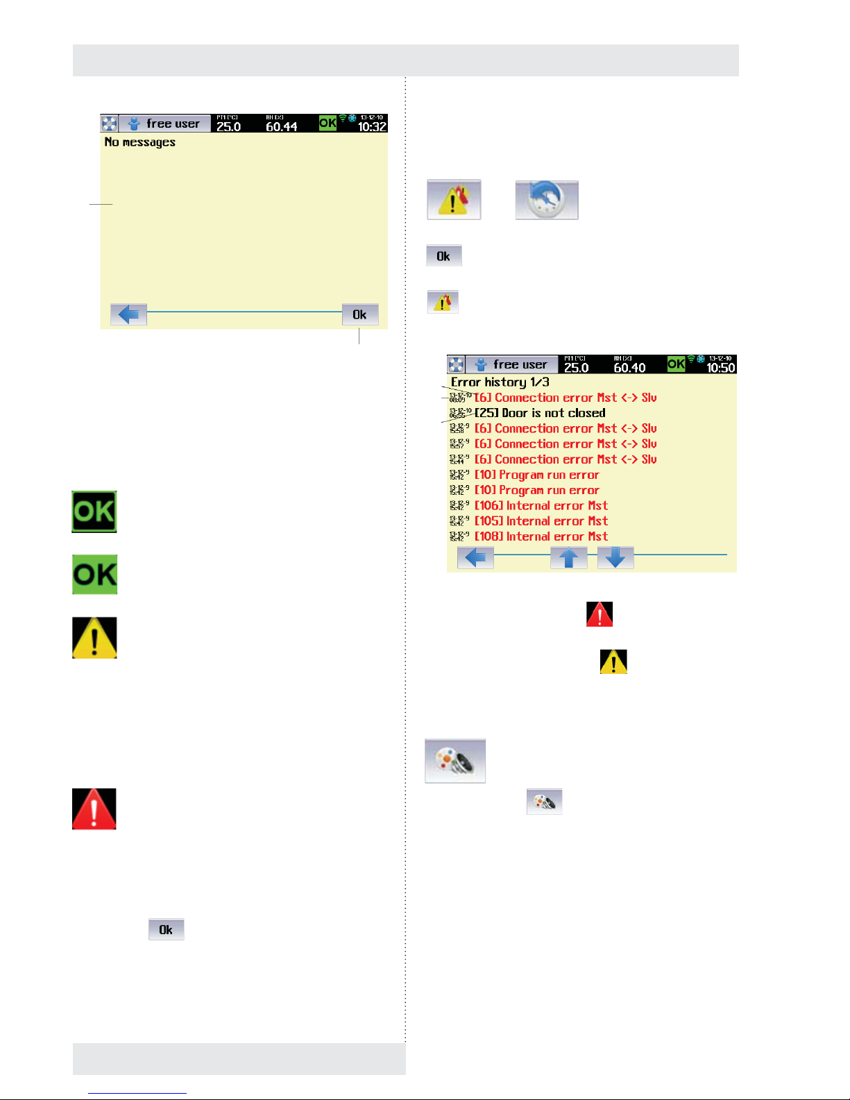
Fig. 21
(1) Current error messages.
(2) Button for confi rming all displayed errors.
The list of current error messages can also be displayed
by clicking the icon (10), Fig. 12; the icon can have the
following meanings:
No error messages - program is not running.
● ED signal light is green (3), (Fig. 4).
No error messages - program is running.
● LED signal light is green.
Warning.
● The fl ashing symbol is displayed if a
non-critical fault occurs, i.e. a fault which does
not prevent the program from running. After
pressing OK to confi rm, the symbol will stop
fl ashing, although it remains on the toolbar if
the fault is still present.
● The LED signal light acts the same as the
symbol – it fl ashes (lights up) orange.
Error.
● The fl ashing symbol warns the user that a
serious fault has occurred while the program
is running. Upon this kind of error the program
is stopped and the system awaits
confi rmation from the user. After pressing
. the symbol will stop fl ashing,
although it remains on the toolbar if the
fault is still present. The program may only be
restarted once the cause of the error has
been rectifi ed. These errors are displayed in
red in the list.
(1)
(4)
● The LED signal light fl ashes (lights up) red.
8.3.3.2 HISTORY OF FAULTS
→
After fault elimination and after confi rmation by push button
the fault is transferred to the history of faults
(Fig. 22). You can display the history of faults by pressing
in the menu for device setting (Fig. 13). The list
displays last thirty fault events.
Fig. 22
(1) Fault occurrence record ( ).
(2) Date and time of occurrence
(3) Warning occurrence record (
).
8.3.4 DISPLAY AND SOUNDS
By clicking on icon (Fig. 13), you will display the
menu for setting the display appearance and selections for
sound signals.
(1)
(2)
(3)
Instructions for use
18 CLIMACELL EVO_np_en_1401_mmm_V1.01

Fig. 23
(1) Colour profi le setting.
(2) Volume level setting.
(3) Acoustic indication options.
8.3.5 DEVICE MAINTENANCE MENU
Fig. 24
8.3.5.1 SINGLE DEFROSTING
→ Defrosting
It is suitable to use single defrosting mainly in programs
with long-term intensive cooling, when the condensate
gets frostbitten in the chamber and on the cooling system
of the device. In the course of single defrosting, the forst is
effi ciently removed. The operation cannot be activated when
(1) (2)
(3)
the program is running. Defrosting is ctivated in the device
maintenance menu.
Warning:
In case of single defrosting the temperature in the
chamber of the device increases to 50 °C, so take the
tested samples out of the incubator so as to avoid their
damage.
Note:
It is necessary to distinguish between automatic defrosting
of cooling system (see 8.4.3) and single defrosting of the
whole device. Automatic defrosting removes icing from the
cooling system of the device only (and so it increases its
effi ciency) and it is performed automatically in the course of
the program operation. Single defrosting removes icing from
the whole device and it cannot be run while the rpogramn is
running.
Fig. 25
(1) Defrosting program parameters.
(2) Warning regarding objects that must be taken out of
the device.
- This option must be ticked, otherwise it is not
possible to start the program.
(3) Defrosting program start.
8.3.5.2 DECONTAMINATION
→ Decontamination
In the course of decontamination, the operation space of the
chamber faces high temperature. The initial parameters for
exposition are 160 °C and 30 minutes. These values may
be adjusted according to client´s requirements (a service
intervention is necessary).
(1)
(2)
(3)
Instructions for use
CLIMACELL EVO_np_en_1401_mmm_V1.01 19

Instructions for use
20 CLIMACELL EVO_np_en_1401_mmm_V1.01
Notes:
- Decontamination is not possible in some versions of the
device as the high temperature could damage some
parts of the device and that is why it is factory blocked.
- Decontamination is blocked for the version with
exposition lighting.
Warning:
Before start of the decontamination program it is
absolutely necessary to take out of the device all and
any objects and accessories that could be damaged or
destroyed by high temperature infl uence!
These include mainly:
● tested samples
● racks with exposition lighting
● lighting intensity sensors
● CO
2
sensor.
After selection of decontamination (Fig. 24) there will be
displayed a menu for the decontamination program start:
Fig. 26
(1) Decontamination program parameters.
(2) Warning regarding objects that must be taken out of
the device.
(3) Decontamination program start.
Note:
Options (1), (2) must be ticked, otherwse it is not possible to
start the program..
8.3.5.3 DRYING
→ Drying
Drying removes in an optimal way all and any residuals of
condensed humidity from the chamber of the device.
● In the course of drying, the fan revolutions are set to
100 % and temperature in the chamber is kept around
40 °C. Before start of drying it is necessary to take out of
the device all and any material that could be damaged
by the above stated temperature.
Fig. 27
(1) Drying parameters.
(2) Warning of the material that must be taken out of the
device.
(3) Start of drying.
Note:
So as to reach intensive chamber ventilation it is required
for the door of the device to be open before start of drying.
Fig. 28
8.3.6 CURRENT DATE AND TIME
SETTING
(1)
(2)
(3)
(1)
(2)
(3)

CLIMACELL EVO_np_en_1401_mmm_V1.01 21
Instructions for use
Fig. 29
(1) Current date.
(2) Winter time.
(3) Time delay in hours in case of transfer to summer time.
- Here you can easily move time to summer (winter)
time. Change in this position means a change
of time in upper bar. It is not possible to perform
such movement when the program is running or in
delayed program start mode.
(4) Current time.
8.3.7 COMMUNICATION – ACTIVATION
In the Communication menu there is set the communication
interface for the application WarmComm4, there is also
performed activation of Wifi connection and e-mail account.
Note:
Selections LAN, E-mail sending of reports and Wifi are
available only at devices with communication module, see
6.15.
Fig. 30
(1) Communication interface for WarmComm4
(2) Identifi cation number of the device
- The number allows distinguishing of individual
devices in cases when a user uses several
CLIMACELL EVO devices at once.
- Displaying the device identifi cation number on the
device display - see 8.4.7.
(3) E-mail account activation, see 8.3.7.2.
(4) Wifi options
- When this option is selected, there are found
access points of available WLAN.
- A red cross means that Wifi connection is not
active.
8.3.7.1 WIFI CONNECTION ACTIVATION
By clicking the push button (3), see Fig. 30, you will display
a list of available access points.
Fig. 31
(1) Example of the list of access points found.
- In our case there was selected TechLink01
WEP64.
After selecting the access point there is required a password
for access to WLAN.
Fig. 32
(1)
(2)
(3)
(4)
(1)
(2)
(3)
(4)
(1)
(1)
(2)

Instructions for use
22 CLIMACELL EVO_np_en_1401_mmm_V1.01
(1) Password Index.
- The user may have as many as four passwords
for access to the access point. The password
index defi nes which of the passwords is used.
(2) Password.
- It is provided by WLAN administrator.
After password entering there is displayed the access point
which the connection has been established with.
Fig. 33
(1) Access point which the connection has been
established with.
8.3.7.2 E-MAIL ACCOUNT ACTIVATION
By pushing the push button (2), Fig. 30, there will be
displayed a screen for e-mail account login.
Fig. 34
(1) Name for e-mail account login.
(2) Password for e-mail account login.
Note:
- The proper e-mail account activation must be preceded
by its creation. It is possible to create the account on any
server providing e-mail services. Contact your system
administrator to create an account, respectively use
services of any of public e-mail service providers (www.
gmail.com, www.yahoo.com, etc).
- When creating an e-mail account, the user obtains a
unique name and password for his/her account. Enter
the data to positions (1) and (2), Fig. 34.
- For e-mai communication setting, see also 8.3.10.1.3.
After successful login there is a green tick in the e-mail
account push button and the name of then account is
displayed (Fig. 35).
Fig. 35
(1) E-mail account.
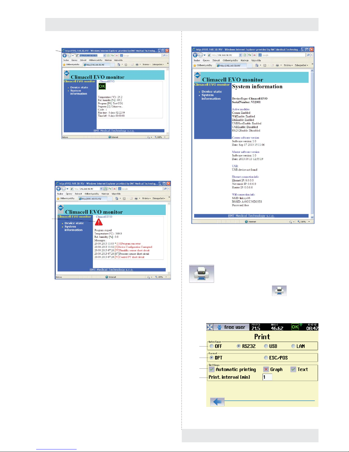
8.3.7.3 WIFI CONNECTION VIA INTERNET
BROWSER
CLIMACELL EVO provides the possibility of remote
monitoring of the device status. The wifi web server runs on
communication module and it is possible to connect to it via
ordinary Internet browser.
To establish connection with CLIMACELL EVO proceed as
follows:
1. Connect the device to local network and confi gure it
correctly - see 8.3.7.1 a 8.3.10.1.2.
2. From the system information panel 2/2 (Fig. 74) read the
pre-set IP address for WIFI.
3. Insert the address to the address line of the web browser
in PC, connected to the same local network as the
device.
4. The status of the device will be read on the web site, see
Fig. 36.
5. The last error message will be displayed after clicking on
the icon
, see Fig. 37.
6. System information will be displayed by clicking on
“System Information”.
See Fig. 38.
(1)
(1)
(2)
(1)
Instructions for use
CLIMACELL EVO_np_en_1401_mmm_V1.01 23
Fig. 36
(1) IP address of Wifi .
Fig. 37
(1) Icon for faults displaying.
Fig. 38
8.3.8 PRINT
The menu is displayed using the icon (Fig. 13).
Note:
We recommend use of the printer DPT6333, see 6.16.
Fig. 39
(1)
(1)
(1)
(2)
(3)
(4)

Instructions for use
24 CLIMACELL EVO_np_en_1401_mmm_V1.01
(1) Communication interface selection.
(2) Data format supported by the printer
- The data format is set in the technical specifi cation
of the printer. For the printer DPT6333 select
„DPT“.
(3) Options for printing.
- Automatic printing – a protocol is automatically
printed after the prograam termination.
- Graph – only the graph is printed.
- Text – only the text is printed.
(4) Print interval.
- It sets the printing period – it is possible to set 1
up to 999 minutes.
8.3.8.1 PROTOCOL PRINTING
Connect the printer and the device using the cable
according to 4.3. The connector for RS232 can be found on
the communication panel in the rear part of the device
(Fig. 3).
Connect the printer to power supply and switch on the
power switch (proceed according to instructions for use of
the printer). The printer may receive data from the device
while being in ON-LINE mode (push button SEL).
Select the interface (RS232).
Set the printing mode.
The printout contains:
- Printout heading:
o device type,
o serial number,
o batch number,
o program parameters,
o printing interval.
- Program data:
o program start time,
o values of items in given time.
Notes:
- A new heading is printed in case of program parameters
change.
- In case of device feeding cut off there is printed a
message after power supply restoration
→ Network
cut off.
- Setting of DIP switches on the printer DPT-6333:
1 - OFF
2 - OFF
3 - ON
4 - OFF
5 - OFF
6 - OFF.
8.3.9 BACKUP
CLIMACELL EVO allows performance of backup of some
important settings of the device (list of programs, list of
users, device confi guration). It is possible to use saved
data for consequent restoration of original setting or for
confi guration of another device. The menu is activated by
the icon
(Fig. 13). As a recording medium it is
possible to use SDHC card or USB fl ash disc. The card is
inserted to the appropriate slot on the control panel, the
USB fl ash disc is connected via the USB Host connector in
the rear part of the device.
Note:
For the USB fl ash disc connection the device must be
equipped with the communication module (optional
equipment of the device).
Fig. 40
8.3.10 SERVICE SETTING
8.3.10.1 COMMUNICATION – SETTINGS
→ Communication
Notes:
- Setting the communication interface of the device
supposes basic knowledge in the fi eld of computer
networks. In case of any unclear matters please contact
your information system administrator.

Instructions for use
CLIMACELL EVO_np_en_1401_mmm_V1.01 25
- The settings described in this chapter suppose that the
device is equipped with communication module, see
6.15.
8.3.10.1.1 ETHERNET SETTING
The communication interface of the device allows its
inclusion to LAN. An example of setting is shown in Fig. 41.
Fig. 41
(1) Ethernet activation.
(2) DHCP
- The user has two possibilities to get the IP
address of the device within LAN:
o IP address is assigned by the network
administrator (see below).
o the DHCP option is ticked – then, the
IP address is assigned to the device
automatically through the DHCP server.
(3) IP address of the device.
- Assigned by the LAN administrator.
(4) Sub-net mask.
- The sub-net mask is provided by the LAN
administrator.
(5) Initial gate.
- IP address of the router.
- Get information from the LAN administrator.
(6) DNS
- Address of Local DNS (Domain Name System).
- Get information from the LAN administrator.
(7) MAC
- A unique address of each network device.
- It is factory adjusted but it can be changed if
necessary.
- If there is set the MAC address 00-00-00-00-0000, the device uses the MAC address pre-set
from the factory. The address is stated in system
information, see 8.6.
- If the user wants to use aome other address but
the initial one, he may re-type it in this fi eld.
- After editing, you must switch the device on and
off using the push button ON/OFF!
(8) Ethernet setting.
(9) Wifi setting.
(10) E-mail setting.
(11) Web site setting.
8.3.10.1.2 WIFI SETTING
Fig. 42
(1) Wifi activation
(2) Automatic assignment of the IP address by the DHCP
server.
- See 8.3.10.1.1.
(3) IP address of the device.
- IP address of the device within WLAN.
- Assigned by the WLAN administrator
(4) Sub-net mask.
- Get information from the WLAN administrator.
(5) Initial gate.
(6) DNS.
- Address of Local DNS (Domain Name System).
- Get information from the WLAN administrator.
(7) Web server activation.
- On the communication module it is possible to
activate web server, allowing the user to monitor
the status of the device, see 8.3.7.3.
(8) Roaming.
- The device automatically connects to the access
point with the strongest signal.
(1)
(3)
(4)
(5)
(6)
(7)
(2)
(8) (9) (10)
(2)
(1)
(3)
(4)
(5)
(7)
(8)

Instructions for use
26 CLIMACELL EVO_np_en_1401_mmm_V1.01
8.3.10.1.3 E-MAIL SETTING
Fig. 43
(1) Sending
- Switched off / via Wifi / via Ethernet.
(2) SMTP.
- The address of the SMTP server – the address
of the server where the user´s e-mail account
is created. In case of a request for e-mail
communication CLIMACELL EVO connects with
the server and the user logins to his account (see
8.3.7.2), then it is possible to send e-mails to any
address.
- For address of the e-mail server contact your
information system administrator respectively you
can use any of public providers of e-mail services,
e.g. www.gmail.com etc.
(3) E-mail address.
- Target address, to which the e-mails are to be
sent.
- There may be any address for which the
e-mail server defi ned by address (2) sends the
messages from CLIMACELL EVO.
8.3.10.2 TOUCH PANEL CORRECTION
→ Touch Surface Offset
In this menu it is possible to calibrate the touch panel in
such a way so as the push buttons displayed on the display
exactly match the active area on the touch panel. With any
touch of the relevant push button, the active touch area on
the touch panel moves in one pixel in specifi ed direction.
Maximal adjustable variation is 100 pixels in any direction.
The initial value is x = 0, y = 0.
Note:
Display resolution is 640 x 480 pixels.
(1)
(2)
(3)
Fig. 44
(1) Current value of calibration in pixels for axis x
and y
(2) Push buttons for movement of active fi eld of touch
panel in given direction.
(3) New touch surface after movement downwards
(Δx = 0, Δy = -20).
- The fi eld where push buttons react to touch was
moved in 20 pixels downwards.
8.3.10.3 UNITS
→ Units
Selection of units for temperature and pressure.
Fig. 45
(1)
(2)
(3)
Instructions for use
CLIMACELL EVO_np_en_1401_mmm_V1.01 27
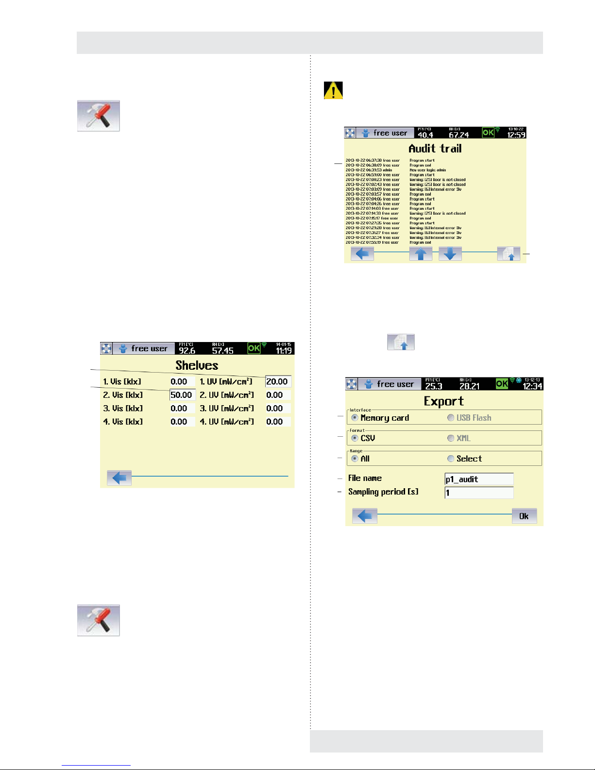
8.3.10.4 RACK
→ Rack
This service menu serves for entering the value of VIS and
UV light intensity under individual light racks in case that
the device is not equipped with sensors for light intensity
measuring (optional equipment, see 6.11).
The procedure is as follows:
1. The relevant rack is lit to maximal intensity (100 %).
2. The user uses an external measuring gauge for
measuring the intensity of visible light IVIS [k.lx],
respectively intensity of UV radiation IUV [mW/cm2]
below the relevant rack, on the exposed material
position.
3. The measured value is entered to the menu according to
Fig. 46 and it is saved in the device memory.
4. The saved value of light intensity will be used for
calculation of exposition time in programs with light
exposition (8.4.4.1).
Fig. 46
(1) Intensity of UV radiation measured below the fi rst UV
rack.
(2) Intensity of visible light measured below the second
rack.
8.3.10.5 AUDIT TRAIL
→ Audit trail
The audit trail contains a chronological record of all action
performed using the device. The minimum length of each
recorded section is ten years, although this may be longer
depending on the frequency of the work. Once the memory
capacity allocated for the audit trail reaches 90 %, a warning
. is issued. A service call-out is required to restore full
capacity.
Fig. 47
(1) Audit trail records.
(2) Button for export.
The push button
displays a menu for the audit trail
export.
Fig. 48
(1) Memory medium selection.
- USB fl ash disk is allowed only with devices with
communication module, see 6.15.
(2) Record format.
- Format CSV is suitable for export to the
application Microsoft Excel.
- XML is a universal format supported by many
applications.
(3) Export range.
- Everything – there is performed the export of
complete audit trail.
- Selection - export starts from the fi rst record on
current page. Number of exported records is set
by the item (5).
(1)
(2)
(1)
(2)
(1)
(2)
(3)
(4)
(5)

Instructions for use
28 CLIMACELL EVO_np_en_1401_mmm_V1.01
(4) File name.
- 8 characters as a maximum.
(5) Number of exported records.
8.3.10.6 OVERVIEW OF INPUTS AND OUTPUTS
This menu provides information on statuses of all the
sensors and action elements within the whole device. It
serves mainly for service purposes and it may be used in
remote diagnostics of the device. There are displayed the
data from all the sensors and current statuses of all the
action elements in the device.
8.3.10.6.1 ANALOGUE ITEMS
Fig. 49
(1) Analogue Inputs
- A set of analogue items measured within the
whole device (temperature, pressure, humidity,
concentration CO
2
, backup battery voltage, data
from light sensors).
(2) Analogue Outputs.
- Analogue outputs mean the level of analogue
control signals, i.e. mainly signals for lighting
intensity control.
(3) Digital inputs and outputs displaying.
8.3.10.6.2 DIGITAL INPUTS AND OUTPUTS
Fig. 50
(1) Digital Outputs.
- Output signals for control of individual action
elements of the device.
(2) Digital Inputs
- In1 up to In8 are digital inputs. The information
on statuses of terminal switches and comparators
within the scope of the device.
(3) Transfer to analogue items displaying.
8.3.11 TESTS
The tests serve for checking the correct function of the
device.
8.3.11.1 COOLING TEST
We recommend for the cooling test to be performed in case
of any suspicion of impaired effi ciency of the cooling system.
The proper test is performed on an empty device and it
consists of three phases:
Test phase Description
1 Start up to temperature 22 °C.
2 Lead time at temperature of 22 °C for the period of
10 minutes
3 Cooling from 22 °C to 10 °C. The cooling is
switched on to maximal output
(1)
(2)
(3)
(1) (2)
(3)

Instructions for use
CLIMACELL EVO_np_en_1401_mmm_V1.01 29
Fig. 51
(1) Test name
(2) Total test time.
(3) Current temperature.
(4) Current test phase.
(5) Current test phase time.
- In the end of the test, this position will continue to
display time of phase „3“ (cooling 22 °C →
10 °C). Compare the time with values in the table,
see chapter 11.1 „Cooling time“.
Tolerance +/- 20 %.
(6) Start.
8.4 PROGRAMS
The device’s memory can store up to 100 programs. Each
program may be broken down into 100 fully confi gurable
sub segments
Shows Fig. 55 an example of program P1, consisting of six
segments S1 up to S6. Each segment is clearly defi ned in
terms of length and the temperature to be attained in that
particular segment. For example, the fi rst segment S1 has
the time t1 and the end temperature T1 (i.e. must run to
temperature T1 at time t1). The end temperature of segment
S2 is the same as that for S1, and is therefore horizontal.
The required end temperature for segment S5 is lower than
for segment S4 – it is decreasing.
8.4.1 LIST OF PROGRAMS
Start setting the program by pressing (Fig. 12).
This displays the home screen with the list of programs. The
user may select from program P1 to P100 (Fig. 52).
Fig. 52
(1) Push buttons for relevant program selection.
8.4.2 DEFINITION OF PROGRAM
Fig. 53
(1) Program name.
(2) Description of program
(3) Safety thermostat settings – lower limit.
- See 8.4.2.1
(4) Safety thermostat settings – upper limit.
(5) Warning / error selection
- Selects how the device acts if the temperature
rises above (falls below) the set limit. See 8.4.2.1.
(6) Condition for ending the segment:
- Temperature + time – the segment ends only
if the set time has elapsed and the required
temperature has also been attained. If at least one
of these conditions is not met (i.e. the required
temperature has not been attained or the set time
has not yet elapsed), the segment continues.
- Time – the segment ends after the set time has
elapsed, regardless of whether or not the required
temperature has been attained.
(1)
(2)
(3)
(4)
(5)
(6)
(1)
(2)
(6)
(7)
(9)
(1)
(3)
(4)
(5)
(8)
(10)

Instructions for use
30 CLIMACELL EVO_np_en_1401_mmm_V1.01
- Exposition – the segment is terminated in case
that there was reached the required exposition of
visible light (klx.h) or UV radiation (mW.h/cm
2
).
The exposition selection is possible only at
devices with exposition lighting and sensors for
measuring the light intensity (see 6.10 and 6.11).
For setting of programs with light exposition see
8.4.4.1.
(7) Number of cycles.
- May be set within the range 1 to 9999.
(8) Infi nite last segment.
(9) Selection of programs chaining.
- Another program may follow after the program
termination.
(10) The following program selection.
8.4.2.1 SAFETY THERMOSTAT
The safety thermostat is used to protect the exposed
material, the incubator itself and its surroundings if the
temperature in the chamber of the device exceeds (falls
below) the maximum (minimum) limit or in the case of
regulation complications. Depending on setting of the option
(3) and (4), Fig. 53 during activation of protective thermostat
there is announced warning (
) or fault ( ).
For more details, see 8.3.3.
● If, during regulation, the temperature moves beyond the
monitored zone, the heating (cooling) is disconnected.
If the temperature spontaneously moves back within the
permissible zone, regulation recommences. The device
acts as if a warning has occurred.
● If, during regulation, the temperature moves beyond the
monitored zone, the heating (cooling) is permanently
disconnected. Regulation cannot continue without the
operator’s intervention. The device acts as if an error
has occurred.
8.4.3 PROGRAM CONFIGURATION
This menu is used to select variables and accessories that
are to be active in the program in question.
Notes:
- The variables that can be selected in this menu depend
on the specifi c confi guration of the device
- The options CO
2
, Internal socket, UV lighting, VIS
lighting, Defrosting are only available on devices with the
appropriate optional equipment,see 6.9, 6.10, 6.14.
Fig. 54
(1) CO2
- Optional device accessories.
- For devices with CO
2
regulation.
(2) Internal socket.
- Optional device accessories, see 6.9.
- In the course of the program, this socket may be
switched on (switched off), see 8.4.4.
(3) Light exposition – visible light
- Optional device accessories, see 6.10.
- For devices with lighting on light racks (visible
light).
(4) Automatic defrosting of cooling system
- Optional device accessories.
- This option should be used particularly for
programs with long-term and intense cooling,
when the condensate on the cooling unit gradually
freezes, thus reducing effi ciency. If this option is
activated, the heating medium will be injected into
the cooling system at regular intervals (depending
on the program settings and the specifi c type of
device), which will remove any ice. This is done to
minimise the impact on temperature and humidity
regulation in the working part of the incubator;
for the duration of this operation the fan speed is
reduced to 10 %.
- We recommend using this within the temperature
range from 0 °C to the ambient temperature.
(5) Transfer to segments editing.
(6) Relative humidity.
(7) Coupled racks.
- Option only for devices with UV or VIS racks
(6.10.2).
- In case of active selection, all the UV racks
(respectively all the VIS racks) are controlled
simultaneously.
If the option is not ticked, every rack is controlled
independently.
(8) UV exposition.
- Optional equipment of the device, see 6.10.2.
(5)
(1)
(2)
(3)
(4)
(6)
(7)
(8)

Instructions for use
CLIMACELL EVO_np_en_1401_mmm_V1.01 31
8.4.4 SEGMENT SETTINGS
The next step is to set the program sub-segments. Fig. 55
shows the example of temperature regulation program P1,
which consists of six segments, S1 to S6. Each segment
has a defi ned time and temperature that is to be attained
within that specifi c time.
Fig. 55
The parameters of each segment can be set in the segment
editing menu, which is reached by pressing
(Fig. 56).
Fig. 56
(1) Segment name.
(2) Required temperature at end of segment.
- Temperature to be attained at the end of the
segment.
(3) Required VIS lighting intensity at end of segment.
- Only on devices with light racks, see 6.10.
(4) Required fan speed at end of segment.
-
Decrease of revolutions may have negative
effect on precision of temperature regulation
and relative humidity regulation as well as to
space thermo homogeneity in the chamber of the
incubator.
- For optimal regulation we recommend setting to
100 %.
(5) Switching on the internal socket.
- See 6.9.
- The socket may be switched on (off) within the
segment.
(6) Length of segment
(7) Required humidity at end of segment.
(8) UV lighting intensity at the end of the segment.
- Only on devices with light racks, see 6.10.
(9) The required CO
2
concentration at the end of the
segment..
- Only on devices with CO
2
regulation, see 6.14.
(10) Alarm settings.
- See 8.4.4.2.
(11) Switch to next segment.
(12) Delete segment.
(13) Add segment.
Notes:
- The target value of the horizontal segment is the
same as the target value of the previous segment. For
example, the required temperature for segment S2
(Fig. 55) is the same as for the previous segment (S1),
and it is therefore horizontal.
- If a blank character is inserted into the variable target
value column (i.e. the column is cleared by pressing
), that variable will not be regulated in that
segment. If, for example, no value is entered for any of
the variables in the 1st segment, the device will not be
regulated at all for the defi ned period of time. This can
be used to move the start of the program by any time
period.
Allowed combinations of temperature, relative
humidity and lighting are specifi ed in chapter 8.4.5.
8.4.4.1 SETTING OF PROGRAMS WITH LIGHT
EXPOSITION
Programs with light exposition have only one segment,
in which the material under an appropriate rack faces
the infl uence of UV (VIS) light. The intensity of lighting of
all the racks is set during material exposition to maximal
value (100 %). The user sets the required exposition in the
menu for segment setting (Fig. 57). The exposition starts
automatically after reaching the required parameters in
the device chamber (temperature, humidity and possibly
others). The light intensity below the relevant rack is
measured by a sensor. After exposition time expiration the
lighting is switched off.
(6)
(7)
(8)
(9)
(1)
(2)
(3)
(4)
(5)
(10) (11) (12) (13)

Instructions for use
32 CLIMACELL EVO_np_en_1401_mmm_V1.01
Note:
- A condition for fi nishing a program in programs with light
exposition is the selected exposition (see Fig. 53).
- In case of the device not to be equipped with sensors for
light intensity measuring, there must be set the value of
VIS or UV light intensity according to 8.3.10.4.
Fig. 57
(1) Required exposition conditions.
(2) Light exposition for individual racks.
8.4.4.2 ALARMY
Alarms warn the user that one of the regulated variables has
moved outside the pre-set limits. The temperature, relative
humidity and CO
2
concentration can be monitored (CO2 is
an optional device accessory, see 6.14). How the device
acts when the alarm is triggered depends on the settings for
the button (3), fi g 58, and is the same as when a warning or
error occurs (see 8.3.3).
Fig. 58
(1)
(2)
(1) Monitored variable
- Alarms may be set for temperature, humidity and
CO
2
concentration
(2) Setting monitored limits
- See fi g. 55.
- With horizontal segments the system monitors
limits defi ned by positive and negative deviations
from the required variables – segments s2, s4, s6.
- Defi nition of monitored zone for ramps – segments
s3, s5.
- If 0 % is set for a positive and negative deviation,
the alarm is switched off - segment s1. The
temperature in the chamber is them monitored by
the safety thermostat only (8.4.2.1).
(3) Device action when an alarm occurs.
-
device acts as if a critical error has occurred.
-
device acts as if a warning has occurred.
Note:
If a certain variable needs to be quickly ramped up to
its target value in a segment (typically temperature or
humidity), when switching to the next (horizontal) segment,
there may be a slight overshoot above the required value.
This cannot be completely eliminated during regulation.
Therefore, in such cases we recommend setting the alarm
limits so that the tolerated band is not too narrow, or fi rst
testing out the alarm settings.
8.4.5 TEMPERATURE AND RELATIVE
HUMIDITY SETTING AND THEIR
LIMITATIONS
The mutual relation of operation temperature (T °C) and
operation relative humidity (RH %) when setting the
operation parameters of the case depending on additional
equipment is illustrated in the enclosed scheme.
Temperature and relative Humidity Setting
and Their Limitations
Fig. 59
(3)
(2)
(1)
CLIMACELL
Lighting – door
CO
2
Lighting – racks LED
Lighting – racks –
fl uorescent lamps

Instructions for use
CLIMACELL EVO_np_en_1401_mmm_V1.01 33
8.4.6 PROGRAM START MENU
After all the segments setting and program saving we
reach the menu where it is possible to start the program
respectively to further adjust it.
Fig. 60
(1) Basic data of the program.
(2) Schematic display of the program course.
(3) Program deletion.
(4) Program adjustment.
(5) Delayed program start.
(6) Program start.
8.4.7 PROGRAMU START
The program is started by push button
, Fig. 60.
The display starts to show graphic displaying of the program
items depending on time (Fig. 61). The upper bar shows
current values of temperature and relative humidity in the
chamber.
(1)
(2)
(3) (4) (5) (6)
Fig. 61
(1) Vertical axis description – the axis for currently
displayed item (temperature).
(2) Description of vertical axis for the fi rst item
(temperature).
(3) Description of vertical axis for other items (humidity,
CO
2
, etc.)
- By touching the axis description there will be
switched over the vertical axis for the relevant
item.
(4) Protective thermostat setting – upper limit.
(5) Graphic record of second item regulation (humidity).
(6) Graphic record of fi rst item regulation (temperature).
(7) Protective thermostat setting – lower limit.
(8) Time axis description – format and scale.
- The scale is in the format of time / one graph
section.
- In our example 1 min. / section.
(9) Start of displayed time section.
- In our case there is displayed the course of
regulation in the range from 0:00 hour to 0:10 hour
as from the program start.
(10) Information on active program and segment. Field for
operation reports
(11) Stop the program.
(12) Push button for movement to the beginning of record.
(13) Program editing.
(14) Movement backward / forward
- Based on touch, the displayed fi eld of the graph
moves in the direction of negative (positive) time
axis.
(15) Change of time axis scale.
- „-“ displays a longer time interval.
- „+“ displays a shorter time interval.
(16) Push button for movement to the end of record.
(17) Graph setting (see 8.4.7.1).
(18) Displaying the time data of the program (see 8.4.7.1).
- The format of displaying depends on setting them
graph parameters - see 8.4.7.1.
- c – it has the meaning of the number of fi nished
cycles.
(1)
(2)
(3)
(4)
(5)
(6)
(7)
(8)
(9)
(10)
(11) (12) (13) (14) (15) (16) (17)
(23)
(22)
(21)
(20)
(19)
(18)

Instructions for use
34 CLIMACELL EVO_np_en_1401_mmm_V1.01
- d – it has the meaning of the number of passed
days
(19) End of displayed time interval.
(20) Movement upwards / downwards.
- Based on touch, the displayed fi eld of the graph
moves in the direction of negative (positive) axis y.
(21) Push buttons for setting the vertical axis scale.
(22) Identifi cation number of the device.
- See 8.3.7.
(23) Information on device operation.
8.4.7.1 RUNNING PROGRAM GRAPH
The parameters of the running program graph can be set
after clicking on the icon
Fig. 61.
Fig. 62
- heating
- cooling
- visible light
- UV
- visible light + UV
- USB device connected
- Wifi – full signal
- Wifi – weak signal
- Wifi – very weak signal
- Wifi – no signal
(1) Options for time displaying
- „BY END“ – it displays the time remaining by the
end of selected part of the program.
- „display days“ – it shows passed days.
- „display cycles“ – it shows passed cycles.
- Time is displayed in format HHHHH:MM:SS.
Maximal time that can be displayed is 65535
hours.
- In case of selection „Display days“ the time is
displayed in the format DDDDD:HH:MM:SS.
Maximal time that can be displayed is 65535 days.
(2) Part of the program, to which the time information
relates.
- A batch means chaining of several programs one
after the other.
(3) Displayed items selection.
- The offer in this fi eld depends on concrete
confi guration of the device.
8.4.7.2 RUNNING THE PROGRAM WITH LIGHT
EXPOSITION
In case of programs with light exposition the information
about the program is displayed in a different format
compared to other programs (exposition programs - see
8.4.4.1.).
Fig. 63
(1) Current light dose in given time.
(2) Push button for manual switch on (off) of light racks.
8.4.7.3 POSTPONED START OF PROGRAM
Postponed start of the program allows automatic start of the
program in set time. It is possible to start the program in any
point of the cycle (program, segment).
(1)
(2)
(3)
(1)
(2)

CLIMACELL EVO_np_en_1401_mmm_V1.01 35
Instructions for use
Fig. 64
(1) Automatic start date
(2) Automatic start time
(3) Segment, from which the program is to start.
(4) Cycle, from which the program is to start.
(5) Time of start within the selected segment.
(6) Start confi rmation.
Notes:
- After confi rmation of postponed start the display shows a
message with date annd time of program start. The only
active push button is that for operation cancelling.
- After confi rmation of postponed start of the program, the
user is logout in the mode of advanced administration of
users (8.3.2.2). Then, the device is in mode „no login“.
Fig. 65
(1) Date and time of postponed start.
8.4.7.4 DOOR OPENING
In case of the door to be open in the course of the program,
the fi eld (1), Fig. 67 displays a relevant message and there
is announced a warning . The device continues in
program performance, the event is recorded in audit trail.
Fig. 66
Fig. 67
(1) Message in the bar.
(2) Warning.
8.4.7.5 DOOR BLOCKING
The device may be equipped with an electromagnetic
mechanism, preventing undesirable door opening (optional
equipment of the device, see 6.4).
8.4.7.5.1 DOOR BLOCKING IN THE MODE
WITHOUT USERS ADMINISTRATION
In the mode when there is not activated advanced
administration of users, the user may manually activate
(deactivate) the door blocking. Blocking (de-blocking) is
activated by touching the icon
( ). Device
login is not required for the door control.
(1)
(2)
(3)
(4)
(5)
(6)
(1)
(1)
(2)

Instructions for use
36 CLIMACELL EVO_np_en_1401_mmm_V1.01
Fig. 68
(1) Door blocking icon
- Blocking is activated (deactivated) by touch.
8.4.7.5.2 DOOR BLOCKING IN THE MODE OF
ADVANCED USERS ADMINISTRATION
If there is activated the advanced administration of users,
the blocking control is conditioned by the user´s login. The
right to block (unblock) the door have all the defi ned users
regardless their assignment into groups. After login, the user
may activate (de-activate) blocking by touching the icon
( ). After logout of a user, the door is blocked.
In case of automatic user´s logout setting (see 8.3.2.2.1,
Fig. 16) the door is automatically blocked after specifi ed
time expiration.
8.4.7.6 CURRENTLY RUNNING PROGRAM
EDITING
The user may change parameters of currently running
program. Using push buttons
(Fig. 67) and
(Fig. 69) you can reach the menu for program editing, see
8.4.2.
(1)
Fig. 69
(1) Entry to program editing.
After fi nishing the editing, the user is asked whether he
wants to interrupt the currently running program and save
changes.
Fig. 70
After confi rmation by push button
Yes
the new setting
of the program is saved in the device memory and there is
displayed the menu for postponed start of the program (see
8.4.7.3). In this menu, the user may select the cycle of the
segment, respectively time of segment, when the program is
to start. The push button
starts the program with
new settings regardless the time specifi ed in the editing fi eld
„Time“.
(1)

Instructions for use
CLIMACELL EVO_np_en_1401_mmm_V1.01 37
8.4.7.7 POWER SUPPLY OUTAGE
In case of power supply network outage in the course of the
program ruin, all the running program settings are preserved
and even the real time clock goes on in the course of the
outage.
The device behaviour during an outage depends on setting
of the condition for the segment fi nishing (see 8.4.2):
- Temperature + time or batch
o after power supply restoration the program will
continue exactly from the point of the segment where
it was interrupted.
- Time
o after power supply restoration there will continue
exactly the time that passed from the program start.
The part of the program that should have been
performed in the course of the outage is omitted.
8.5 HISTORY OF PROTOCOLS
The history of protocols keeps information on programs run
in recent 30 days. In the protocol there are saved samples
of all the program items with a period of 1 s. The history of
protocols is displayed using the icon
, Fig. 12.
Fig. 71
(1) Date and time of program running.
(2) Program name.
(3) Protocol order in the history.
(1)
(2)
(3)
A relevant graph is displayed after selection of an item from
the list:
Fig. 72
(1) Lower limit of selection
- When touching any point of the graph, a white
cursor is displayed in the touch point.
- The push button changes the cursor colour to
green. The green cursor marks the lower limit of
the selection.
(2) Upper limit of selection (export).
- The push button changes the cursor colour to
red. The red cursor marks the upper limit of the
selection.
(3) Protocol printing.
(4) Protocol export.
(5) Cursor for lower limit of the range.
(6) Cursor for current value
(7) Cursor for upper limit of the range.
Push button
(Fig. 72) displays the menu for
protocol export.
Fig. 73
(5) (6) (7)
(1) (2) (3) (4)
(1)
(2)
(3)
(4)
(5)

Instructions for use
38 CLIMACELL EVO_np_en_1401_mmm_V1.01
(1) Memory medium selection
- USB fl ash disk is possible only with devices with
communication module, see 6.15.
(2) Record format.
- Format CSV is suitable for export to Microsoft
Excel.
(3) Export range.
- It is possible to export compete record or a part of
it.
(4) File name.
- 8 characters as a maximum.
(5) Sampling period.
- Sampling period = 1 s, means that there will be
exported all the saved samples from the selected
interval (maxima data volume). Sampling period
= 2 s, means that there will be exported every
second sample (half data volume), etc.
8.6 SYSTEM INFORMATION
After clicking the icon (Fig. 12) there will be
displayed all and any system information of the device,
values of all the measured items and status of action
elements.
Fig. 74
(1) Information on running program.
(2) Information on running segment.
(3) Currently measured values and current status of action
elements.
(1)
(2)
(3)
Fig. 75
(1) Device type and serial number.
(2) Records of tests and system updates.
(3) Main version of the system.
(4) System sub-version.
(5) Free capacity of memory for history of programs and
audit rail.
(6) Backup battery status.
(7) Connected USB device.
(8) Device setting within LAN.
(9) Device setting within WLAN.
(1)
(2)
(3)
(4)
(5)
(6)
(7)
(8)
(9)

9 LIST OF ERROR MESSAGES
Number Location Name Relevance Cause Way of elimination
1 Mst System version error Hard There is a set of fi rmware in the device
which is mutually incompatible
Contact authorised service
2 Mst Faulty program defi nition. Hard Started program is damaged or the
program version is incompatible with
the fi rmware version.
Repeat the program editing and save
the program again.
Contact authorised service in case
that the problem persists
3 Mst Faulty device
confi guration.
Hard The confi guration saved in the device
is damaged or its version does not
correspond to current version of
fi rmware.
Contact authorised service
4 Mst Faulty access rights. Hard Access rights of users saved in the
device are damaged or their version
does not correspond to current version
of fi rmware.
The administrator checks the access
rights setting.
Contact authorised service in case
that the problem persists
5 Mst Fault of connection
between Mst and Com.
Soft Error in communication with
communication module.
Contact authorised service
6 Mst Fault of connection
between Mst and Slv.
Hard Error in communication with module
Slv.
Contact authorised service
7 Mst Error in protocol
recording.
Hard Data of the protocol not entered in
internal memory of the device.
Contact authorised service
8 Mst Large-capacity memory
error.
Hard An error in work with internal memory
of the device.
Contact authorised service
9 Mst Program run error. Hard An unexpected step occurred in the
program run.
Repeat program setting, save it and
start again.
Contact authorised service in case
that the problem persists
10 Mst Discharged battery. Hard Critical level of battery voltage.
Immediate replacement necessary.
Contact authorised service
11 Mst Discharged battery. Soft Low level of battery voltage.
Replacement recommended.
Contact authorised service
12 Mst Power blackout. Hard Network feeding failure exceeding 7
days or program run not restored after
blackout due to discharged backup
battery.
Arrange for any blackout not to
exceed 7 days. In case of discharged
battery call authorised service.
13 Mst Date and time. Hard Invalid date and time. If the battery is discharged, call
authorised service.
22 Slv Too high pressure in
generator.
Hard Fault of heating body or pressure
sensor.
Contact authorised service
23 Slv High temperature in
generator.
Hard Fault of heating body or temperature
sensor for body overheating.
Contact authorised service
24 Slv Overpressure valve of
generator.
Hard There was activated the pressure fuse
of steam generator or steam leakage
detector failed.
Contact authorised service
25 Slv Door not closed. Soft Open door or faulty door switch. Check whether the door is closed,
respectively contact authorised
service.
26 Slv Generator cannot be
pressurised.
Soft Fault of heating body or pressure
sensore.
Contact authorised service
27 Slv Discharge vessel cannot
be emptied.
Soft Decreased permeability of waste water
drain (e.g. broken hose), faulty pump or
fl oating switch.
Check permeability of waste water
drain respectively contact authorised
service.
28 Slv Generator cannot be
fi lled.
Soft Decreased permeability of water intake
(e.g. broken hose), faulty pump or
fl oating switch.
Check permeability of water intake
respectively Contact authorised
service.
29 Slv Unexpected reset of Slv. Soft Short failure of feeding voltage, network
voltage oscillation
Contact authorised service in case of
repeated occurrence.
50 Mst Protective thermostat
interrupted.
Hard Contact authorised service
51 Mst Protective thermostat
short-circuited.
Hard Contact authorised service
52 Slv Regulation Pt interrupted. Hard Faulty temperature sensor. Contact authorised service
53 Slv Regulation Pt short-
circuited.
Hard Faulty temperature sensor. Contact authorised service
Instructions for use
CLIMACELL EVO_np_en_1401_mmm_V1.01 39

54 Slv Humidity sensor
interrupted.
Hard Faulty sensor or source +24 V. Contact authorised service
55 Slv Humidity sensor short-
circuited.
Hard Faulty sensor or source +24 V. Contact authorised service
56 Slv Flexible Pt 1 interrupted. Soft Faulty temperature sensor. Contact authorised service
57 Slv Flexible Pt 1 short-
circuited
Soft Faulty temperature sensor. Contact authorised service
58 Slv Flexible Pt 2 interrupted.. Soft Faulty temperature sensor. Contact authorised service
59 Slv Flexible Pt 2 short-
circuited
Soft Faulty temperature sensor. Contact authorised service
60 Slv Flexible Pt 3 interrupted. Soft Faulty temperature sensor. Contact authorised service
61 Slv Flexible Pt 3 short-
circuited.
Soft Faulty temperature sensor. Contact authorised service
62 Slv Flexible Pt 4 interrupted. Soft Faulty temperature sensor. Contact authorised service
63 Slv Flexible Pt 4 short-
circuited
Soft Faulty temperature sensor. Contact authorised service
64 Slv CO
2
sensor short-
circuited.
Soft Faulty sensor or source +24 V. Contact authorised service
65 Slv CO
2
sensor interrupted. Soft Faulty sensor or source +24 V. Contact authorised service
66 Slv Pressure sensor short-
circuited.
Soft Faulty sensor or source +24 V. Contact authorised service
67 Slv Pressure sensor
interrupted.
Soft Faulty sensor or source +24 V. Contact authorised service
68 Slv Light sensor 1 short-
circuited.
Soft Faulty sensor or source +24 V. Contact authorised service
69 Slv Light sensor 1 interrupted Soft Faulty sensor or source +24 V. Contact authorised service
70 Slv Light sensor 2 short-
circuited.
Soft Faulty sensor or source +24 V. Contact authorised service
71 Slv Light sensor 2 interrupted Soft Faulty sensor or source +24 V. Contact authorised service
72 Slv Light sensor 3 short-
circuited.
Soft Faulty sensor or source +24 V. Contact authorised service
73 Slv Light sensor 3 interrupted Soft Faulty sensor or source +24 V. Contact authorised service
74 Slv Light sensor 4 short-
circuited.
Soft Faulty sensor or source +24 V. Contact authorised service
75 Slv Light sensor 4 interrupted Soft Faulty sensor or source +24 V. Contact authorised service
76 Slv UV sensor 1 short-
circuited
Soft Faulty sensor or source +24 V. Contact authorised service
77 Slv UV sensor 1 interrupted Soft Faulty sensor or source +24 V. Contact authorised service
78 Slv UV sensor 2 short-
circuited
Soft Faulty sensor or source +24 V. Contact authorised service
79 Slv UV sensor 2 interrupted Soft Faulty sensor or source +24 V. Contact authorised service
80 Slv UV sensor 3 short-
circuited
Soft Faulty sensor or source +24 V.. Contact authorised service
81 Slv UV sensor 3 interrupted Soft Faulty sensor or source +24 V. Contact authorised service
82 Slv UV sensor 4 short-
circuited
Soft Faulty sensor or source +24 V. Contact authorised service
83 Slv UV sensor 4 interrupted Soft Faulty sensor or source +24 V. Contact authorised service
100 Mst Internal error Mst 100 Hard Fault of reading EEPROM Mst Switch the device on and off using the
network switch.
Contact authorised service in case
that the problem persists.
101 Mst Internal error Mst 101 Hard Fault of writing to EEPROM Mst Switch the device on and off using the
network switch.
Contact authorised service in case
that the problem persists.
200 Slv Internal error Slv 200 Hard Fault of reading EEPROM Slv Switch the device on and off using the
network switch.
Contact authorised service in case
that the problem persists.
201 Slv Internal error Slv 201 Hard Fault of writing to EEPROM Slv Switch the device on and off using the
network switch.
Contact authorised service in case
that the problem persists.
202 Slv Internal error Slv 202 Hard Fault of fuzzy regulator of temperature
(this should never occur)
Switch the device on and off using the
network switch.
Contact authorised service in case
that the problem persists.
Instructions for use
40 CLIMACELL EVO_np_en_1401_mmm_V1.01
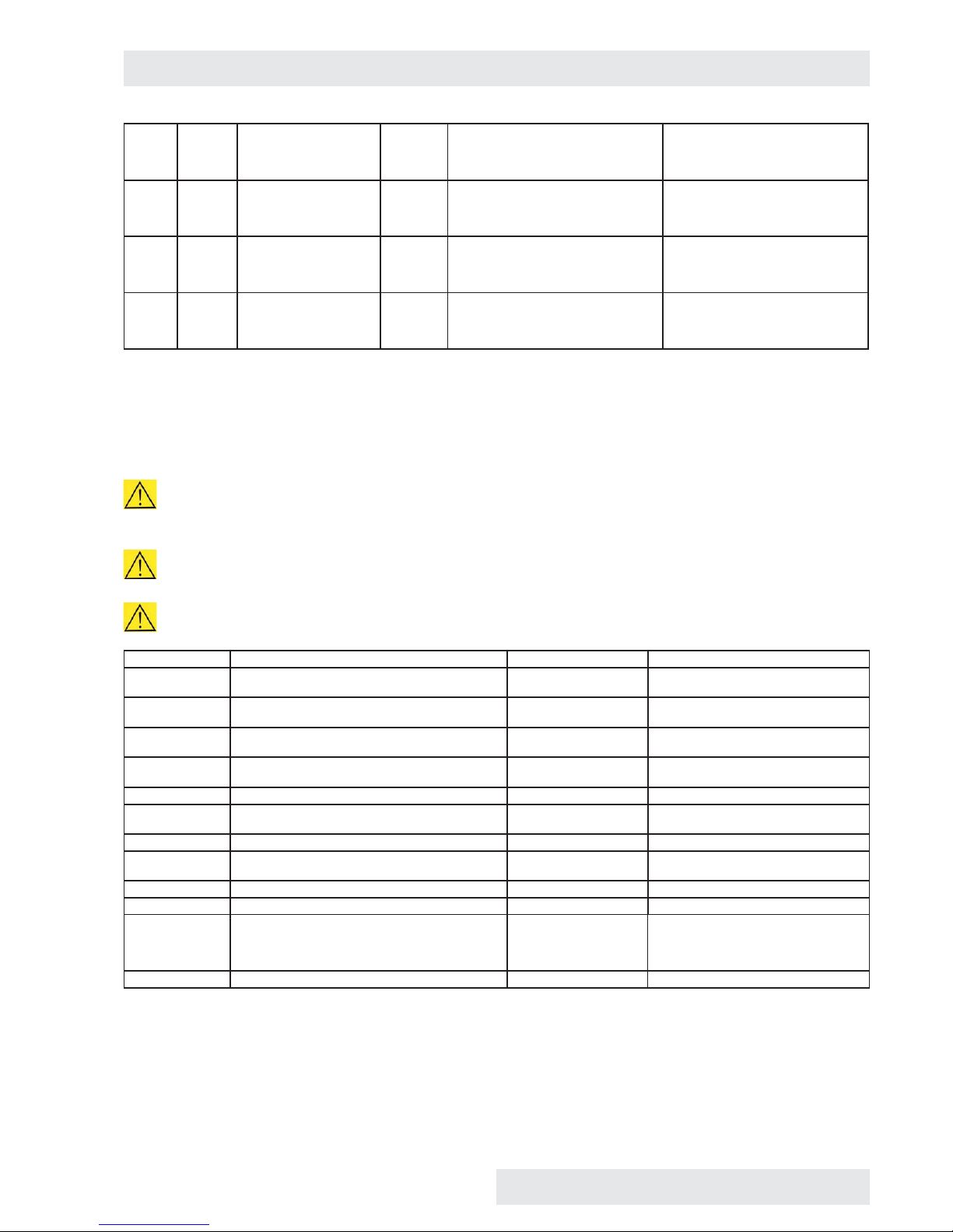
203 Slv Internal error Slv 203 Hard Fault of fuzzy regulator of RH (this
should never occur)
Switch the device on and off using the
network switch.
Contact authorised service in case
that the problem persists.
400 Comm Internal error Com 400 Soft Fault of reading EEPROM Com Switch the device on and off using the
network switch.
Contact authorised service in case
that the problem persists.
401 Comm Internal error Com 401 Soft Fault of writing to EEPROM Com Switch the device on and off using the
network switch.
Contact authorised service in case
that the problem persists.
403 Comm Internal error Com 403 Soft Unexpected reset Com Switch the device on and off using the
network switch.
Contact authorised service in case
that the problem persists.
10 DEVICE MAINTENANCE
10.1 MAINTENANCE PLAN
In case of long-term cut off of the device discharge water from the cask, generator and waste vessel. Avoid any device
pollution with ditch water. Dry the device and its parts and we also recommend its washing with suitable disinfection means.
Perform any replacement, setting, cleaning, etc. only with cooled down and disconnected device!
In case of the device to be used in any other but recommended way, the device protection may be impaired.
Frequency Controlled part Performed by Note
continuously Control of hoses and hose connections for leakage,
cleanness of mesh on submersible pump
staff
continuously Control of water quantity and cleanness in the cask
(min. level height 25 cm)
staff Pollution may occur after long-term
set-off
continuously Control of waste vessel cleanness staff Pollution may occur after long-term
set-off
continuously Cleaning of inner sheets, chamber, shell, touch
screen
staff As needed
continuously Control of door tightness staff Replacement, as needed
min. 1/2 year Visual control of integrity of insulation of fl exible
temperature sensors
staff
1 year Control of door locking mechanism service
1 year Condensate cleaning in cooling circuit service Dirt between lamellas impairs the cooling
circuit function
1 year Protective thermostat control service
1 year Relief valve functionality control service
1 year Control of electric installation – mainly integrity
of insulation of conductors, intake, connection
and protective clamps, strength of conductors
connection in clamps
service Protective connection resistance is
< 0,1 Ohm, the intake resistance is not
included
1 year Control of hose connection CO
2
service
Instructions for use
CLIMACELL EVO_np_en_1401_mmm_V1.01 41

10.2 DOOR SEALING REPLACEMENT
(1) Outer door sealing (m. No. 0672719 size 111 - 707)
(2) Glass door sealing (m. No. 0672718)
(3) Sealing between doors (m. No. 0672720, only size
707)
(4) Sealing of outer door, different for size 1212.
Fig. 76
a) The sealing (1) is inserted between the chamber and the
shell.
b) The sealings (2) and (3) are put on the sheet edge – you
can remove them easily (start from the bottom centre).
c) Re-apply a new sealing on the edge (start from the
bottom centre).
10.3 DOOR ADJUSTMENT
The glass door has a fi xed position and it can be only turned
around its axis or get out of hinges.
The outer sheet door is adjustable in all the four positions
(see Fig. 76):
a) (1a) – unscrew three cross screws and extend the super
structure towards the rear part of the device.
b) (1), (2) – four screws with inner hexagon (imbus 6).
c) (3), (4) – screws secured with a nut (cross-head
screwdriver, wrench 10).
Adjust the door in such a way so as – after their closing –
the rubber sealing of the chamber is pushed on the whole
circumference to the sheet of the fl oating door. Check it in
such a way that before full closing of the door insert a sheet
of paper between the sealing and the sheet of the fl oating
door – after the door closing, the paper may be taken out
based on slight resistance.
Fig. 77
Instructions for use
42 CLIMACELL EVO_np_en_1401_mmm_V1.01

10.4 ACCUMULATION OF CONDENSED WATER STEAM
When the incubator is operated under specifi c conditions (high humidity), condensate may accumulate in the space between
the glass door and outer door. The condensate is collected below the glass door and it is taken away to the waste vessel placed
below the device.
10.5 DEVICE CLEANING AND DECONTAMINATION
Clean only cold and mains disconnected device!
Clean inner walls (removable) with water with detergent, respectively use suitable chemical means. You can use the same
means for cleaning the interior of the chamber after removal of inner walls - see Fig. 77.
Clean the external surface of the device shell only with cloth dampened with water and detergent.
Take care for water not to fl ow behind the control panel.
Clean the touch screen with screen-cleaning means only.
Do not use any abrasive cleaning means – they may cause sheet scratching.
While handling the inner sheets in the chamber take extreme care not to cut the chamber sealing.
When disconnecting the waste vessel connector hold the female connector and pull the male connector.
Dismantling of internal walls – according to arrows
(1) – glass door, (2) – screens, (3) – upper wall, (4) – side walls, (5) – bottom, (6) – rear wall
You can assemble the chamber by reverse procedure. Take care for all the stops to fi t each other.
Fig. 78
Instructions for use
CLIMACELL EVO_np_en_1401_mmm_V1.01 43

Instructions for use
44 CLIMACELL EVO_np_en_1401_mmm_V1.01
In case of contaminated material leakage to the
chamber of the device, the user is responsible for
appropriate performance of decontamination of all and
any contaminated surfaces with suitable and approved
disinfection means.
Before using any other method of cleaning or
decontamination than the methods recommended by us it is
purposeful for the user to check at the manufacturer that the
method could not do any harm to the device.
Waste vessel dismantling – according to arrows
(1) – Male / female connector (pump and level switch
feeding), (2) – Vessel for waste water (with a pump, level
switch and hose).
Fig. 79
10.6 STEAM GENERATOR
It is located in the rear part of the device, below the cover.
Check hose tightness only, the other parts of the generator
will be checked by a service technician. It should be
performed at least once per year.
10.7 REVISION OF ELECTRO PARTS
The temperature engineering cases are designed for basic
standard environment, the manufacturer recommends the
revision period of 1 year, unless set otherwise by local
regulations.
In case of the case to be placed in different environment,
the revision must be performed in compliance with local
standards.
The service inspection is a matter of agreement by and
between the client and service organisation.

11 TECHNICAL DATA II
11.1 OPERATION DATA
Type 111 / 111-c 222 / 222-c 404 / 404-c 707 / 707-c 1212 / 1212-c
Operation temperature *) from 0 °C to °C 100 (decontamination 160 °C) xx
from -20 °C to °C 100 (decontamination 160 °C) 70
Temperature precision space at 10 °C
at 37 °C
approximately
(±)°C
< 0,5 < 0,5 < 1 < 1 <1,5
< 0,5 < 0,5 < 1 < 1 <1,5
time approximately
(±)°C
< 0,2 < 0,2 < 0,3 < 0,4 < 0,8
Time of heating to 37 °C from ambient
temperature
min <11 <11 <22 <13 <30
Time of cooling from temperature
22 °C to 10 °C
min < 21 / < 11 <17 / <14 <19 / <21 <21 / <22 <21
Time of restoration after
30 s door opening according
to DIN 12880
at 37 °C min < 5 < 2 < 10 6 10
at 50 °C min < 6 < 3 < 13 6 10
Relative humidity range % 10 - 95
Precision
T
chamber
≥ 21 °C
time
approximately
(±) % RH
< 2
Concentration of CO
2
% 0,1 - 20 xx
Required pressure of CO
2
bar/psi 0,3 - 0,7 / 5 - 10 xx
All the data apply in empty chamber (without samples on screens) for ambient temperature of 20 - 22 °C, 100 % fan revolutions,
feeding voltage 230 V ± 10 %.
*) Option of cooling up to -20 °C, performance with decontamination – temperature 160 °C. If there is used lighting or CO
2
sensor, the allowed temperature is lower.
Instructions for use
CLIMACELL EVO_np_en_1401_mmm_V1.01 45

11.2 RACKS WITH EXPOSITION LIGHTING
FLUORESCENT LAMPS
Name CLIMACELL E 111 / 111-c 222 / 222-c 404 / 404-c 707 / 707-c 1212 / 1212-c
Width x depth x height of rack mm 539x350x90 539x500x123 539x500x123 939x512x93 539x500x123
Number of fl uorescent lamps per 1 rack pc 5 8 8 12 8
Max. number of racks in a chamber pc 2 / 2 2 / 2 3 / 4 3 / 4 12 / 12
Input per 1 rack W 75 120 120 180 120
length x diameter of fl uorescent lamp mm 450 / 26
Usable VIS source (fl uorescent lamp):
range // colour temperature
400 - 700 nm // 2700 / 3000 / 4000 / 6000 °K
Usable UV source (fl uorescent lamp):
range // maximum
300 - 400 nm // maximum 350 nm
Exposition parameters VIS
Tube type / input W/pc Luxline Plus - colour temperature 4000°K // 15 W
Lighting: in the centre of the storage
rack below the source, in the distance
from light source: 10 cm
klux ±10 % 16,5 18 18 20 18
Exposition parameters UV
Tube type / input W/pc Black light blue BLB // 15 W
Lighting: in the centre of the storage
rack below the source, in the distance
from light source: 10 cm
mW/cm
2
±10 % 5
Coverage according to EN 60529 IP 65
Number of connectors per 1 rack pc 2 2 2 4 2
Operation temperature range: rack ON, humidity OFF
1 rack °C 0 - 100 / 0 - 100 / 0 - 100 / 0 - 100 /
2 racks °C 15 - 100 / 15 - 100 /
3 racks °C xx xx 8 - 100 / 8 - 100 /
4 racks °C xx xx xx xx
12 racks °C xx xx xx xx
Operation temperature range : rack ON, humidity ON
1 rack °C 10 - 90 / 10 - 90 / 10 - 90 / 10 - 90 /
2 racks °C 17 - 90 / 15 - 90 /
3 racks °C xx xx 15 - 90 / 15 - 90 /
4 racks °C xx xx xx xx
12 racks °C xx xx xx xx
Controlled relative humidity range: rack ON (applies to temperature range 15 - 50 °C)
1 rack % RH 10 - 75 / 10 - 75 / 10 - 85 / 10 - 85 /
2 racks % RH 10 - 60 / 10 - 60 /
3 racks % RH xx xx 10 - 60 / 10 - 60 /
4 racks % RH xx xx xx xx
12 racks % RH xx xx xx xx
Operation temperature and relative humidity range: rack OFF, humidity ON
Temperature °C 10 - 90
RH % RH 10 - 95
All the data apply in empty chamber (without samples on screens) for ambient temperature of 20 - 22 °C, 100 % fan revolutions,
feeding voltage 230 V ± 10 %.
Current values of photometric items in the course of the experiment must be measured by an independent measuring gauge.
Instructions for use
46 CLIMACELL EVO_np_en_1401_mmm_V1.01
12 WARRANTY AND
SERVICE
The guarantee period is marked on the certifi cate of
warranty.
The warranty refers to manufacturing defects or material
defects on condition that:
the product has been installed and used in accordance
with the Instructions for use,
the cause of the defect was not a insuffi cient
maintenance, unqualifi ed intervention in the device or
damage through external impacts.
The warranty does not relate to natural wear of material and
to consumer material, such as e.g. door sealing, materials
for recording devices, accumulators etc. If a defect occurs,
draw claims to a warranty repair directly at the nearest
BMT service center. Please mention the device name and
type, its serial number and how the defect appears (error
message, printer record).Provided the warranty conditions
are fulfi lled there follows, according to the consideration of
the service center, the cost-free repair or replacement of the
defective part.
If the prescribed maintenance is complied with, the device
life exceeds 10 years. At the same time, this is the period
for which the manufacturer bears objective responsibility
within the meaning of EU Directive no. 85/374/EEC for any
potential damage caused by the device operation. If you
decide to continue using the device after the said period
expiration, ask the manufacturer or an authorized service
for an expertise whether or not the device can still be used
regarding its wear and tear, technical condition and service
availability.
13 TRANSPORT AND
STORAGE
The authorised person will prepare the device for transport.
The device must be transported and stored in its original
package. If you send the device back to the manufacturer
(e.g. for repair or replacement within the scope of a
claim), use the original package. Otherwise you become
responsible for possible damage during transport and the
manufacturer will exact from you some compensation for
necessary related repairs. The device may be stored in
temperatures from 0 °C up to 40 °C.
14 WAY OF
LIQUIDATION
The package is made of wood, nails, cardboard, paper and
plastics, which can be recycled as like as household waste.
For European Union countries:
A product which is no more in use, is of no use for the user
and has the
, abelling, shall be shut down by the
user who shall inform the seller (in the Czech Republic:
the manufacturer). The product may not be placed in the
communal waste and is subject to a regimen according
to WEEE (Waste Electric and Electronic Equipment) EU
Directive no. 2002/96/EC as amended.
For countries out of European Union:
The label
is valid in European Union countries only.
Ask your authorities or the device seller for detailed
information about correct liquidation of electric and
electronic devices.
Instructions for use
CLIMACELL EVO_np_en_1401_mmm_V1.01 47


MMM Medcenter Einrichtungen GmbH
Semmelweisstrasse 6
D-82152 Planegg
Germany
T. +49 89 89 92 26 20
F. +49 89 89 92 26 30
e-mail: medcenter@mmmgroup.com
Manufactured in the EU
 Loading...