

Page 1
USB Interface /USB-HUB Combo Interface Instruction manual / User Guide
DIP-SWITCH POSITION
Power
Port
Connect 12V DC
USB
Port
5
USB Interface
USB Interface / USB
USB Interface USB Interface
USB Interface
P/N#2261998USBA1-XX:
USB Interface KIT (Includes Power
Supplies & USB Host Cables)
P/N# 641-2575-00:
Cash Drawer Power Supply (12V dc)
P/N# 641-25BX-00:
USB Host Cable
GETTING STARTED:
GETTING STARTED:
GETTING STARTED:GETTING STARTED:
If you have purchased a USB-HUB Combo, proceed by always connecting the standard USB interface which serves as
the cash drawer’s connectivity first. For both types of interfaces, please follow these steps:
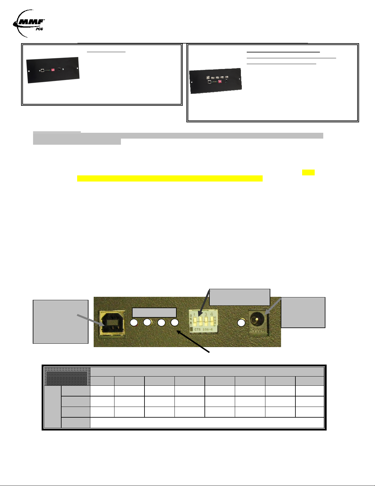
Select Cash Drawer Number with Dip Switch
The MMF POS USB Interface Board’s Dip Switch is factory defaulted to either recognize the cash
drawer as drawer number zero (0) or seven (7), see Figure 1.0 Dip-Switch Position (Default Setting).
If user decides to assign another drawer number, please follow the pin configuration illustrated in
SWITCH SETTINGS Table 1.0 or label attached to the interface for correct pin orientation. MMF
recommends selecting cash drawer number one (1) as your option.
Connect the Power Supply (12VDC / .8 Amp)
Plug the small plug tip to the interface power port in the back of the cash drawer interface as illustrated in
Figure 1. Plug the power adapter end into a 120 Volt AC Recepticle.
Always connect the power supply before the USB Cable.
Connect USB Cable
Plug the Type B connector end to the USB Port of the interface as illustrated in Figure 1 and the Type A
Connector to the USB port of the Host Computer.
Test Functionality of Interface
NOTE: Do not assign two (2) USB interface cash drawers within the same system with the same cash drawer number.
Follow the steps detailed below for ‘USB Test Utility Installation’.
Install OPOS Drivers
Follow the steps detailed below for ‘MMF OPOS Drivers Installation’.
FIGURE 1.0
/ USB----HUB Combo Interface
/ USB/ USB
HUB Combo Interface
HUB Combo InterfaceHUB Combo Interface
USB-HUB Combo Interface
(A combination of our standard USB
Interface and a 4-Port HUB)
P/N# 2261998USBA1-XX:
USB-HUB Interface KIT (Includes Power
Supplies & USB Host Cables)
P/N# 641-2575-00:
Cash Drawer Power Supply (12V dc)
P/N# 641-25CE-00:
USB Hub Power Supply (5V dc)
P/N# 641-25BX-00:
USB Host Cable
Port of Cash Drawer
Interface
Connect Type B
Connector of USB
cable Here
TABLE 1.0
SWITCH
SWITCH
SWITCH SWITCH
SETTINGS
SETTINGS
SETTINGSSETTINGS
SW1
SW1 ON OFF ON OFF ON OFF ON OFF
SW1SW1
SW2
SW2 ON ON OFF OFF ON ON OFF OFF
SW2SW2
SWITCH
SWITCH
SWITCH
SWITCH
-
-
-
-
SW3
SW3 ON ON ON ON OFF OFF OFF OFF
SW3SW3
DIP
DIP
DIP
DIP
SW4
SW4 RESERVED
SW4SW4
Note: OFF is when pins are facing down (↓). ON is when pins are facing up (↑).
Approved Date of Revision 7/10/2012 Doc. Instruction Manual
P/N: 531911900
0000 1111 2222 3333 4444 5555 6666 7777
1 2 3 4
This light should not be ON at any time
DRAWER
DRAWER NUMBER
DRAWERDRAWER
NUMBER
NUMBERNUMBER
Power Supply
Here
OFF
OFFOFF
OFF
OFFOFF
OFF
OFFOFF
Page 2
USB Interface /USB-HUB Combo Interface Instruction manual / User Guide
Solid
Intermittent
Port Powered
-
Adapter Powered
1st:Plug Power Adapter
mechanism.
NOTE 2
adapter.
TABLE 2.0
STATE
ON
See
Note 1
OFF
USB
Communication
Transmit Cash Drawer Open
Solenoid kicked
drawer open
2nd:Plug USB Cable
:
Adapter
Powered:
Draws power
from the
provided
power supply
NOTE 1
Port Powered:
Draws power
from the
computer,
which will not
provide
enough power
to operate cash
drawer’s latch
LED
NAME
LED-1 USB Cable Connected No USB Cable
LED-2
Cash Drawer Closed
Solenoid in position and
LED-3
LED-4
ready to kick drawer open
Not Recommended
1st:Plug USB Cable
2nd:Plug Power Adapter
LED-5 Power Supply Connected No Power Supply
FIGURE 1.1
USB TEST UTILITY INSTALLATION
A CD with the utility drivers and test utility (See Figure 1.1) is included
with the cash drawer. The drivers and test could also be found by logging
on to:
http://www.mmfcashdrawer.com/08/driver_downloads.html
» Click on the “Setup.exe” Icon
» Click on “Run”
» Follow through the automatic setup
» After download is completed, go to “Start” Menu
» Go to “All Programs”
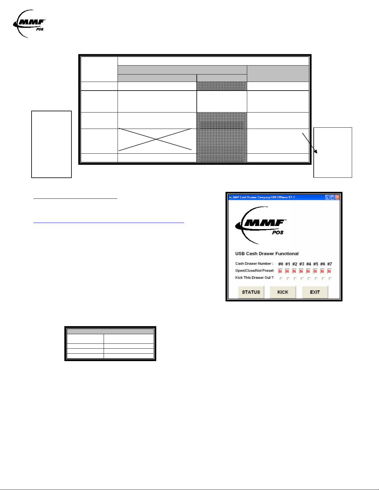
» Select the “MMF Cash Drawer Company USB CRDemo”
Download the MMF USB Driver and Test Utility file from the
website by opening the zipped file or insert CD.
» Open folder named “MMF USB_Setup”
program
Click Status, a result letter character (O/C/N) should appear in the result box under the cash drawer number
given to the unit by setting the dip switch (Step 1-Getting Started)
LEGEND
Action
Present
Closed
Opened
Result under
Assigned Drawer #
N
C
O
Make sure cash drawer is closed and the letter ‘C’ appears in the result box.
Click ‘Kick’ to open the cash drawer, the letter ‘O’ should now appear in the result box.
Repeat if necessary.
Approved Date of Revision 7/10/2012 Doc. Instruction Manual
P/N: 531911900
Page 3
USB Interface /USB-HUB Combo Interface Instruction manual / User Guide
character sensitive.
MMF OPOS DRIVER V1.13 INSTALLATION
STEP 1
Install MMF OPOS Driver V1.13, available under: http://www.mmfcashdrawer.com/08/driver_downloads.html
The user installing the MMO POS software and configuring the cash drawer devices on Windows 2000, Windows XP, and
Windows 7 is required to have Administrator Rights. Once the software is installed, all users with normal rights can use it.
STEP 2 FIGURE 1.2
If using CD, open the file named MMF OPOS 1.13
To install the driver run the file: Setup.exe.
The program will ask you to unzip, click Unzip.
» After download is completed, go to “Start” Menu
» Go to “All Programs”
» Select the “MMF Cash Drawer” program
» Select the “Configure and Test” program
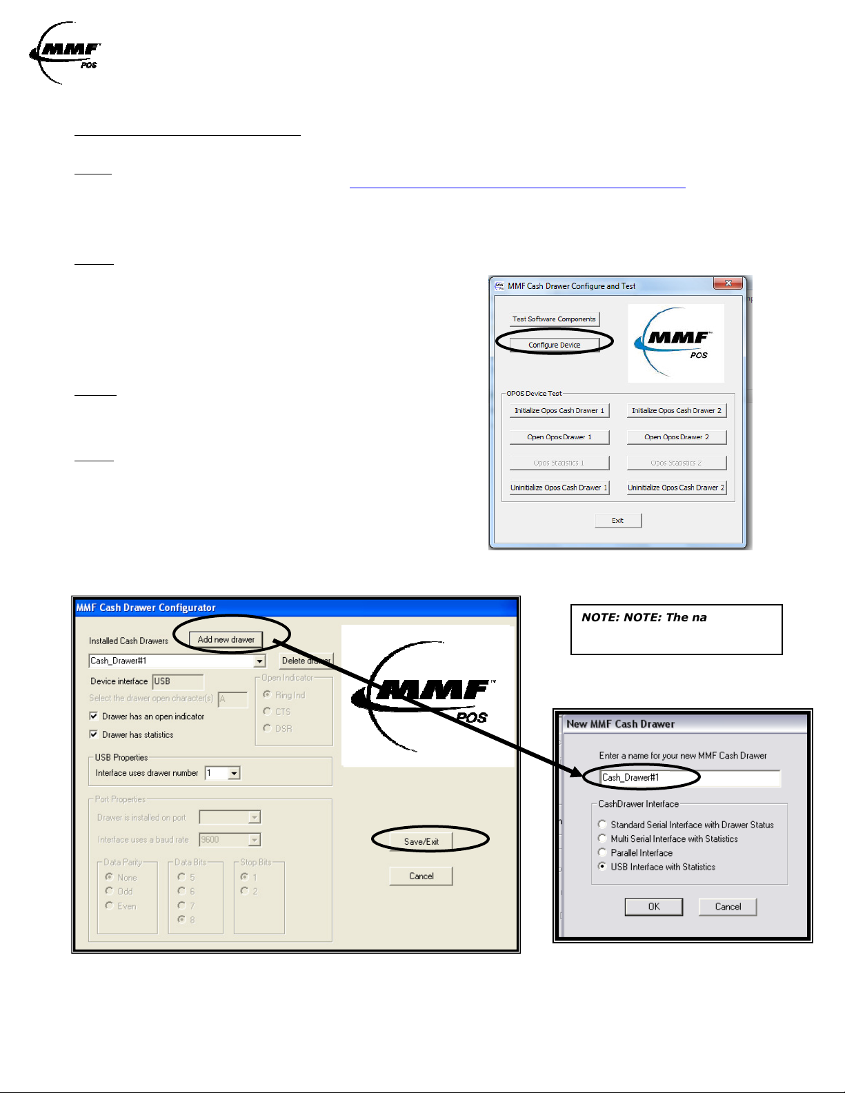
STEP 3
Open the “Configure and Test”
program and click on “Configure Device”. (See Figure 1.2)
STEP 4
To configure drawer - click on “Add new drawer”. A window will appear
asking you to enter a name for your cash drawer, name it
Cash_Drawer#1 (See NOTE). Select the option of “USB Interface
with Statistics” as the Cash Drawer Interface (See Figure 1.3) and click
“OK” to save settings.
NOTE: The name Cash_Drawer#1 is case and character
sensitive. Please type it exactly as shown
FIGURE 1.3
NOTE: NOTE: The name
Cash_Drawer#1 is case and
Approved Date of Revision 7/10/2012 Doc. Instruction Manual
P/N: 531911900
Page 4

USB Interface /USB-HUB Combo Interface Instruction manual / User Guide
STEP 5 FIGURE 1.4
To test drawer - Click on
“Initialize OPOS Drawer 1”
then, click on “Open OPOS
Drawer 1” (See Figure 1.4
the following message will be
displayed:
STEP 6
Click “OK” to the above message and then
manually close the cash drawer.
When the drawer is completely closed the
following message will be displayed:
STEP 7
Click on “Un-initialize OPOS Drawer 1” and the test is complete. Repeat only if necessary.
TROBLESHOOTING TIPS
Make sure the power supply adapter was connected before the USB cable and that LED#4 (GREEN)
is OFF.
Check Dipswitch Setting correlate to the name of the cash drawer. If you decide to change dipswitch
settings, disconnect the power cable and USB cable from the interface, change dipswitch pins and
reconnect all the cables per the steps detailed in the ‘Getting Started’ Section on page one of this
manual.
If installing the OPOS drivers, when adding a new drawer, make sure you selected “USB Interface
with Statistics” as the Interface type.
If installing the OPOS drivers, make sure that under
‘USB Properties’ the number in the dropdown is the
same as the number selected for the drawer on the
dipswitch.
Switch to another USB port in the computer, if necessary.
0
Approved Date of Revision 7/10/2012 Doc. Instruction Manual
P/N: 531911900
Page 5

USB Interface /USB-HUB Combo Interface Instruction manual / User Guide
USB
Interface
to which this declaration relates:
4-
PORT USB HUB FEATURES:
Compliant with USB Specification 2.0 / 1.1
Supports Data Rate: 1.5/12/480 Mbps
4 Downstream Ports
Support split transaction to handle full speed and low speed transaction at downstream
facing ports when Hub controller is working at high-speed mode.
One Transaction Translator per hub and supports four (4) concurrent non-periodic
transactions.
Self or Bus-Powered
Self Power Mode (With Power Supply)
-Connects up to four (4) devices (Any USB Peripheral Device)
-500mA per each USB downstream port – Type A Connectors
Bus Powered Mode (No Power Supply)
-Connects up to four (4) self-powered or low- powered devices
-100mA per each USB downstream port – Type A Connectors
-Only self powered hubs may be connected to hub
Supports Over-Current detection and individual power control
Supports “non-removable” attribution on individual port
USB 4 –PORT HUB SET-UP
STEP 1
Determine if the 5V power supply will be necessary (Self or Bus
Powered) according to the type of peripherals that will connect to
it.
Self Powered Peripherals: Devices which have their own power
supply adapter, and just need the USB connectivity as a
communication medium. Such devices will not need the hub to
be powered by the 5V power supply provided.
Bus Powered Peripherals: Devices which do not have their own power supply adapter and will need 5V or less to
operate. Such devices will need the hub to be powered by the 5V power supply provided.
If not sure, connect the power supply anyway. Plug the small plug tip to the hub power port in the back of the cash
drawer interface as illustrated in Figure 1.5. Plug the power adapter end into a 120 Volt AC Recepticle.
STEP 2
Connect the host cable to the host computer as illustrated in Figure 1.5.
STEP 3
Connect the peripherals to any of the 4 ports available.
NO Drivers or Software necessary for the USB 4-Port Hub
Information
Information
InformationInformation
FCC Statement
FCC Statement
FCC StatementFCC Statement
DECLARATION OF CONFORMITY WITH FCC RULES FOR
DECLARATION OF CONFORMITY WITH FCC RULES FOR
DECLARATION OF CONFORMITY WITH FCC RULES FOR DECLARATION OF CONFORMITY WITH FCC RULES FOR
ELECTROMAGNETIC COMPATIBILITY
ELECTROMAGNETIC COMPATIBILITY
ELECTROMAGNETIC COMPATIBILITYELECTROMAGNETIC COMPATIBILITY
We, MMF Cash Drawer, declare that the product:
System Requirements:
Windows 98/SE/2000/ME/XP/Vista
MAC OS 8.6.1 or above (USB1.1)
5V Power Jack for
4-Port USB HUB
Host CableConnect to
Computer
CE Declaration
CE Declaration
CE DeclarationCE Declaration
Complies with the EMC Directive 89/336/EEC Standard EN55022 (2006), EN55024(1998), EN61000-3-2(1995), EN61000-3-3(2006)
Approved Date of Revision 7/10/2012 Doc. Instruction Manual
P/N: 531911900
Complies with Part 15 of the FCC Rules
This Class ‘A’ Digital apparatus complies with Canadian ICES-003.
Cet appareil numérique de la classe ‘A’ est conforme à la norme
NMB-003 du Canada.
 Loading...