

Page 1
USB Interface with Serial Emulation Interface Instruction manual / User Guide
USB Interface
Supplies & USB Host Cables)
P/N# 641-2575-00: Cash Drawer Power Supply (12V dc)
P/N# 641-25BX-00: USB Host Cable
USB Interface with Serial Emulation
GETTING STARTED:
Download the MMF USB Serial Emulation Driver file from our website by opening the zipped file
Load the MMF USB Serial Emulation Driver into the host computer unit.
Website address: http://www.mmfpos.com/drivers
» Open folder named “MMF USB Serial Emulation Driver”
» Select the filed named “mchpcdc.inf”
» Save in „C:\Program Files‟ or „Desktop‟
Connect the Power Supply (12VDC / .8 Amp)
Plug the small plug tip to the interface power port in the back of the cash drawer interface as illustrated in
Figure 1. Plug the power adapter end into a 120 Volt AC Recepticle.
Always connect the power supply before the USB Cable.
Connect USB Cable
Plug the Type B connector end to the USB Port of the interface as illustrated in Figure 1 and the Type A
Connector to the USB port of the Host Computer.
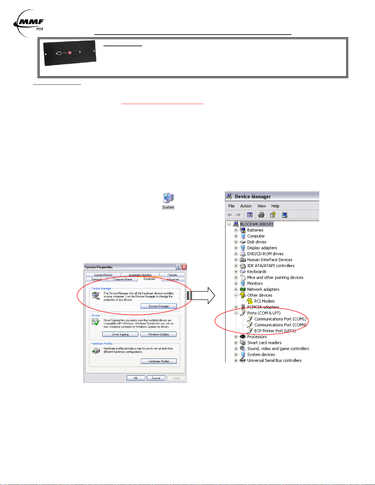
Check which COM Port the Host computer has assigned as the Virtual COM Port
»Go to START Menu
»Select Control Panel
»Click on the System Icon
»Select the Hardware Tab
»Click on Device Manager to view COM Port assigned.
NOTE: On this particular computer COM4 has been
automatically assigned as the virtual com port.
This is the com port designation you will use to
test the interface functionality (STEP 5) and
for your POS software setup.
Test Functionality of Interface
Install OPOS Drivers
MMF POS Date of Revision 7-1-2010 Doc. Serial Emulation Instruction Manual
P/N: 531-9209-00
Follow the steps detailed below for „Serial Emulation Test Procedure‟.
Follow the steps detailed below for „MMF OPOS Drivers Installation‟.
Page 2
USB Interface with Serial Emulation Interface Instruction manual / User Guide
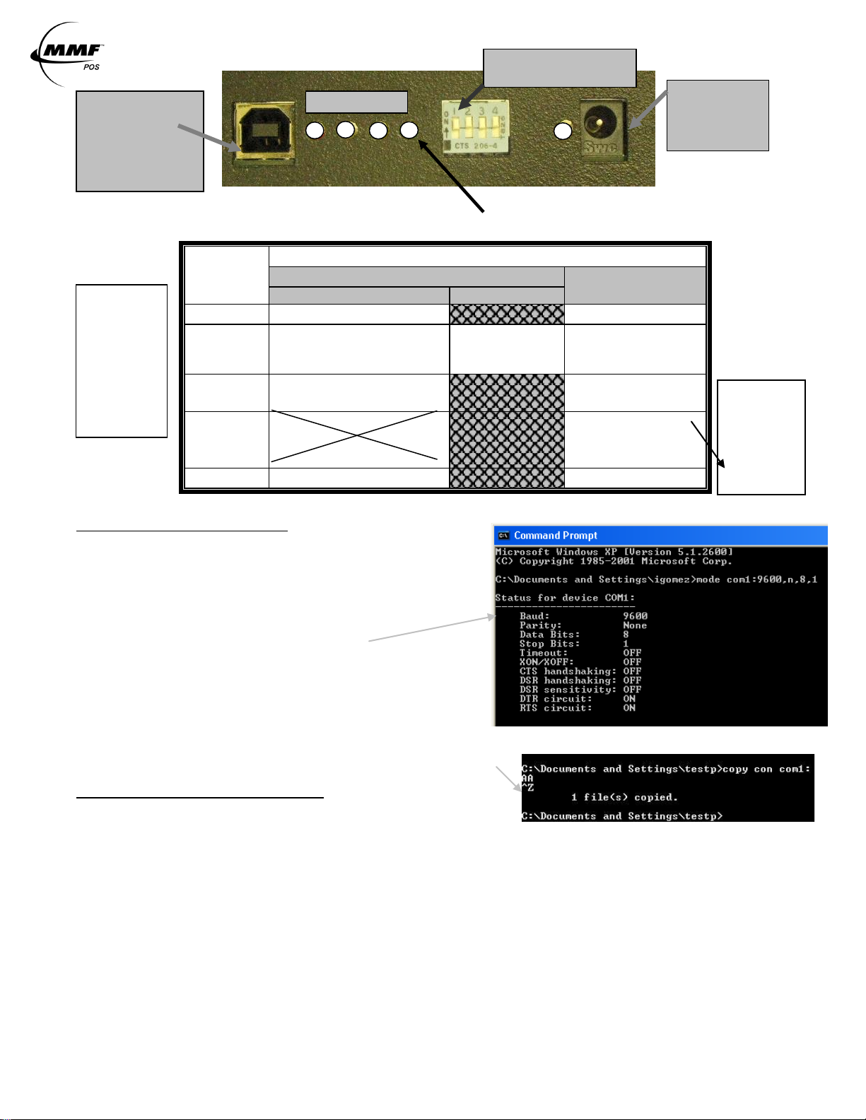
LED
NAME
STATE
ON
OFF
Solid
Intermittent
LED-1
USB Cable Connected
No USB Cable
LED-2
Cash Drawer Closed
USB
Communication
Transmit
Cash Drawer Open
LED-3
Solenoid in position and
ready to kick drawer open
Solenoid kicked
drawer open
LED-4
Port Powered-
Not Recommended
1st:Plug USB Cable
2nd:Plug Power Adapter
Adapter Powered
1st:Plug Power Adapter
2nd:Plug USB Cable
LED-5
Power Supply Connected
No Power Supply
DIP-SWITCH POSITION
Not Used in Serial Emulation
Power Port
Connect 12V DC
Power Supply
Here
USB Port
Port of Cash Drawer
Interface
Connect Type B
Connector of USB
cable Here
4
This light should not be ON at any time
1
2 3 5
NOTE 1
Port Powered:
Draws power
from the
computer,
which will not
provide
enough power
to operate cash
drawer’s latch
mechanism.
NOTE 2:
Adapter
Powered:
Draws power
from the
provided
power supply
adapter.
See
Note 1
FIGURE 1.0
TABLE 2.0
Serial Emulation Test Procedures
Test from Command Prompt:
Go to Start » Programs » Accessories » Command Prompt
Configure the COM port settings by typing:
mode com1:9600,n,8,1 <enter>
(If Device manager created COM4 or any other COM port (1-9) as your virtual
com port, then use that number, i.e. “mode com4:9600,n,8,1”)
The computer should return the following
To test the cash drawer, type the following:
copy con com1: <enter>
A <enter>
Press ‘F6’ Key <enter>
(If Device manager created COM4 or any other COM port (1-9) as your virtual
com port, then use that number, i.e. “copy con com4:”)
The drawer should open at this point and the PC will return the following
An alternative test command program:
Configure the COM port settings by typing:
mode com1:9600,n,8,1 <enter>
(If Device manager created COM4 or any other COM port (1-9) as your virtual com port, then use that number, i.e. “mode com4:9600,n,8,1’)
Type: echo>com1 <enter>
The drawer should open at this point
(If Device manager created COM4 or any other COM port (1-9) as your virtual com port, then use that number, i.e. “echo> com4”)
Close drawer. To open again, Press F3.
Cash drawer should open and computer should reply with: echo>com1
If the drawer fails to open using the test command program, refer to the troubleshooting guide. If drawer
opens successfully, install your POS software or OPOS Drivers, if needed. If the cash drawer fails to open
with the POS Software, contact your software manufacturer for further assistance.
MMF POS Date of Revision 7-1-2010 Doc. Serial Emulation Instruction Manual
P/N: 531-9209-00
Page 3

USB Interface with Serial Emulation Interface Instruction manual / User Guide
MMF OPOS DRIVER V1.9 INSTALLATION
STEP 1
Install MMF OPOS Driver V1.13, available under: http://www.mmfpos.com/drivers
FIGURE 1.2
The user installing the MMF cash drawer software
and configuring the cash drawer devices on Windows
2000 and Windows XP is required to have
Administrator Rights. Once the software is installed,
all users with normal rights can use it.
STEP 2
To install the driver run the file: Setup.exe.
The program will ask you to unzip, click Unzip.
» After download is completed, go to “Start”
Menu
» Go to “All Programs”
» Select the “MMF Cash Drawer” program
» Select the “Configure and Test” program
STEP 3
Open the “Configure and Test” program and
click on “Configure Device”. (See Figure 1.2)
STEP 4
To configure drawer - click on “Add new drawer” (See Figure 1.3). A window will appear asking you to enter a
name for your cash drawer, name it: Cash_Drawer#1 (See NOTE). Select the option of “Standard Serial
Interface with Drawer Status” as the Cash Drawer Interface (See Figure 1.4) and click “OK” to save settings.
FIGURE 1.3
NOTE: The name Cash_Drawer#1 is
case and character sensitive.
FIGURE 1.4
MMF POS Date of Revision 7-1-2010 Doc. Serial Emulation Instruction Manual
P/N: 531-9209-00
Page 4

USB Interface with Serial Emulation Interface Instruction manual / User Guide
STEP 5
Under „Port Properties‟ choose the Port
which Device Manager has assigned as the
Virtual COM Port. In this example, Port 4
was the COM Port assigned.
Then, click on Save/Exit
STEP 6
To test drawer - Click on
“Initialize OPOS Drawer 1”
then, click on “Open OPOS
Drawer 1” (See Figure 1.4
the following message will be
displayed:
STEP 7
Click “OK” to the above message and then
manually close the cash drawer.
When the drawer is completely closed the
following message will be displayed:
STEP 8
Click on “Un-initialize OPOS Drawer 1” and the test is complete. Repeat only if necessary.
MMF POS Date of Revision 7-1-2010 Doc. Serial Emulation Instruction Manual
P/N: 531-9209-00
 Loading...