

Page 1

MMF POS Multi-Serial
Interface
May 1,
Multi-Serial Interface Operator’s Manual
2010
MMF POS
www.mmfpos.com
Phone: 800 769-1954
Page 2
MMF Multi-Serial Interface
INTRODUCTION
The MMF Multi-Serial Interface enables the cash drawer to be controlled by a serial RS-232 output port in the
following configurations:
• Standard serial dedicated; one cash drawer connected to the PC serial port.
• Serial non-dedicated or daisy chain mode; two cash drawers can be connect ed to the s am e serial port or a
serial peripheral can be connected to the cash drawer using the same serial port.
With both the serial non-dedicated and serial ded icated configurati ons it is possible to select via DIP switches the
following options:
Select a specific or random character to open the cash drawer.
Configure RS-232 settings.
Select the open/close drawer status signal for each cash drawer
Compatible with 12VDC powered serial ports.
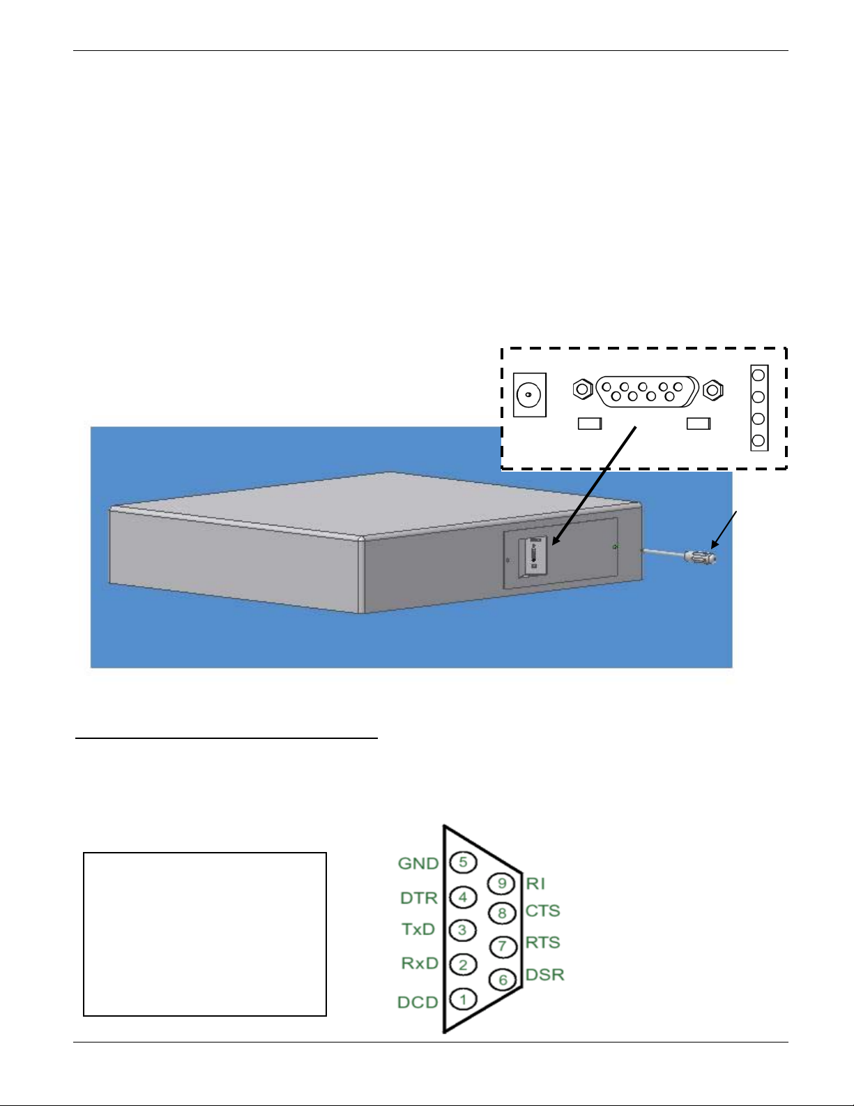
SETTING UP THE CASH DRAWER
Figure 1
RS-232 serial connection
Provides a programmable RS -232 connection to the RS-232 serial port of a host device like a computer or terminal.
Optional cash drawer serial cables and adaptors:
P/N: 2261 99SD9F06 00 -Std. cable DB-9 female to DB-9 male.
P/N: 2261 99ND9F06 00 - Cable to Daisy-Chain 2 cash drawers DB-9 female to DB-9 male and DB-9 male.
P/N: 2261 99ND9FA6 00 - Cable to Dais y-Chain 2 or more cash drawers or to Daisy-chain a ser ial periph eral
such as a printer or other device. DB-9 female to DB-9 male and DB-9 male.
P/N: 2261 99DB9250 00 -Serial Adaptor to convert a DB-9 Male to a DB-25 Female.
PIN 1: DCD - Data Carrier Detect
PIN 2: RXD - Receive Data
PIN 3: TXD - Transmit Data
PIN 4: DTR - Data Terminal Ready
PIN 5: GND - Signal Ground
PIN 6: DSR - Data Set Ready
PIN 7: RTS - Request to Send
PIN 8: CTS - Clear to Send
PIN 9: RI - Ring Indicator
531-8661-00 MMF Multi-Serial Interface Page 1 of 12
Page 3
SW2
SW3
SW1
P2
JP1
SIGPWR
SW3
SW2
SW1
P1
J1
P3
3 2 1
ON
ON
LED Signal Status Panel
LED #4 (top-red) DTR / DSR / DCD Status; LED is ON when there is activity on any of these lines
LED #3 (red) RTS / CTS Status; LED is ON when there is activity on any of these lines
LED #2 (red) Drawer Status. Open / Close inner drawer indicator.
LED #1 (green) Power good when ON solid / Data received when blinking
Supply Voltage Power connector
+12 VDC γ 5% 0.8 A.
Plug required for Power connector:
γ
OD: 5.5mm
ID: 2.1 mm
Length: 8.75 mm
0.1mm - +
γ
0.1mm
γ
0.5mm
DIP Switch settings
To modify the cash drawer settings locate the serial interface module plate on the back of the cash drawer as
shown on Figure 1, remove the two side screws to access the serial PC board and locate the three banks of DIP
switches SW1, SW2 and SW3 as shown in Figure 2.
OFF
OFF
Figure 2
531-8661-00 MMF Multi-Serial Interface Page 2 of 12
Page 4

FUNCTION
1
ASCII Character Bit 0 (LSB)
2
ASCII Character Bit 1
3
ASCII Character Bit 2
4
ASCII Character Bit 3
5
ASCII Character Bit 4
6
ASCII Character Bit 5
7
ASCII Character Bit 6
8
ASCII Character Bit 7 (MSB)
FUNCTION (when ON)
1 2 3 4 5 6 7 8 9
10
1 Loop DTR (pin 4) to DCD (pin 1)
ON
OFF
2
Loop DTR (pin 4) to DSR (pin 6)
OFF
ON
OFF
3
Loop CTS (pin 8) to RTS (pin 7)
ON
OFF
OFF
4
Receive Drawer-Open data input on TXD (pin 3)
ON
OFF
OFF OFF
5
Receive Drawer-Open data input on RXD (pin 2)
OFF
ON
OFF 6 Receive Drawer-Open data input on CTS (pin 8)
OFF
OFF
OFF
ON
OFF
7 Send Drawer-Status output on CTS (pin 8)
OFF
OFF
ON
OFF
OFF
8
Send Drawer-Status output on RI (pin 9) -see JP1
OFF
ON
OFF
9
Send Drawer-Status output on DSR (pin 6)
OFF
OFF
OFF
ON
10
Re-Transmit Drawer-Open data signal on TXD (pin 3)
OFF ON
Switch 1
When the indicated Switch is ON, all other specified Switches in the same column must be OFF
SW1
SW1 CONFIGURATION CONSTRAINTS
POS
JP1 when SW 1-pos 8 is in the O N pos ition, jum per JP1 mus t be place d in the SIG posit ion (j umper ac ross pins
1 and 2 of JP1).
JP1 must be placed on the PWR position (jumper across pins 3 and 2 of JP1) when recei ving power via pin 9
from a PC powered serial port.
Switch 2
SW2 Functions only apply when the controller is set to "Smart Mode" (SW3-1 = ON)
SW2
POS
531-8661-00 MMF Multi-Serial Interface Page 3 of 12
Page 5

FUNCTION
1
Smart Mode (ON) / Dumb Mode (OFF) Select
2
Drawer Status Polarity (OFF = Norm / ON = Invert)
3
Pulse Count 0
4
Pulse Count 1
5
Reserved
6
Reserved
7
Reserved
8
Reserved
Pos 4
Pos 3
Number
P-Cnt 1
P-Cnt 0
of Pulses
OFF
ON
4 Pulses
OFF
OFF
4 Pulses
ON
ON
3 Pulses
ON
OFF
2 Pulses
FUNCTION
2
Drawer Status Polarity (OFF=Norm / ON=Invert)
3
Baud Rate
4
Baud Rate
5
Baud Rate
6
Parity Type (OFF = Even / ON = Odd)
7
Parity Enable (ON = Parity Enabled)
8
Number of Data Bits (OFF = 7 Bits, ON = 8 Bits)
Pos 5 Pos
4
Pos
3
Baud Rate
OFF
OFF
OFF
300
OFF
OFF
ON
600
OFF
ON
OFF
1200
OFF
ON
ON
2400
ON
OFF
OFF
4800
ON
OFF
ON
9600
ON
ON
OFF
19200
Switch 3
“Dumb Mode” any open character based on the number of pulses within that ASCII character will open the cash
drawer.
SW3 - "Dumb Mode"
POS
The above SW3 Functions only apply when the controller is set to “Dumb Mode” (SW3-1 = OFF)
“Smart Mode” open character and RS-232 settings are pre-selected.
SW3 - "Smart Mode"
POS
The above SW3 Functions only apply when the controller is set to "Smart Mode" (SW3-1 = ON)
Parity / 7 D ata Bits Note: When the number of data bits is set to 7 (SW2-8 = OFF) parity must
(SW3-7 = O N). Setting the number of data bits to 7 while parity is disabled will result in an invali d mode. If the
controller is set to this mode, LED #1 (green) and LED #2 (red) will blink to indicate the invalid condition.
PULSE COUNT SELECT SW3
BAUD RATE SELECT
be Enabled
531-8661-00 MMF Multi-Serial Interface Page 4 of 12
Page 6

Serial
SW2
SW3
SW1
P2
JP1
SIGPWR
SW3
SW2
SW1
P1
J1
P3
Factory Default
SW1
SW2
SW3
Connect
12V
1 10
CONFIGURATION EXAMPLES
Factory Default –This standard configuration is set so that any on e (1) ASCII character wil l open the cash
drawer and the RS-232 settings are auto-detected auto matically by the cash drawer.
port
Serial cable: MMF P/N: 2261 99SD9F06 00
CASH DRAWER
power
supply.
ON
OFF
Settings:
SW 1 Receive Open character on TXD and send drawer-status outp ut on RI.
SW 2 Open character is: Any ASCII character with at least 2 pulses. Normally any ASCII from 0-dec
to 127-dec will have at least two pulses.
SW 3 Dumb mode, serial board auto-detects the PC or terminal RS-232 settings like, the baud rate, data
bits, and parity.
1 On 1 On 1 OFF
2 OFF 2 OFF 2 OFF
3 OFF 3 OFF 3 OFF
4 On 4 OFF 4 On
5 OFF 5 OFF 5 OFF
6 OFF 6 OFF 6 OFF
7 OFF 7 On 7 OFF
8 On 8 OFF 8 On
9 OFF
10 OFF
JP1 : place jumper across pins 1 and 2
531-8661-00 MMF Multi-Serial Interface Page 5 of 12
Page 7

TEST PROCEDURE
Factory Default – Any ASCII character will op en drawer and RS-232 sett ings are auto-detecte d automatically
by the cash drawer.
Test from DOS:
1.- Configure theCOM port settings
by typing:
MODE com1:9600,n,8,1
The computer should
return the following
2.-To test the cash drawer t ype:
copy con com1: <enter>
A <enter>
F6 <enter>
The drawer should open and the
PC will return the following
Test from Windows:
Factory Default – Any ASCII character will open drawer and RS-232 settings are auto-detected.
1.- INSTALL MMF OPOS DRIVER –V1.9, available under:
www.mmfcashdrawer.com / Tech Support / Drivers
The user installing the MMF cash drawer software and configuring the cash drawer devices on Windows 2000
and Windows XP is required to have Administrator Rights. Once the software is installed, all users with normal
rights can use it.
To install the driver run the file: Setup.exe. When the installation is complete, a start menu item under the
‘Programs’ folder will have entries for both the:
-Configure and Test
- OPOS Test
2.- Open the “Configure and Test “
program and configure the screen
with the following settings:
3.- Click on “Configure Device”
531-8661-00 MMF Multi-Serial Interface Page 6 of 12
 Loading...