

Page 1
Transaction Terminal Stands (P/N:225-7582-04 & P/N:225-7583-04)
Quick Installation Instructions
Designed for Ingenico® models i6550 & i6580 mounting patterns
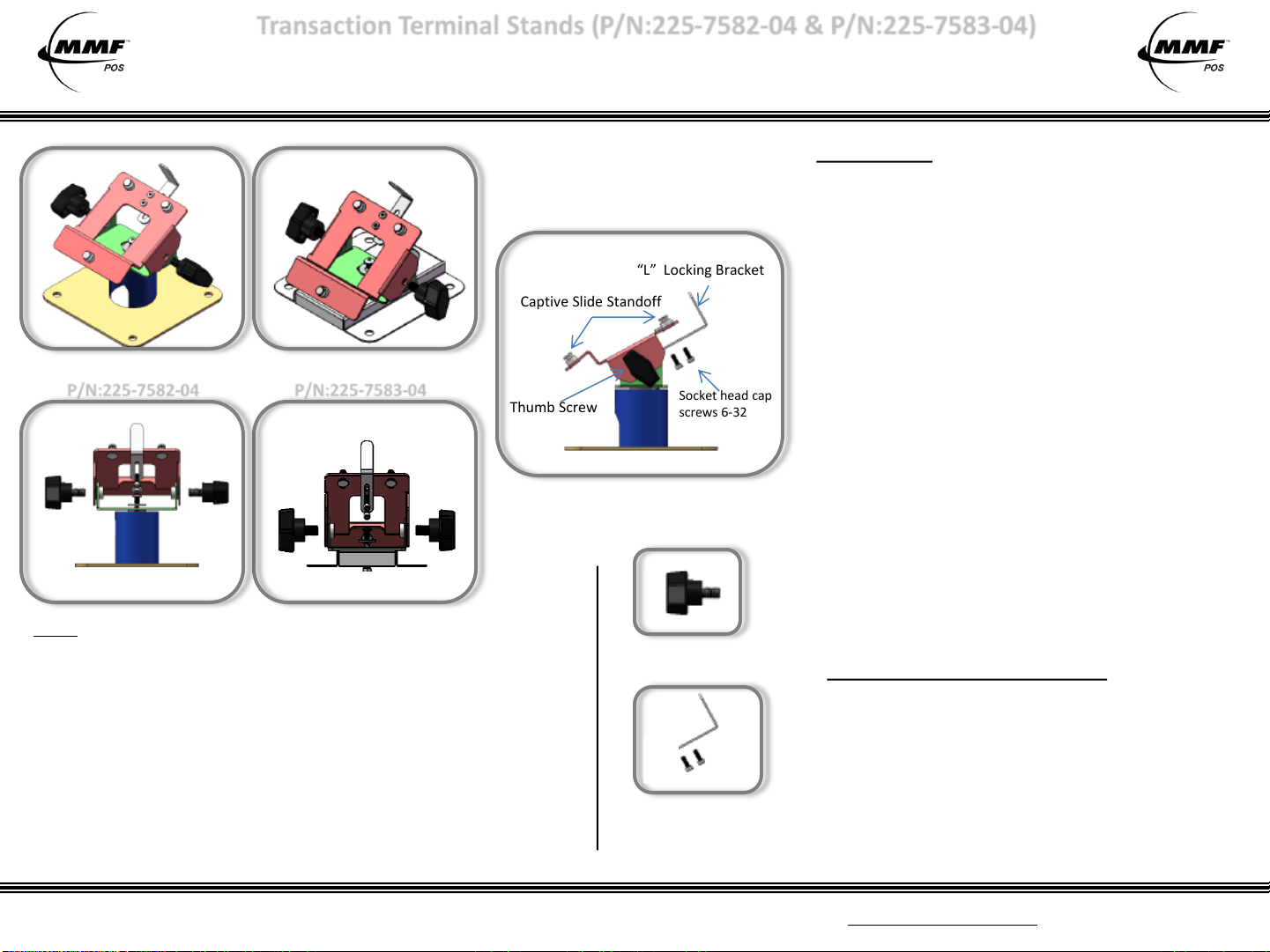
Front View Front View
Captive Slide Standoff
2” Height Stand
P/N:225-7582-04
Back View Back View
SPECS
Rotation: 180°around display pole
Overall Height & Tilt Adjustment (without Terminal) :
• 2” Height Stand: at 30⁰ Tilt= 4” high / at 45⁰ Tilt= 4 ½” high
• Fixed Height Stand: at 30⁰ Tilt= 3 1/8” high
Pole Diameter: 2” (Applies to 2” Height Stand)
Base Dimensions: 5” x 5”
Construction: 18 gauge Steel
Finish: Textured powder coat
Cable Management: Designed with openings for easy and convenient
cable access and routing.
Color: Black
For parts and/or additional accessories, contact your supplier or visit our website at http://www.mmfpos.com
Fixed Height Stand
P/N:225-7583-04
Thumb Screw
“L” Locking Bracket
Socket head cap
screws 6-32
Basic Overview
Note: Images are not to scale.
Thumb Screw
P/N: 225-76140-04
Kit:
One (1) “L” Locking Bracket
Two (2) Socket head cap screws 6-32
Re p l a c e m e n t P a r t s
One (1) Allen wrench
P/N: 225-76903-04
INSTALLATION
1. Remove stand from packaging box. Firmly secure the
base pole by bolting four (4) screws through the base
plate to a flat counter surface.
2. Loosen up (but, do not remove) the Socket head cap
screws from the “L” Locking Bracket using the Allen
Wrench provided in the kit until it can slide up & down
easily.
3. Mount payment terminal to stand by aligning and
hooking in place the mounting holes of the terminal to
the Captive Slide Standoff on the stand.
4. Secure the terminal by sliding and tightening the “L”
Locking Bracket located in the back of the stand
using the Allen Wrench provided in the kit.
5. Secure the stand’s tilt adjustment by tightening the
two side thumb screws on the mounting plate on
each side of the stand.
6. Guide cable connections down and out through the
bottom opening.
7. Make cable connections as needed.
TOOLS AND HARDWARE REQUIRED
• One (1) Allen Wrench is included with kit to adjust the
Socket head cap screws (6-32) for the “L” locking bracket.
• NO other hardware or tools are included for mounting
stands to a surface. Hardware will need to suit your
specific desktop or platform thickness.
• Phillips Head Screwdriver or power drill will be required
to mount stand to surface (if necessary).
TTS-01 Inst. Sheet (12-02-2010)
COPYRIGHT BY MMF POS
COMPANY, WHEELING, IL
 Loading...