

Page 1
PoweredUSB Interface Board Instruction manual / User Guide
SWITCH SETTINGS
DRAWER
0 1 2 3 4 5 6
7
DIP-SWITCH
SW1
OFF
SW2
OFF
SW3
OFF
SW4
OFF
OFF
OFF
OFF
OFF
OFF
OFF
OFF
Reset
Statistics
SW4
ON
ON
ON
ON
ON
ON
ON
ON
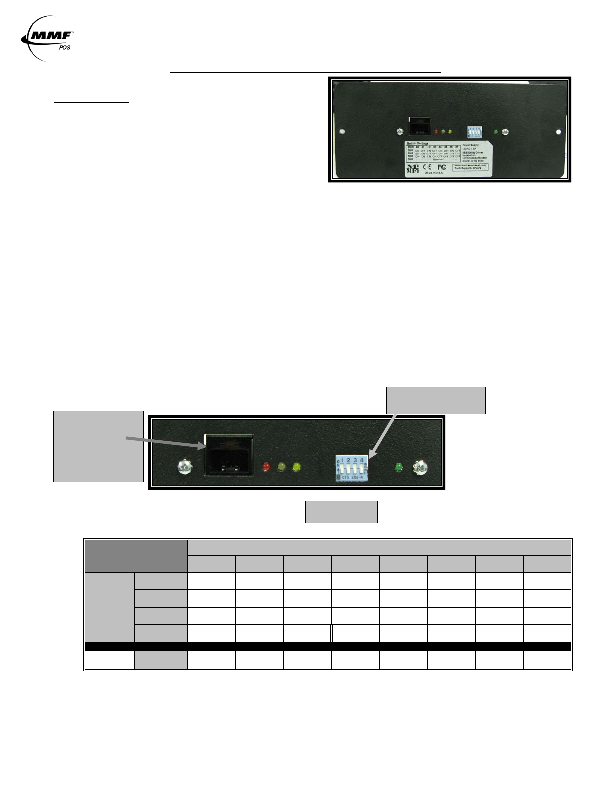
DIP-SWITCH POSITION
Default Setting: Drawer 7
USB Port
1
2
3
4
LEDS
PoweredUSB Interface Board
COMPONENTS
2261998PWRUSB-XX – PoweredUSB
Interface KIT
Part# 641-25CJ-00- PoweredUSB Cable
INSTALLATION
Select Cash Drawer Number
The MMF POS USB Interface Board is factory defaulted to rec ognize the first cash
drawer to be installed as drawer number seven (7), see Figure 1.0 Dip-Switch Pos ition
(Default Setting). If us er decid es to as s ign another drawer number , plea s e follow the
pin configuration illustrated in SWITCH SETTINGS Table 1. 0 or label attached to the
interface for correct pin orientation.
Connect the 12V PoweredUSB Rated Cable to the hos t (12VDC / .8 Amp)
Plug the 2x4 Molex Latch-n-Lock connect or end to the USB Port of the interface and the
12V Connector (Color:Teal) end to the corresponding 12V jack PoweredUSB port of the
Host Computer or PoweredUSB Hub.
Test Functional ity of In terfa ce
Follow the steps d eta iled be low f or ‘US B Test U tility In stalla tion’ .
Install OPOS Drivers (If Required)
Follow the steps d eta iled be low f or ‘MM F OPO S Drive rs Ins tallati on’.
NOTE: Do not assign two (2) USB interface cash drawers within the same system with the same cash drawer number.
FIGURE 1.0
Port of Cash Drawer
Interface
Connect Type B
Connector of USB
cable Here
TABLE 1.0
ON OFF ON OFF ON OFF ON
ON ON OFF OFF ON ON OFF
ON ON ON ON OFF OFF OFF
NOTE: OFF is when pins are facing dow n (↓). ON is when pins are facing up (↑).
NOTE: ONLY place SW4 on the ON Position if you will like to reset the statistics s tor ed and reported though
the OPOS Drivers.
Approved Date of Revision 5/1/2010 Doc. PoweredUSB
Instruction Manual
Page 2
PoweredUSB Interface Board Instruction manual / User Guide
STATE
ON
OFF
Solid
LEGEND
TABLE 2.0
LED
NAME
COLOR
LED-1 Red 5V Power (for PCB) ON No 5V Power (for PCB)
LED-2 White Cash Drawer Closed Cash Drawer Open
LED-3 Yellow
Solenoid in position and
ready to kick drawer open
Solenoid kicked drawer
open
LED-4 Green 12V Power (Solenoid) ON No 12V Power (Solenoid)
FIGURE 1.1
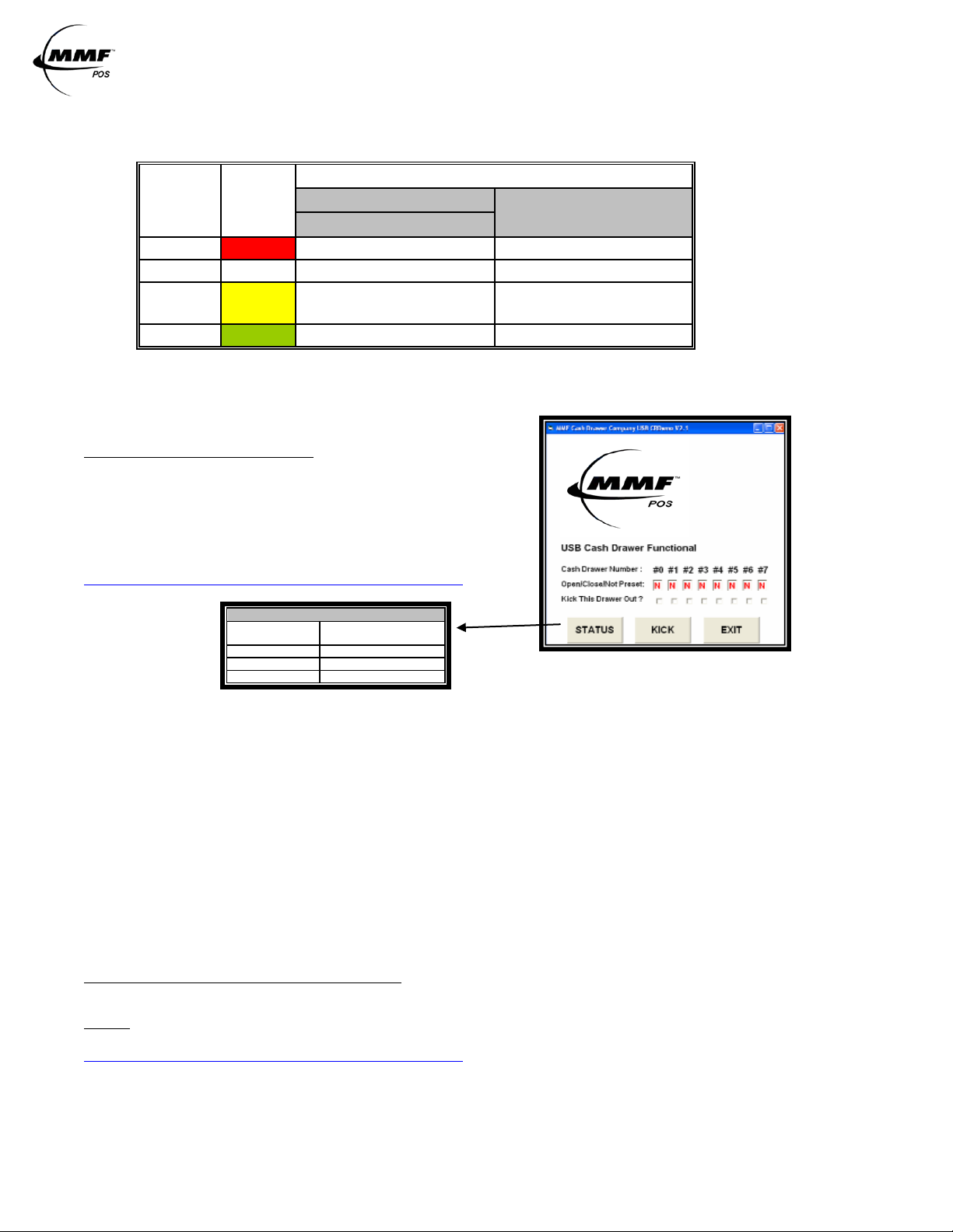
USB TEST UTILITY INSTALLATION
MMF Cash Drawer Company USB CRD emo
A CD with the utility drivers and test utility (S ee F igure 1.1) is
included with the cash drawer. The drivers and test could
also be found by logging on to:
http://www.mmfpos.com/drivers
Action
Not Present N
Closed C
Opened O
Result under
Assigned Drawer #
Download the MMF USB Driver and Test Utility file by opening the zipped file.
» Cl ic k o n the “Setup” I con
» Cl ic k o n “Run”
» Fol lo w thr ough the automatic setup
» Af te r dow nload is completed, go to “Start” Menu
» Go to “All Pr og rams”
» Se l ect the “MMF Cash Drawer Company USB CRDemo” program
» Open folder named “MMF USB_Setup”
Click Status, a r e su lt letter character (N/C/O) should appear in the result box under the
cash drawer number given to the unit by setting the dip switch (Step 1-G ettin g Star ted)
Make sure cash drawer is closed and the letter ‘C’ appears in the result box.
Click ‘Kick’ to open the cash drawer, the letter ‘O’ should n ow appear in the result box .
Repeat if necessary
MMF OPOS DRIVER V1.9 INSTALLATION
STEP 1
Install MMF OPOS Driver V1.11, available under:
http://www.mmfpos.com/drivers
The user installing the MMF cash drawer software and configuring the cash drawer devices on Windows 2000 and
Windows XP is required to have Administrator Rights. Once the software is installed, all users with normal rights
can use it.
Approved Date of Revision 5/1/2010 Doc. PoweredUSB
Instruction Manual
 Loading...