


Instruction Manual
Manfred Weber
Metra Mess- und Frequenztechnik in Radebeul e.K.
Meissner Str. 58 - D-01445 Radebeul
Tel. +49-351 836 2191 Fax +49-351 836 2940
Email: Info@MMF.de Internet: www.MMF.de
Vibration Meter
VM22

Published by:
Manfred Weber
Metra Mess- und Frequenztechnik in Radebeul e.K.
Meißner Str. 58
D-01445 Radebeul
Tel. +49-351-836 2191
Fax +49-351-836 2940
Email Info@MMF.de
Internet www.MMF.de
Note: The latest version of this manual can be found at
http://www.mmf.de/product_literature.htm
Specification subject to change.
© 2012 Manfred Weber Metra Mess- und Frequenztechnik in Radebeul e.K.
Full or partial reproduction subject to prior written approval.
Feb/ 17

Contents
1. Purpose..................................................................................................................3
2. Function................................................................................................................. 3
2.1. The Sensor......................................................................................................3
2.2. The Measuring Instrument..............................................................................4
3. The Measurement Procedure.................................................................................4
4. The Batteries.......................................................................................................... 5
4.1. Inserting the Batteries..................................................................................... 5
4.2. Switching On and Off.....................................................................................6
4.3. Battery Display and Battery Type...................................................................7
4.4. Shut-off Timer................................................................................................7
5. Preparation of Measuring Points............................................................................8
5.1. General Information on Measurement Point Choice.......................................8
5.2. ISO 10816-1 Recommendations.....................................................................8
5.3. VMID Measurement Point...........................................................................10
5.3.1. How the VMID Measurement Point Functions.....................................10
5.3.2. Mounting the VMID Measurement Point..............................................10
6. Measurement........................................................................................................11
6.1. Measurement Value Display.........................................................................11
6.2. Measurement Point Detection.......................................................................11
6.2.1. Reading the VMID Data with the VM22...............................................11
6.2.2. Entering the Measurement Point Text...................................................12
6.2.3. Deleting Measurement Point Data.........................................................13
6.3. Saving Measurands.......................................................................................13
7. Viewing Saved Measurement Data......................................................................14
7.1. Graphical Trend Display...............................................................................14
7.2. Viewing Saved Measurement Values............................................................15
7.3. Deleting all Measurement Data....................................................................15
8. Measurement Evaluation.....................................................................................15
9. Setting the Date and Time....................................................................................18
10. Calibration.........................................................................................................19
11. Sensor Check.....................................................................................................21
12. Reset Key...........................................................................................................21
13. Connection to a PC............................................................................................21
13.1. Device Driver............................................................................................. 21
13.2. VM2x Measurement Database....................................................................22
13.3. Firmware Update........................................................................................23
14. Technical Data...................................................................................................25
Limited Warranty....................................................................................................27
Appendix: Warranty
Declaration of CE Conformity
1
2
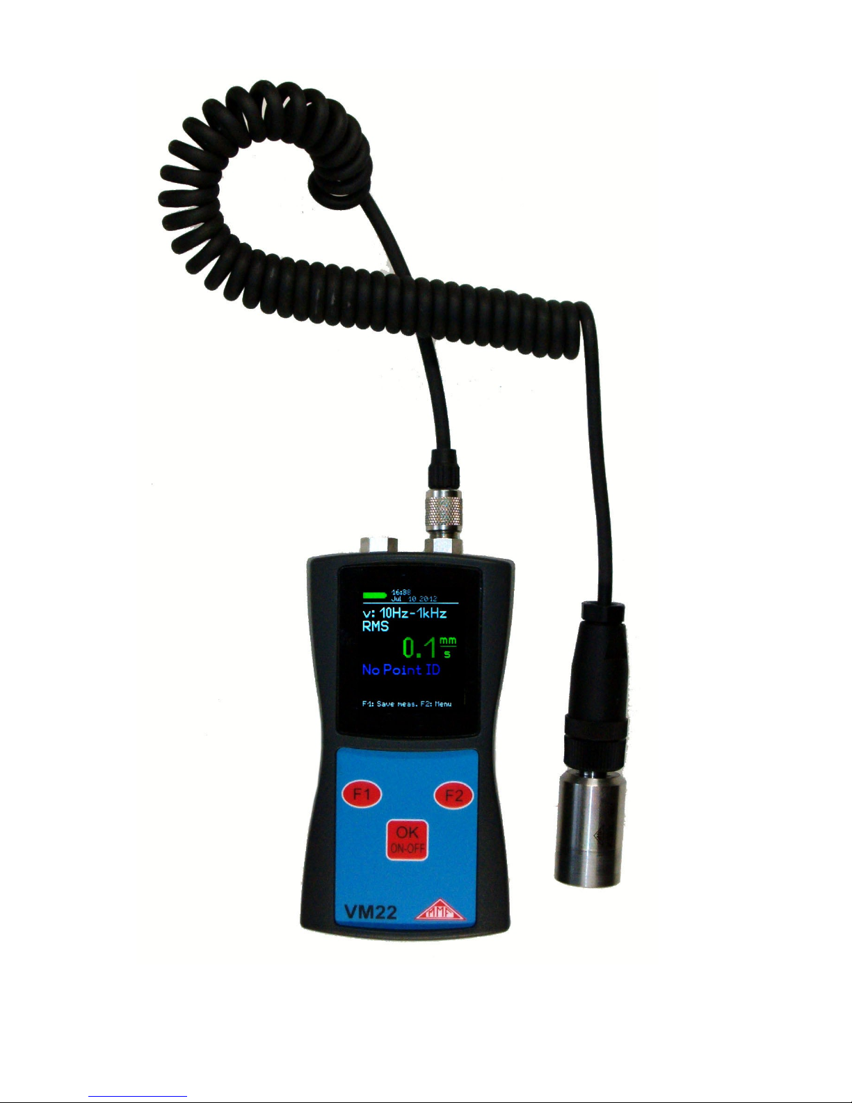
Figure 1: VM22 with sensor

Thank you for choosing a Metra Vibration Measurement Instrument!
1. Purpose
The VM22 has been developed, particularly, for the measurement and monitoring of
vibrations on rotating machines. The purpose of such measurements is to monitor
the condition of the machine in order to avoid unscheduled shut-down. Furthermore
vibration measurement is carried out prior to the distribution of new machinery and
subsequently to repair with a view to quality control and the issuing of product guarantees.
The basis for successful machine condition monitoring is the measurement of the vibration severity over a longer period of time. Measurements are taken at regular intervals of time and recorded.
The VM22 measures and records vibration velocity, also known as vibration severity, at a frequency range of 10 to 1000 Hz. The VM22 specification corresponds to
the ISO 2954 regulations and is suitable for, among other things, the measurement
of machine vibrations on machines with a nominal speed at or above 120 min-1, in
accordance with ISO 10816.
An external piezoelectric accelerometer is used as the sensor, and is provided to gether with the instrument. The VM22 is fitted with an electronic measurement
point detector (VMID) which enables it to take routine measurements of a large
number of measurement points very effectively. A software package for transferring
the measurement data to a PC is also available from Metra.
In the common hierarchy of condition monitoring the VM22 is equivalent to “Level
1”. This represents the long term monitoring of parameters with low technical and
personnel requirements.
For fault detection (“Level 2”), as a further step, spectral diagnostic measurements
are taken, which require a large degree of expertise and sophisticated measurement
technology.
In the development of the VM22 value was placed on simple operation and maintenance requirements, which enable trained personnel to operate the instrument without the need of being specially qualified.
2. Function
2.1. The Sensor
The VM22 operates with a piezo ceramic shear accelerometer. Piezoelectric vibration transducers are characterized by high precision and resolution with great robustness. The accelerometer of the VM22 has an integrated electronic circuit for imped ance conversion in accordance with the IEPE standard. At the base of the sensor a
magnet has been integrated for mounting to the measurement point. In the center of
the magnet there is a contact point from which the identification number can be
read. The measurement point ID is saved in the available VMID measurement
points.
The coupling surface is protected by a metal cap which attaches to the sensors magnetic base.
3
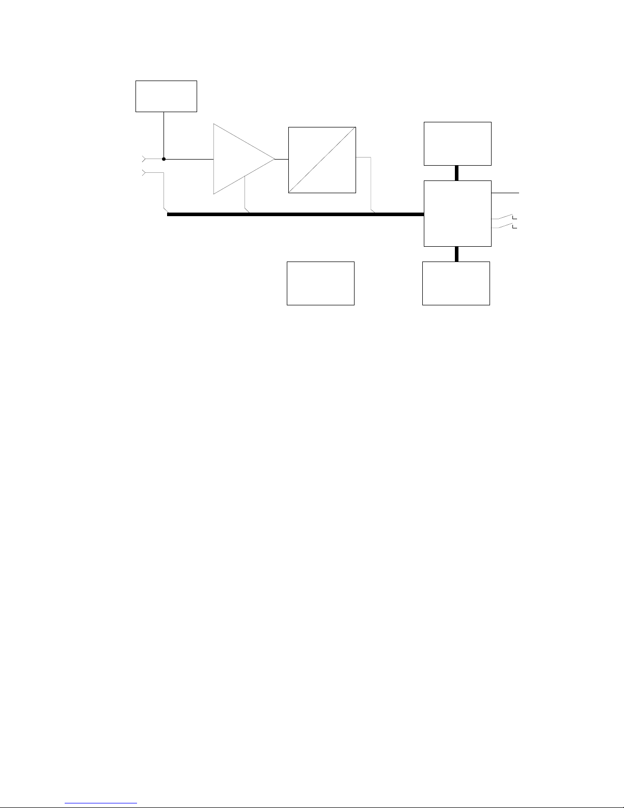
2.2. The Measuring Instrument
2 shows the block diagram. The VM22 supplies the IEPE Sensor with 2 mA constant current. At the sensor output, a vibration acceleration proportional AC voltage
arises, which is amplified in the instrument to produce an optimum level. The gain
switch-over takes place automatically. The subsequent analog/digital converter is a
Sigma-Delta converter with 24 bit resolution.
Further signal processing, such as filtering, integration (for calculating velocity from
acceleration) and RMS is carried out in the micro controller. The micro controller
also controls the graphic display, the USB communication and the storing of measurements.
3. The Measurement Procedure
Measuring vibration velocity is a common procedure for assessing the running smoothness of rotating machines. Vibration velocity, commonly known as vibration severity, is a
measurement of the energy expenditure of occurring vibrations. Vibrations are caused by
rotational imbalances, for example as a result of loose screws, bent parts, worn or slack
bearing clearance or dirt residues on fan blades. Often several factors have a mutually reinforcing effect. Besides rotary machines, the measurement procedure is also suitable for
reciprocating machines.
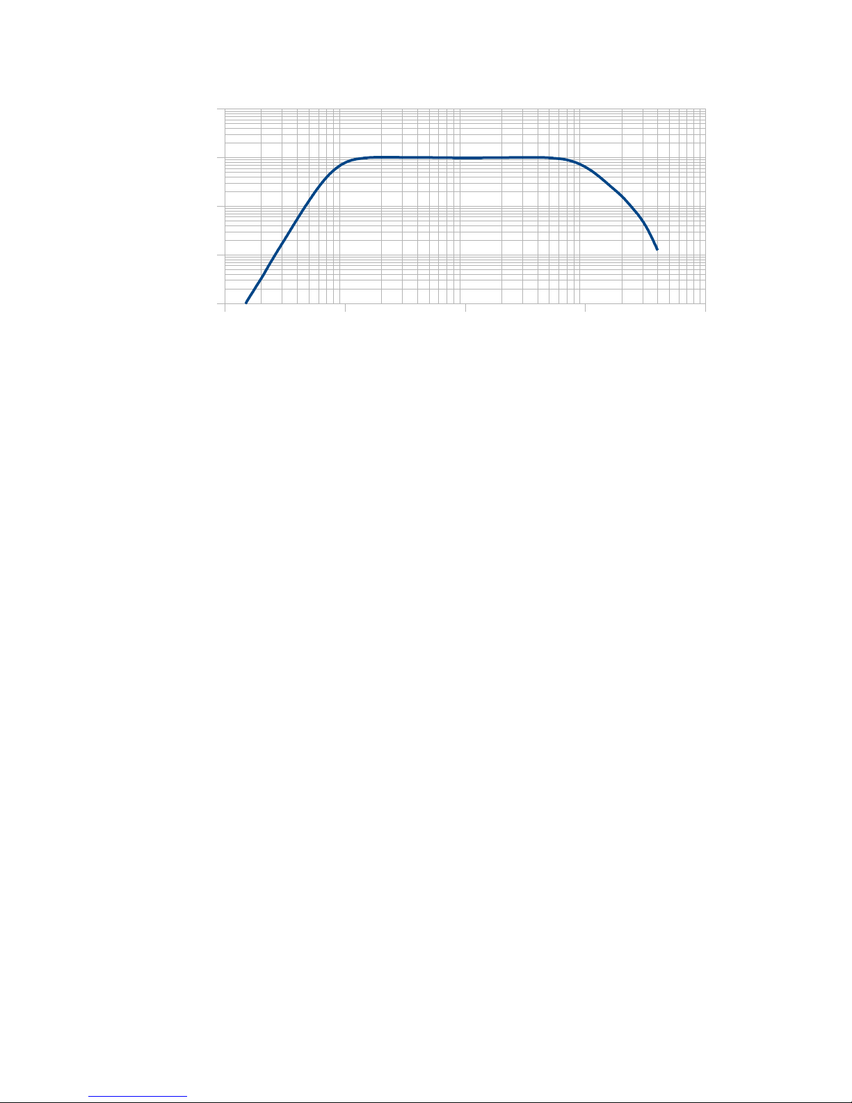
The specifications of vibration velocity measuring instruments are described in
ISO 2954. In the ISO 2954 a band filter for the vibration velocity of 10 to 1000 Hz is defined. The corresponding VM22 frequency response graph can be viewed in 3.
The displayed value of the vibration severity is the true RMS.
4
Figure 2: Block Diagram
IEPE
supply
Progr.
amplifier
A
D
Micro
controller
Display
Memory
Keys
Sensor
ID
USB
Power
supply
4. The Batteries
4.1. Inserting the Batteries
The VM22 is supplied by three alkaline standard cell type AAA (LR03) batteries.
NiMH batteries (HR03) may also be used. The minimum energy requirement of the
VM22 enables maximum utilization of the batteries.
Attention: Please switch the instrument off before changing the batteries. When
switched off, the contents of the memory are stored for a few minutes, without need
of the batteries, and the internal clock continues to run. If the batteries are removed
when the instrument is switched on or if they remain in the instrument until the batteries have been completely discharged, the device will perform a new start once the
batteries have been changed. Following a 'new start' the date and time will need to
be newly set. Further settings as well as the saved measurands, are stored without
need of the batteries.
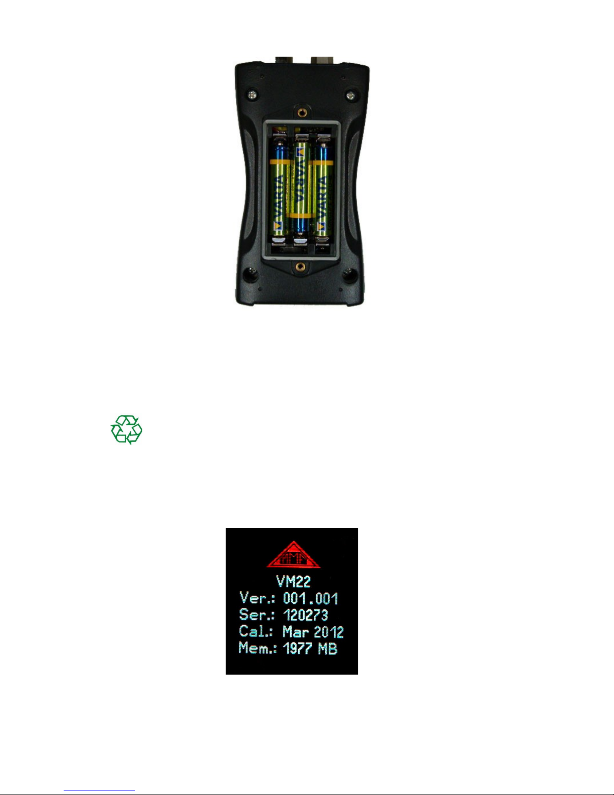
To insert the batteries, remove the two screws from the back cover of the device and
open the battery compartment (4). When inserting the batteries, please ensure that
their polarity is correct, (see the engraved markings inside the compartment).
5
Figure 3: The Frequency Response of theVM22
1 10 100 1000 10000
0,001
0,010
0,100
1,000
10,000
Hz
mm /s
Important:
• Always use three batteries of the same type and same date of manufacture.
• Remove old batteries from the instrument, and take out the batteries if the instru-
ment will not be used for a long period of time. Otherwise leaking battery acid
may cause severe damage to the instrument.
Please use your local collection point to dispose of batteries.
Batteries do not belong to the household waste.
4.2. Switching On and Off
The instrument is switched on by a short press of the ON-OFF button. A start screen
will be shown on the display for 3 seconds. (5).
This displays the hardware version number (the 3 digits before the point) and the
software version number (the 3 digits after the point) followed by the serial number
6
Figure 4: Battery Compartment
Figure 5: Start Screen
corresponding to the type label. The month and year of the last calibration are dis played (cf. Section 10) along with the memory capacity.
By pressing the ON-OFF button again the VM22 switches itself off. In addition, the
instrument has an automatic shut-off timer for saving the battery power (see cf.
Chapter 4.4).
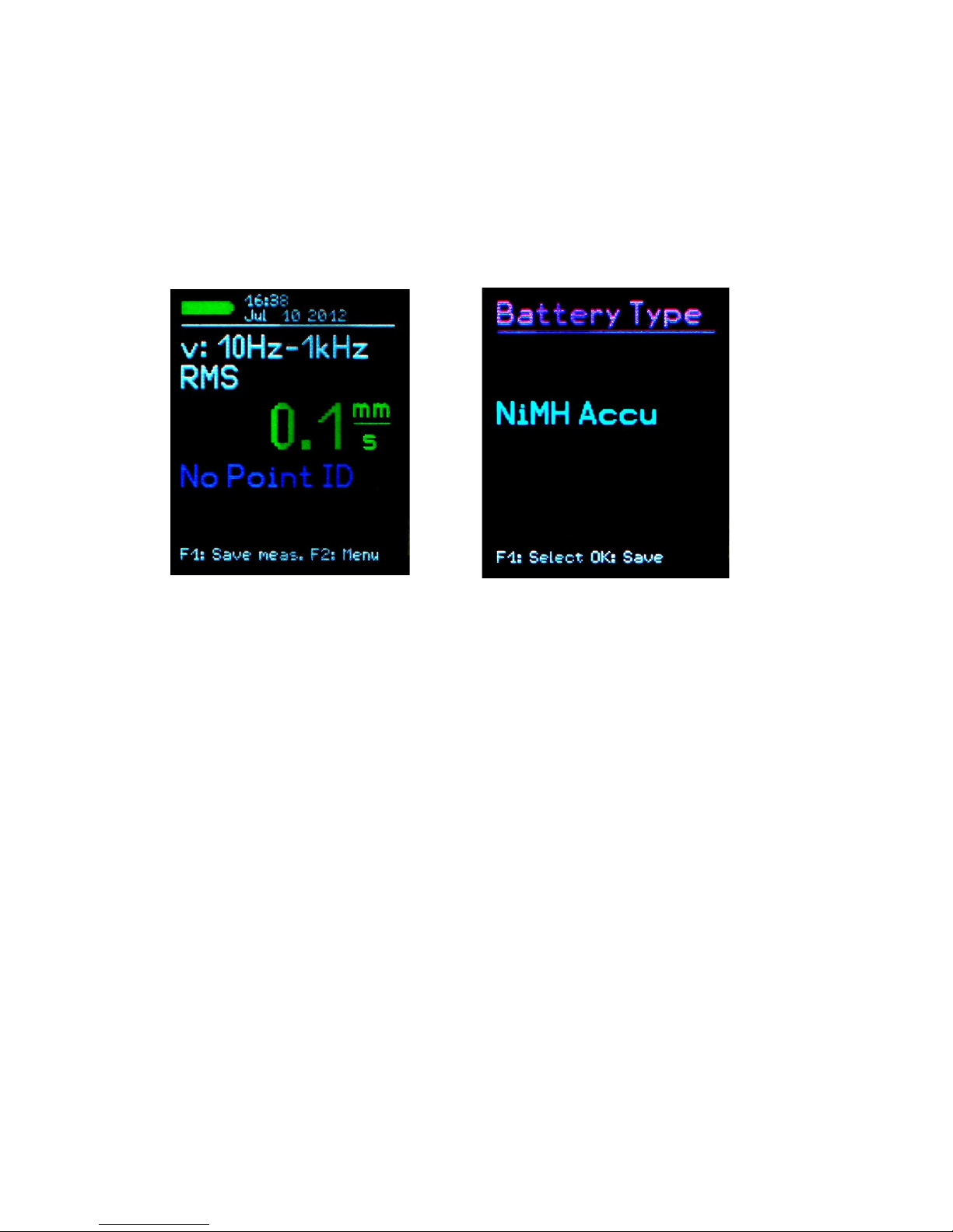
4.3. Battery Display and Battery Type
In the upper left corner of the VM22 display there is a battery level indicator ( 6).
When the green battery symbol is full, the battery is fully charged.
While non-rechargeable batteries have a cell voltage of 1.5 V, NiMH rechargeable
batteries deliver only 1.2 V per cell. The VM22 battery indicator can be adjusted to
both voltages. To adjust the voltage remove the sensor from the VMID and press F2
to open the main menu. Here the battery type can be changed by pressing F1 to
scroll down to the menu option 'Instrument Settings' and then pressing OK. Within
the sub-menu select “Battery type” by following the same instructions as before (7)
and then by pressing F1 scroll between F1 “Alkaline” (non-rechargeable, 1.5 V) or
“NiMH Accu” (rechargeable, 1.2 V). Confirm your choice by pressing OK and exit
the menu by pressing F2 repeatedly.
If the power supply drops below 3.3 V when using alkaline batteries or below 3 V
with rechargeable batteries, the battery indicator becomes red. Further measurements
can be taken until the power supply reaches 2.8 V in keeping with the instrument
specifications. At this point the battery level indicator is completely empty and the
instrument switches itself off automatically.
If the VM22 is connected to a USB port, it will be supplied by the USB voltage in
order to spare the batteries. In this case, “External” is displayed on the screen in stead of the battery level indicator.
4.4. Shut-off Timer
The VM22 has a shut-off timer to help prolong the battery operating life. To set the
shut-off timer, remove the sensor from the VMID and press F2 to open the main
menu. From the main menu scroll down to the sub-menu option “Instrument Settings” by pressing F1 and OK. Here the menu option “Shut-off timer” can be se-
7
Figure 6: Battery indicator upper left
Figure 7: Select battery type

lected by pressing F1 and the timer duration options of 1, 5, 15 and 60 minutes can
be selected, alternatively to deactivate the switch off timer select “none”. The automatic switch off timer starts to run after the last press of a button. If a button is
pressed then the timer restarts and counts down again according to the duration se lected.
5. Preparation of Measuring Points
5.1. General Information on Measurement Point Choice
When monitoring machines it is important to take measurements under the same operating conditions, at the same measurement point. Choosing the suitable measurement point is therefore decisive.
Where possible, qualified staff experienced in machine monitoring should be called
upon.
It is generally advisable to record machine vibrations near to their source. This helps
to reduce distortion of the measuring signal to a minimum when it is being carried
through transmission parts. Suitable measurement points include rigid machine components such as bearing housings or gearboxes.
Light or mechanically flexible machine components such as cladding and casing are
unsuitable for the measurement of vibrations.
5.2. ISO 10816-1 Recommendations
The standard ISO 10816-1 recommends bearing housings or their immediate surroundings as preferred measuring location points for the measurement of machine
vibrations (Figures 9, 10, 11 and 12).
For the purpose of monitoring a rotating machine it is normally sufficient to take
measurements in only one direction, either vertically or horizontally.
On machines with horizontal shafts and rigid foundations the largest vibration amplitudes occur horizontally. With flexible foundations, strong vertical components
also arise.
For the purpose of acceptance tests, measurement values are to be taken from all
bearing point locations at the center of the bearing and in all three directions (vertical, horizontal and axial).
The following illustrations give a few examples of suitable measurement point locations.
8
Figure 8: Shut down time

The Standard ISO 13373-1 also gives recommendations for measurement points on
various machine types.
Figure 9: Measuring points on vertical
bearings
Figure 10: Measuring points on flange
bearings
Figure 11: Measuring points on electric
motors
Figure 12: Measuring points on machines with vertical rotors
9
X
Y
Z
X
Y
Z
Z1
Z2
X2
Y1
Y2
X1
Z
X1
Y1
X2
Y2
X3
X4
Y3
Y4

5.3. VMID Measurement Point
5.3.1. How the VMID Measurement Point Functions
The VM22 is equipped with an electronic measuring point detector. Metra offers a
type measurement point called VMID, which is made of magnetic stainless steel and
has an inbuilt memory with an individual serial number (13).
The serial number stored inside the measurement point is a unique 16-digit hexadecimal number, e.g. “000000FBC52B”.
Each measurand can be easily and reliably allocated to a specific measuring point.
To read the serial number, contact is made through the sensor's magnetic base.
The maximum permissible operating temperature for the VMID is 80 °C.
5.3.2. Mounting the VMID Measurement Point
A VMID measurement point is mounted onto the machine using two component
epoxy adhesive. For an accurate vibration transmission, Metra recommends the following adhesive:
• LOCTITE Hysol 3430 without filler for even surfaces
• LOCTITE Hysol 3450 with filler for uneven surfaces
Before applying the adhesive ensure that all residues of grease have been thoroughly
removed from both contact surfaces. The two component adhesive can be applied
directly onto the chosen surface. The adhesive takes 5 minutes to harden and after
15 minutes the first measurement can be taken.
For protection against dust and humidity according to IP67 please put the supplied
protective plastic cap on the VMID measurement points when no measurements are
taken.
10
Figure 13: VMID Measurement Point

6. Measurement
6.1. Measurement Value Display
In the top margin of the screen (14) the battery power is displayed. Next to this the
date and time are also indicated.
Below the measurand (v: 10 Hz-1 kHz RMS) the currently measured vibration velocity is displayed in mm/s.
The display “No Point ID” indicates that a measurement point number has not been
identified.
6.2. Measurement Point Detection
6.2.1. Reading the VMID Data with the VM22
The VMID measurement points are designed, so that the magnetic sensor base centers itself. To avoid mechanical shock do not let the sensor snap onto the measure ment point, instead, roll it slowly over the edge. To improve the vibration transmission the measuring point can be lightly lubricated.
As soon as the Sensor base comes into contact with the measurement point, the
VM22 displays the measurement point number (Point ID) (15).
11
Figure 14: Measurand display
Figure 15: Newly recognized VMID

6.2.2. Entering the Measurement Point Text
If a measurement point has not yet been assigned a text, press F1 to reach the textedit menu (Figures 15 and 16).
A space of two rows consisting of 10 characters each is assigned for the measurement point text. The text can be entered by pressing F1 and F2, F1 selects the char acter for editing and F2 the character position. Both capital letters (A to Z) and numbers (0 to 9) can be used. To reach the second row press OK and then to exit the
menu press OK again.
Note: More conveniently, the measurement point texts can also be entered using the
available computer software.
Once you have assigned the VMID serial number a text, the VM22 will display the
text continually upon identification of the measurement point. (17).
The measurement point text can also be changed later by following the instruction
for the initial entry. Remove the sensor from the measurement point, open the main
menu by pressing F2, scroll down to the sub menu “Point ID Memory” by pressing
F1 and OK to select. From within the Point ID Menu select “Edit Point ID”. Select
your chosen measurement point by pressing F1 and then OK to edit. The editing of
the ID text is achieved by following the instruction given for the initial entry.
12
Figure 16: ID-Text Entry
Figure 17: ID Text Display

Note: Changing the measuring point data also effects the display of saved measurands (cf. Chapter 7). The current saved text of the respective VMID series number
is always displayed in the measurement data.
The measurement point data is saved in the instrument. If several instruments are
used at the same measurement point location, the measurement point data will need
to be saved within each instrument. The available PC software enables the conve nient management of measurement points.
6.2.3. Deleting Measurement Point Data
Remove the sensor from the measurement point and open the main menu by pressing F2 and select the sub menu “Point ID memory” by pressing F1 and OK.
Within the menu option “Erase Point ID”, measurement point data records, each
consisting of a VMID serial number, text and operational mode, can be deleted one
by one. In the subsequent menu “Erase Point ID”, press or hold down F1 until the
record you wish to delete is shown, then press OK and confirm the warning by
pressing F1 once again. (18).
In the same way, the entire measurement point data can be deleted as a whole by se lecting “Erase all Point IDs” in the “ID Menu”.
The VM22 memory can store data for a maximum of 1600 measurement points.
Note: Deleting measurement point data effects the display of saved measurements.
Instead of the measurement point series number and the measurement point text being shown, “none” is displayed. The measurement point data records can always be
newly generated, as described in 6.2.2
6.3. Saving Measurands
The currently displayed measurands and their measurement point numbers (if available), as well as the date and time can be saved by pressing the F1 key.
Note: If the sensor locates a measurement point which has not yet been assigned a
text (cf. Chapter 6.2.2), the F1 key can be used to enter the new measurement point
text.
13
Figure 18: Deleting measurement Point Records

7. Viewing Saved Measurement Data
7.1. Graphical Trend Display
The purpose of measuring vibration according to ISO 10816 and ISO 13373 is as
follows; To make assessments concerning the operating condition of a machine
based on changes in its vibration behavior. To achieve this it is imperative, that measurements are taken at regular time intervals, from the same points and under the
same conditions.
To deliver the service staff on site a report about the periodic changes in vibration
severity and consequently the previous history of the measurement point concerned,
the VM22 provides a graphical trend display. The prerequisite for retrieving graphical trends is placing the sensor on the relevant VMID. The trend display is obtained
by pressing the F2 key. (19).
The vibration velocity is shown on the vertical axis and the time on the horizontal
axis. Both are scaled to their respective maximum value. The time axis shows the interval between the first and last saved measurement. Below the diagram there is a
red marker. This can be moved horizontally to read the magnitude, with the F1 and
F2 keys. The marker only skips forward to time points which already have a measurand. At each data point the date and time of the measurement as well as the measured RMS are displayed. Above the diagram the text assigned to the measurement
point is displayed. In order to be able to display trends, the points are joined to gether by a line.
Press the OK key to exit the trend display.
If only one or zero measurands for a selected measurement point can be located in
the memory, the error message “Too few data for trending” will appear instead of the
trend graphic.
Note: The available PC software enables you to view the trends more conveniently,
even without it being connected to the measuring point (cf. Section 13).
14
Figure 19: Trend Display

7.2. Viewing Saved Measurement Values
In addition to the graphical trend readings for current measurement points, saved
measurement data can be viewed in text format. Remove the sensor from the measurement point, open the main menu by pressing F2, select the sub-menu “Measurement data memory” by pressing OK and within the sub-menu press OK to select
“View measurement data memory”. The measurement data can be viewed in order of
VMID serial number or the date it was saved. Select your preferred menu option by
pressing F1 and then confirm with OK. The first data record will now be displayed.
At the top, a consecutive number and the number of the data record within the memory will be shown. Below these, the measuring point serial number and its assigned
text are displayed. The saved measurand is displayed underneath the date, time and
filter type in use (always 10 Hz – 1 kHz) (20).
With F1 you can scroll to the next measurand. The currently displayed measurands
can be deleted by pressing OK. Press F2 to exit the menu.
The VM22 memory can hold 16000 measurement values.
7.3. Deleting all Measurement Data
Select in the sub-menu “Measurement data memory” “Erase meas. data memory” in
order to delete all measuring data. After pressing OK a warning message will appear
showing the total number of records.
8. Measurement Evaluation
To be able to derive statements from the measured vibration velocity values about
the condition of a machine, experience is necessary. If experienced personnel are not
available, in many cases one can refer to the ISO 10816 recommendations. In this
standard, the vibration severity zone limits for various machine types are defined,
which can provide an initial evaluation of a machines maintenance condition. The
four zone boundary limits characterize the machine in categories according to vibration severity.
A: New condition
B: Good condition for unrestricted continuous operation
C: Poor condition - allows restricted continued operation only
D: Critical condition - Danger of damage to the machine
15
Figure 20: Viewing Saved Measurement Values

In the appendix of part 1, extended in 2009, general zone restrictions for machines
which are not separately dealt with in other parts of the standard are specified.
v
eff
10 – 1000 Hz
45 mm/s
28 mm/s
18 mm/s
14.7 mm/s
Zone
C/D
4.5 – 14.7
mm/s
11.2 mm/s
9.3 mm/s
Zone
B/C
1.8 – 9.3
mm/s
7.1 mm/s
4.5 mm/s
Zone
A/B
0.71 – 4.5
mm/s
2.8 mm/s
1.8 mm/s
1.12 mm/s
0.71 mm/s
0.45 mm/s
0.28 mm/s
D Risk of machine damage
C Restricted continued operation
B Unrestricted operation possible
A Newly operating machine
Table 1: Typical zone limit values for vibration severity according to ISO 10816-1.
In the standard it is pointed out that small machines, for example electric motors
with a power rating of up to 15 kW, tend to lie around the lower zone limits,
whereas large machines, for example motors with flexible foundations, lie around
the upper zone limits.
16

In part 3 of the ISO 10816, revised in 2009, the zone borders for the vibration velocity of machines with a power of 15 kW to 50 MW are specified (2).
Machine type
Large machines with 300
kW to 50 MW
Medium sized machines
with 15 to 300 kW
Electric motors with a
shaft height above 315
mm
Electric motors with a
shaft height between
160 and 315 mm
Foundation flexible rigid flexible rigid
v
eff
10 – 1000 Hz
> 11 mm/s D D D D
> 7.1 mm/s C D D D
> 4.5 mm/s B C C D
> 3.5 mm/s B B B C
> 2.8 mm/s A B B C
> 2.3 mm/s A B B B
> 1.4 mm/s A A A B
< 1.4 mm/s A A A A
D Risk of machine damage
C Restricted operation
B Unrestricted long-term operation possible
A Newly commissioned
Table 2: Vibration velocity classification in accordance with ISO 10816-3
17

Part 7 of the ISO 10816 deals specifically with rotodynamic pumps (3).
Category 1 Category 2
Type
Pumps with high
safety and reliability
demands
Pumps for general
and less critical use
Performance < 200 kW > 200 kW < 200 kW > 200 kW
v
eff
10 – 1000 Hz
> 7.6 mm/s D D > 9.5 mm/s D D
> 6.5 mm/s D C > 8.5 mm/s D C
> 5.0 mm/s C C > 6.1 mm/s C C
> 4.0 mm/s C B > 5.1 mm/s C B
> 3.5 mm/s B B > 4.2 mm/s B B
> 2.5 mm/s B A > 3.2 mm/s B A
< 2.5 mm/s A A < 3.2 mm/s A A
D Risk of damage to the machine
C Restricted operation
B
Lasting operation in safe working operating range without
restrictions possible
A Newly commissioned pumps in preferred operating range
Table 3: Classification of the vibration severity of rotodynamic pumps in accordance
with ISO 10816-7
9. Setting the Date and Time
When saving measurement values the date and time need to be correctly recorded.
To set the date and time remove the sensor from the VMID and open the main menu
by pressing F2. From within the main menu press F1 repeatedly to scroll down to
the menu option “Instrument Settings” and then press OK. Within this sub-menu select “Time and Date” by following the same procedure.
By pressing F1 the selected value can be increased. Upon reaching the maximum
value, e.g. in the 23rd hour, the counter starts again from the beginning. With F2 you
can move to hour, minute, month, day and year.
The date takes the leap year into consideration. It is, however, important to ensure
that no invalid day-month combinations are entered.
18

Additionally, clock inaccuracy can be corrected. This can be done using the setting
at “Cal.” in ppm (parts per million). The clock frequency can be increased with positive values and decreased with negative. The sign changes to minus at +254 ppm.
Example: The clock is 5 seconds slow. There are 24 * 60 * 60 s = 86400 seconds in
a day. The difference amounts to 5 s / 86400 s = 58 * 10-6 = 58 ppm. The adjustable
value is -58 ppm.
To exit the menu press OK followed by F2 repeatedly.
10. Calibration
The VM22 comes with with a factory calibration, which is traceable to the reference
standard of the Physikalisch-Technischen Bundesanstalt (PTB). The calibration is
only valid with the supplied vibration transducer. The serial number of the instrument and the transducer are stated on the calibration certificate. The month and year
of the factory calibration are displayed when the instrument is switched on (cf. 5 on
page 6).
The value set upon calibration is the transducer sensitivity in mV/ms-2.
This can be viewed in the calibration menu. Remove the sensor from the VMID and
open the main menu by pressing F2. From the main menu scroll down using F1 until
you reach the menu option “Sensor calibration” and select OK. Within this submenu select “By entering sensitivity”. The displayed value is the sensor's calibrated
sensitivity. (22). It should not be changed, unless a new calibration is being carried
out. Press OK followed by F2 repeatedly to exit the menu.
19
Figure 21: Time and Date
Figure 22: Transducer sensitivity

Apart from the factory calibration an accuracy test or re-calibration can be carried
out by the user. For this a vibration calibrator is required. Metra offers the instru ments VC20 and VC21 (23). They can generate one or more vibration amplitudes
and frequencies with defined accuracy. For the calibration of the VM22 a sufficient
acceleration would be 10 m/s² at 159.2 Hz (radian frequency 1000 s-1).
To calibrate the instrument, open the “Calibration” menu and select „Vibration calibrator”. You will be requested to mount the sensor on to the vibration exciter. (25).
This is done using the magnetic base. Press OK.
The VM22 is now ready for the reference vibration signal. It displays the measured
acceleration (24). By using F1 and F2 the displayed value can be increased or decreased, until it amounts to 10.00 m/s². To save the setting press OK and exit the
menu. By adjusting the sensor sensitivity the instrument has now been calibrated.
Check the calibration in the measuring mode. A vibration acceleration of 10.00 m/s²
at 159.2 Hz corresponds to a vibration speed of 10.00 mm/s.
20
Figure 25: Calibration Menu
Figure 24: Calibration
Figure 23: Vibration Calibrator VC20

11. Sensor Check
The VM22 input is designed for use with a low power IEPE accelerometer. These
sensors are supplied by constant current, which produces a positive DC voltage potential at the output. Due to this DC voltage an assessment can be made of the sen sor's operating condition. The VM22 detects three operational conditions:
< 0.1 V: short circuit
0.1 – 11 V: in working order
>11 V: open input, e.g. broken cable
If a short circuit occurs or the input is open the instrument will display “SENSOR
ERROR” instead of the measurand.
12. Reset Key
If it occurs that the VM22 does not respond to the press of any button, press the re set key to restart the instrument. The reset key is reached with a thin object through
the aperture next to the type label (26).
Saved data and settings are not lost when the instrument is reset.
13. Connection to a PC
13.1. Device Driver
The VM22 has a USB serial interface. For connection to a PC the supplied VM2xUSB cable can be used (27), which is connected to the 8 pin socket on the VM22.
Please switch the instrument off before connecting it to the PC.
21
Figure 26: Reset Key
Figure 27: USB Cable VM2x-USB

Connect the other end of the cable to a USB port of the computer and switch the
VM22 on again. If the instrument is being connected with a particular computer for
the first time, a driver installation will be necessary. The driver MMF_VCP.zip can
be found on our website: http://mmf.de/software_download.htm
Unpack and save both data files in a directory on your computer.
When Windows requests details of the source of the device driver, this directory
should be entered.
The device driver is digitally signed and runs with Windows XP, Vista, 7, 8 and 10.
13.2. VM2x Measurement Database
As an option Metra provides the PC program VM2x Measurement Database. This
local database serves for convenient management of VMID data and recorded measurements. Data can be assigned to projects and locations by means of the stored
VMID codes. The software generates trend diagrams and reports which help to evaluate machine condition. VMID data can be edited and transferred to the instrument
in order to guide the user on measuring routes from point to point.
The program is available for downloading at
http://www.mmf.de/software_download.ht m#vm2x
A sample record can be used to get familiar with the functions.
For more detailed information a help function is provided.
22
Figure 28: VM2x Measurement Database

13.3. Firmware Update
The instrument software (firmware) can be updated via the USB port. First of all,
check whether a more up-to-date version than that which is currently installed is
available. To view the latest version visit our “Software Download” site.
http://www.mmf.de/software_download.hm
Here you will see the most recent firmware version available. The version number is
composed of three digits for the hardware and three for the software (hhh.sss). Only
the last three digits are relevant for the firmware.
The version currently installed on your instrument is displayed on the start screen
(29). If a Firmware version with a higher number is available on the website, proceed as follows:
1. Download the firmware file vm2x.hex from the above named internet address.
2. Also download the program “Firmware Updater” from the above named internet address and install it on your PC.
3. Connect the VM22 to the PC using the USB cable and switch it on so that Windows detects it as USB device.
4. Start the “Firmware Updater” (30), then select the instrument type “VM2x” and
set up the virtual COM port assigned by the PC. If you are not sure which of the
available COM ports is correct, you can check in the Windows system control
manager located within the instrument manager.
5. Click on “Load” in the “Firmware Updater” and enter the path to the file where
the downloaded firmware vm2x.hex is located.
6. Within the VM22 “Instrument Settings” select the option “Update Firmware”
and confirm the warning and subsequent message by pressing OK. By carrying
out this step the old firmware is deleted. The VM22 will then indicate that it
awaits new firmware data from the USB port (31).
23
Figure 29: Firmware version
Figure 30: Firmware Updater software

Figure 31: Firmware update
7. Click on “Send” in the “Firmware Updater”. Transfer of the Firmware data has
now begun. The transfer progress is displayed as a time bar on the PC and also
on the VM22. When the update is finished the VM22 will start up and the
“Firmware Updater” will close. Please do not interrupt the update process. Following transfer failures the update can be restarted at point 3.
Important: Before starting an update please ensure that the batteries are sufficiently
charged. Otherwise the update may fail and can only be restored by the manufac turer.
24

14. Technical Data
Displayed measurand true RMS of the vibration velocity
Measuring range 0.1 – 1000 mm/s for specified measurement accuracy
Display resolution 0.1 mm/s
Measurement accuracy ± 5 % ± 2 digits
Frequency range 10 – 1000 Hz, 3rd order Butterworth filter
Overload indication at > 240 m/s² vibration acceleration on the sensor or
> 1000 mm/s after the integrator
Measurand memory Flash, 16000 data records
Sensor input low power IEPE, 2 mA / 12 V, socket Binder 711, 3 pins
Analog/digital converter 24 Bit
Display OLED, colored, 128 x 160 pixels
USB serial interface cable USB 2.0, full-speed, CDC-mode, with cable VM2x-USB
Batteries 3 cells type AAA
Alkaline (LR03) or
NiMH accumulators (HR03)
Battery operating life 8 – 12 hours, depending on battery capacity
Automatic shut down 1 / 5 / 15 / 60 minutes or off
Menu languages German / English / French / Spanish / Italian / Dutch
Operating Temperature
Range
- 20 – 60 °C
Dimensions 125 mm x 65 mm x 27 mm
Weight 140 g (with batteries, without sensor)
Vibration Transducer:
Type KS82L
Measuring principle Piezo electric shear accelerometer
Output Low power IEPE
Sensitivity 3.5 mV/ms-2 (typical)
Operating temperature
range
- 20 – 80 °C
Dimensions Ø = 21 mm, h = 34 mm
Weight 53 g
Sensor cable spiral cable, extended length 1.6 m
25

Measurement Point
detection:
Principle digitally stored in VMID measuring point, read through sen-
sor base
Coding 16 digit unique hexadecimal number
Measuring point ID memory (VM22)
1600 measuring points with serial number and text
Mounting the VMID Mount with two part adhesive, e.g. LOCTITE Hysol 3430
or 3450
Maximum temperature 80 °C
26

Limited Warranty
Metra warrants for a period of
24 months
that its products will be free from defects in material or workmanship
and shall conform to the specifications current at the time of shipment.
The warranty period starts with the date of invoice.
The customer must provide the dated bill of sale as evidence.
The warranty period ends after 24 months.
Repairs do not extend the warranty period.
This limited warranty covers only defects which arise as a result
of normal use according to the instruction manual.
Metra’s responsibility under this warranty does not apply to any
improper or inadequate maintenance or modification
and operation outside the product’s specifications.
Shipment to Metra will be paid by the customer.
The repaired or replaced product will be sent back at Metra’s expense.
Declaration of Conformity
According to EMC Directive 2014/30/EC
Product: Vibration Meter
Type: VM22 (from Ser. no. 160000)
It is hereby certified that the above mentioned product complies
with the demands pursuant to the following standards:
DIN EN 61326-1: 2013
DIN EN 61010-1: 2011
DIN 45669-1: 2010
The producer is responsible for this declaration
Metra Mess- und Frequenztechnik
in Radebeul e.K.
Meißner Str. 58, D-01445 Radebeul
declared by
Michael Weber
Radebeul, April 22, 2016
27
 Loading...