

MMF M68, M68D1, M68D3, M68R1, M68B6 Instruction Manual
...
Instruction Manual
Manfred Weber
Metra Mess- und Frequenztechnik in Radebeul e.K.
Meissner Str. 58 - D-01445 Radebeul
Phone +49-351-836 2191 Fax +49-351-836 2940
Email: Info@MMF.de Internet: www.MMF.de
Charge
Amplifiers
M68 Series

The latest version of this document can be downloaded from:
http://www.mmf.de/product_literature.htm
© Manfred Weber
Metra Mess- und Frequenztechnik in Radebeul e.K.
Aug. 10 #162

Contents
1.Application................................................................................................................................ 5
2.Function and Operation............................................................................................................. 5
3.Power Supply............................................................................................................................6
3.1.Grounding Concept............................................................................................................6
3.2.External Supply .................................................................................................................6
3.3.Battery Operation (M68D1)...............................................................................................7
4.Inputs........................................................................................................................................ 7
4.1.Charge Input ......................................................................................................................7
4.2.IEPE Input ......................................................................................................................... 7
4.2.1.Switching Off the IEPE Supply .................................................................................9
5.Avoiding Ground Loops............................................................................................................9
6.Amplifier ...............................................................................................................................10
7.Level Indicators.......................................................................................................................10
8.Low Pass Filter .......................................................................................................................11
9.High Pass Filter.......................................................................................................................12
10.Integrators.............................................................................................................................12
11.Rack Cases for Model M68R1..............................................................................................15
12.Technical Data......................................................................................................................16
Appendix: Limited Warranty
Declaration of Conformity
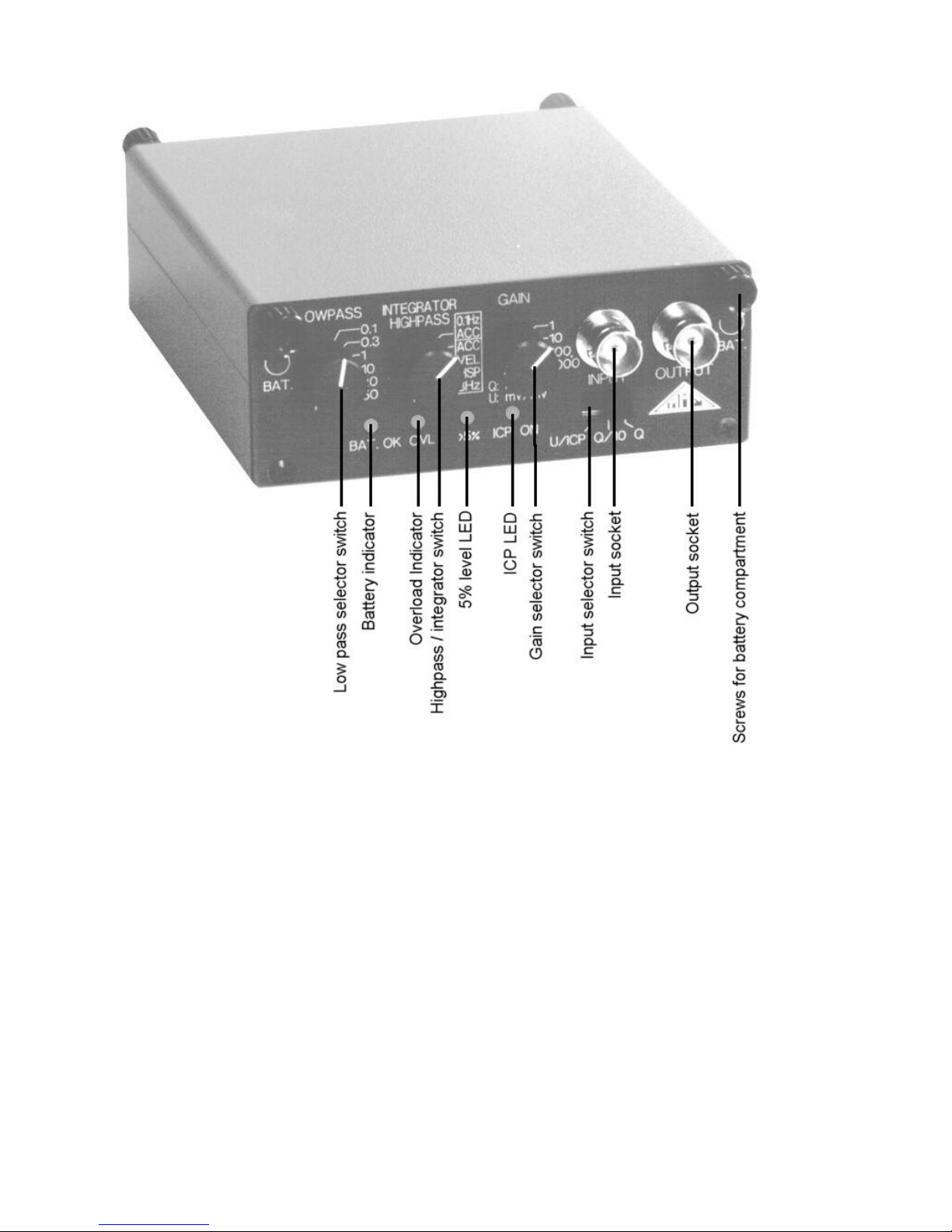
Figure 1: Front view of Model M68D1 with control elements
4
1. Application
The Signal Conditioners of M68 series are intended for connection of piezoelectric acceleration,
force or pressure transducers. The input is suitable for sensors with charge output as well as for
IEPE compatible transducers or microphones.
By means of the M68 the sensor signal can be best possibly adapted to the existing measuring
equipment or PC-based data acquisition systems. The Signal Conditioners provide the following
functions:
• Adaptation of the sensor signal and sensor supply
• Amplification
• High- and low-pass filtering (for example anti-aliasing filter)
• Integration of the sensor signal, for instance, to measure velocity or displacement.
Models M68D1 and M68D3 are housed in a rugged aluminum case. Both models can be used in
laboratory as well as under field conditions. Model M68D1 may also be operated from batteries.
Model M68R1 has been developed for multichannel measuring systems. It fits into 19”-rack
systems.
2. Function and Operation
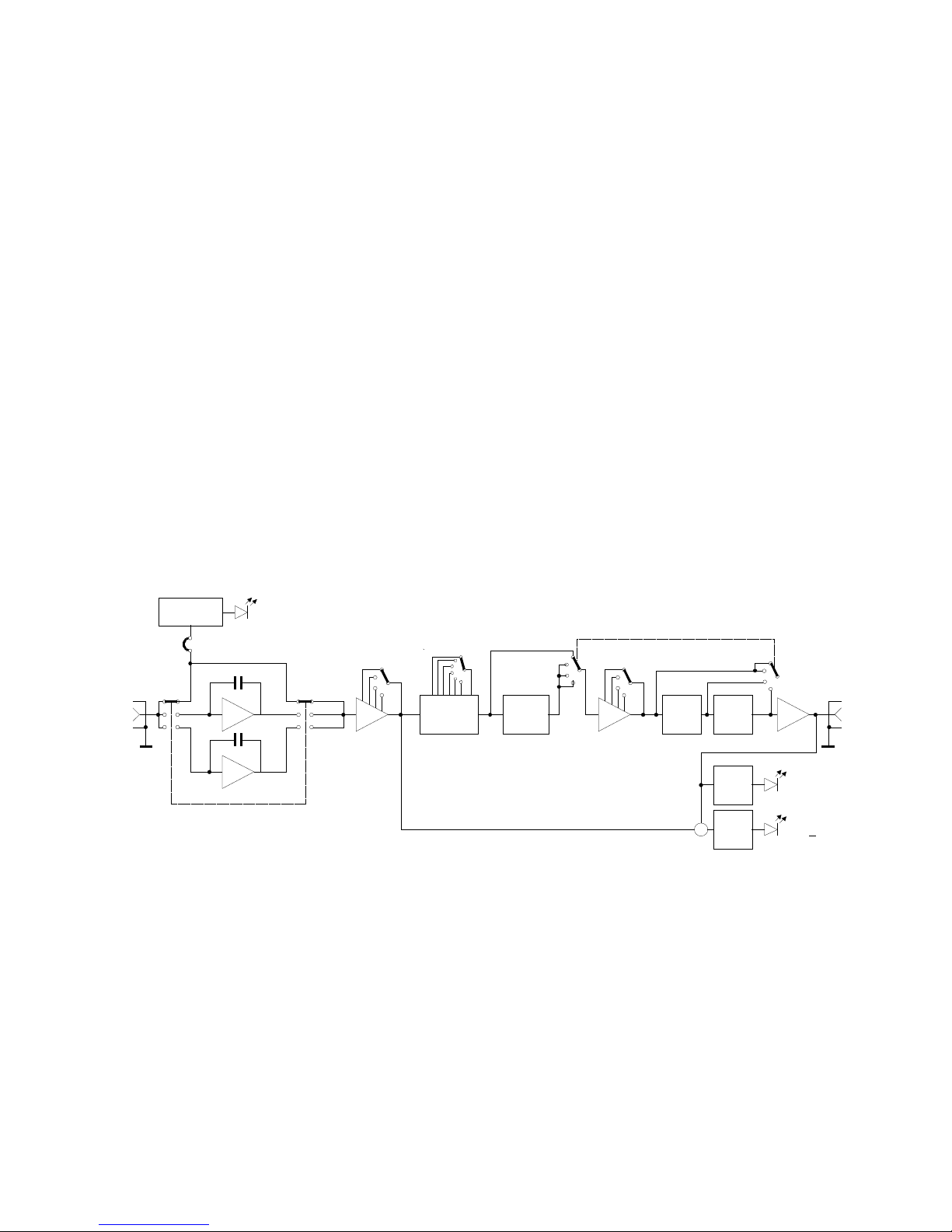
Figure 2 shows the block diagram of Model M68 with its most important functional groups.
Depending on the position of the input switch, the input signal passes the impedance converter
Q1 or Q2. If IEPE operation is selected, the signal is directly connected to the amplifier. At
IEPE operation a constant current is fed into the input socket to supply the sensor electronics.
The constant current source can be switched off by the internal jumper J1, in case an AC voltage
shall be connected to the input.
The input circuit is followed by the first amplifier stage, low pass and high pass filters. The low
pass filter has 6 selectable limiting frequencies. The high pass filter has a limiting frequency of 3
Hz, which can be bypassed by the switch “HIGH PASS / INTEGRATOR”. In this case the full
5
Figure 2: Block diagram
U
Q/10
Q
U
Q/10
Q
Q1
Q2
IEPE
supply
J1 (ICPon/off)
Low pass
Frequency
High
pass
0.1Hz
3Hz
V2 1. Int. 2. Int.V1
Gain
a
v
d
Gain
Input
Overload
Output
IEPE
+
Compa-
rator
>5%
V=1
Compa-
rator

bandwidth down to 0.1 Hz comes into effect. The filters are followed by the second amplifier
stage. The divided gain before and after filtering provides sufficient dynamic range, even for signal components outside the filter range. At the same time a high signal-to-noise ratio is achie ved.
Before reaching the output driver the signal may pass one or two integrating stages. The output
is DC coupled.
A control LED for the output modulation indicates an output signal higher than 5 % of full-scale
modulation. An overload LED shows if the output signal exceeds 90 % of full-scale modulation.
It also indicates overload before the filter stages.
Models M68D1, M68D3, and M68R1 have identical electronic circuits.
3. Power Supply
3.1. Grounding Concept
The inputs and outputs of the signal conditioners are single ended, i.e. asymmetrical. In case an
additional signal ground connection is required, ground is available via a separate connector at
the rear of the instruments. For the Models M68D1 and M68D3 this connector is a 4 mm banana jack. The signal ground of Model M68R1 can be found at the 4-pole frame connector.
The case of the instruments is internally connected to ground.
If model M68R1 is used with the rack cases M68B6 and M68B12 a connection is made between
signal ground and protective earth potential via the case.
The power supply is separated from signal ground. In some cases it may be of advantage to
connect the minus pole of the power supply to signal ground, to avoid ground loops. For this
purpose you can plug in the 4 mm jumper (delivered with the instruments) at the rear of Models
M68D1 and M68D3. At Model M68R1 the terminals of the power supply socket can be connec ted by a wire.
3.2. External Supply
The Signal Conditioners M68 are powered by an external DC voltage
Models M68D1 and M68D3 come with a mains plug adapter for 115/230 VAC. The power supply socket according to DIN 45323 is located at the rear of the instruments. Any other voltage of
5 V to 15 V DC and about 300 mA (for M68D1) or 1 A (for M68D3) may be connected to this
socket. The positive supply terminal is connected to center pin (tip). The POWER ON/OFF
switch is located at the rear.
The M68R1 also has its power supply connector at the rear. It is a 4-pole frame connector type
WAGO 232. The pin designation is shown in Figure 3.
Figure 3: Power supply socket of Model M68R1
6
+ 5 .. 15 V
0 V
Signal ground
0 V
 Loading...