

MMF KSI 80VC-20, KSI 80VC-40, KSI 82VB-20, KSI 82VB-40 User Manual
kManfred Weber
Metra Mess- und Frequenztechnik in Radebeul
D-01445 Radebeul Meissner Str. 58 Internet: www.MMF.de
Phone +49-351-836 2191 Fax +49-351-836 2940 Email: Info@MMF.de
Instruction Manual
Vibration Velocity Sensor / Transmitter KSI 80VC / KSI 82VB
1.Purpose
The vibration velocity transducers KSI 80VC / KSI 82VB are intended for continuous monitoring of
rotating machinery for trending or shutdown based on standard ISO 10816. The rugged, double shielded
and electrically insulated design allows applications under harsh environmental conditions. The sensors
provide a filtered and rectified output signal which is compatible with 4-20 mA current loop standard.
Hence it can be directly connected to standard equipment such as PLCs, panel meters or current relays.
Additional equipment for sensor supply and signal conditioning is not necessary.
The frequency ranges are 1.5 to 1000 Hz with model KSI 80VC and 10 to 1000 Hz with model
KSI 82VB.
Both types are available in two versions each with 20 mm/s nominal range (models KSI 80VC-20 /
KSI 82VB-20) and with 40 mm/s nominal range (models KSI 80VC-40 / KSI 82VB-40).
The sensors require no calibration.
2.Function
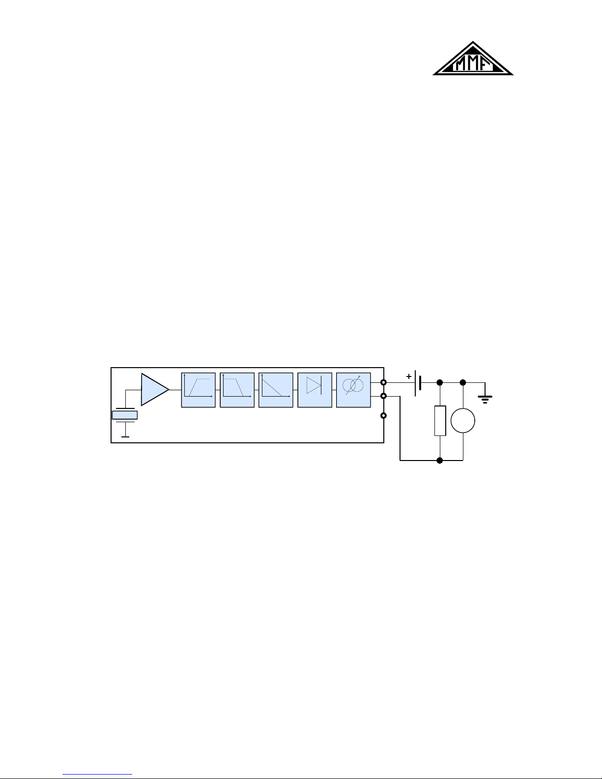
In spite of their small dimensions models KSI 80VC and KSI 82VB feature a complex signal conditioning
circuit. The main components are shown in Figure 1.
`
P ie z o
In t e g r a t.
T P 1 k H z R M S
4 - 2 0 m A
H P 1 ,5 /10 H z
RLU
S
V
K S I8 x V B
432
Figure 1: Block diagram and external connections
The sensing element is a precise piezoceramic ring-shear system. It measures vibration acceleration. The
acceleration signal is amplified followed by an integrator for vibration velocity. The signal is high pass
filtered at 1.5 Hz (KSI 80VC) or 10 Hz (KSI 82VB) and low pass filtered at 1000 Hz with 2 pole filters.
The frequency band of model KSI 82VB from 10 to 1000 Hz is usually sufficient for vibrations caused by
unbalance. It is also recommended in standard ISO 10816-1. In some applications with slow running
machinery it may be necessary to measure from 1.5 to 1000 Hz with model KSI 82VB.
A true RMS rectifier and a 4-20 mA current loop converter make the signal ready for long distance
transmission.
With the KSI 80VC / KSI 82VB no separate power supply is required. The sensor is loop powered.
3.Mounting and Connection
Mounting
An important condition for accurate vibration measurement is the selection of suitable measuring points on
the structure. For this purpose it can be helpful to consult a specialist with experience in machine
monitoring.
In general, it is advisable to measure vibration as near as possible to its source. This will minimize
distortion of the measured signal by transmitting mechanical components. Suitable measuring points are
rigid components, for instance the housing of bearings or gearboxes. Not recommended for vibration
measurement are lightweight, flexible and soft components.
The standard ISO 10816-1 gives some recommendations for suitable measuring points.
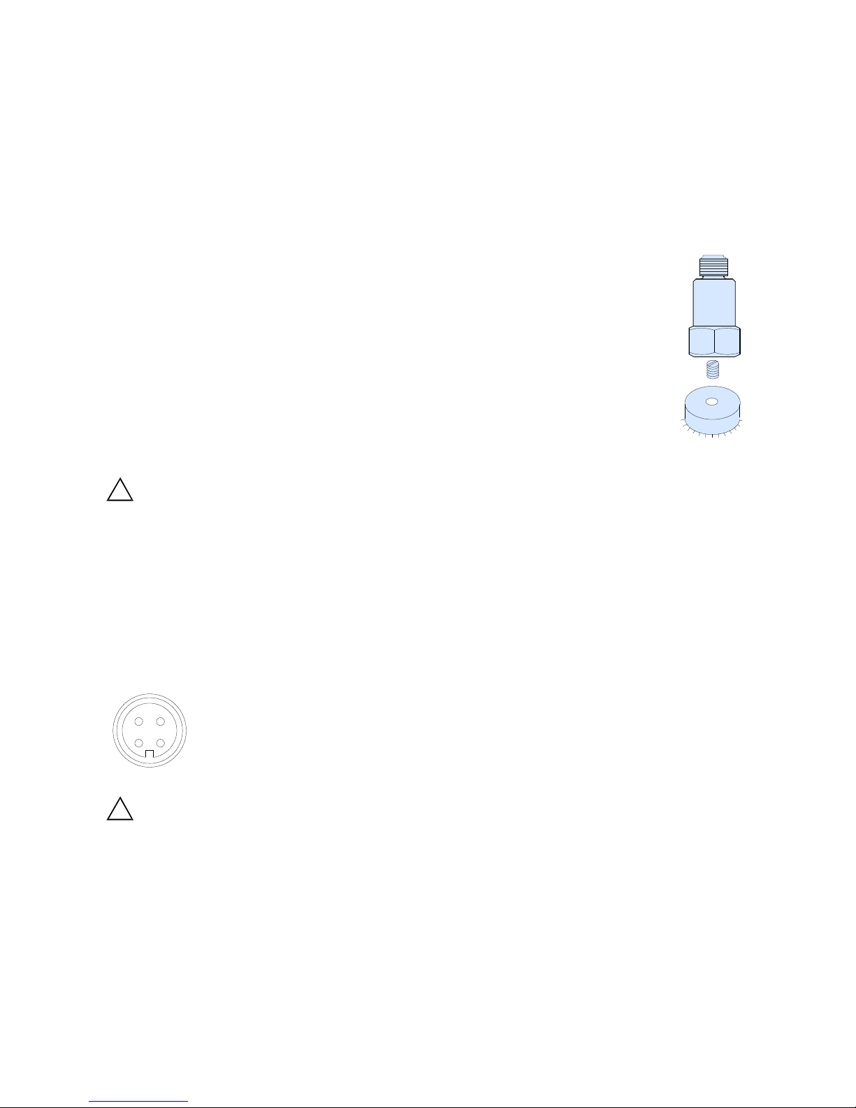
The KSI 80VC / KSI 82VB can be mounted using an M8 stud bolt which is screwed into the
tapped hole of the sensor base. The sensor can also be mounted by a magnetic base Model
208 (M8) or Model 008 (M5) with the adapter Model 044.
A perfect vibration transmission from the measuring object to the sensor is crucial for precise
results. Rough, scratched or too small measuring points may cause errors. Cast or varnish
surfaces are unsuited.
It is recommended to prepare the measuring point by epoxy cementing a polished steel plate
Model 229 with M8 stud. A thin layer of silicon grease will also improve vibration
transmission.
Connection
!
Please read the following carefully. Connection failures may cause malfunction or even
damage to the sensor.
Models KSI 80VC / KSI 82VB are connected via a waterproof four pin M12 connector model Binder 713.
The following optional connection accessories are available from Metra:
Model 080G/W: Straight (G) or angled (W) plug of Binder 713 series with screw terminals for simple
connection to existing cables, protection grade IP67
Model 084G/W: 5 m shielded cable with 4 wires, with straight (G) or angled (W) plug Binder 713 and
pigtail ends; protection grade IP67
The pin assignment is as follows:
View at socket Pin Assignment
1
2
3
4
1:
2:
3:
4:
No connection
+ current loop
- current loop
case
!
If the test object has no connection to earth potential, connect pin 4 to earth or another
reference potential to ensure proper shielding.
Make sure that the cable is not routed alongside AC power lines. It must cross AC power lines at right
angles. The cable should also be routed away from potential sources of EMI, e.g. motors, frequency
converters, generators, transformers or radio transmitters.
The sensor cable should be anchored to reduce stress at the connector. When securing the cable, leave
enough slack to allow free movement of the sensor.
The sensor output is connected via pin 2 and 3. Any two conductor cable can be used. At long distances
and high EMI, however, it is recommended to use shielded two conductor cables. The cable shield should
be tied to earth potential only at one side to avoid ground loops.
The 4-20 mA loop is powered from a filtered DC voltage source US as shown in Figure 1. The load resistor
RL is in series with the sensor. The load resistor RL and the voltage source US are often part of the read-out
or processing equipment. The KSI 80VC / KSI 82VB requires for normal operation a minimum voltage
KSI 80V
KSI 82V
M8
Epoxy
 Loading...