

MMD Equipment SDG25S-6A7, SDG45S-6A6, SDG125S-6A6, SDG65S-6A6, SDG150S-6A6 Service Manual
...
SERVICE MANUAL
MOBILE GENERATORS
SDG25S-6A7, SDG45S-6A6,
SDG65S-6A6, SDG100S-6A6,
SDG125S-6A6, SDG150S-6A6
MMD Equipment Inc.
121 High Hill Road
Swedesboro, NJ 08085
Tel: (800) 433-1382
Fax: (856) 467-5235
www.mmdequipment.com

Table of Contents
1. Specifications .........................................................................................................................................1-1
1.1 Specifications....................................................................................................................................1-1
1.2 Outline Drawing ................................................................................................................................
1.3 Internal Components.........................................................................................................................
2. Overhauling .............................................................................................................................................2-1
2.1 Cautions for Overhauling..................................................................................................................2-1
2.2 Tightening Torque.............................................................................................................................
2.3 Disassembly/Reassembly of Generator Main Unit
and Connection of Generator Main Unit and Engine.....................................................
2.4 Engine
Maintenance Standards........................................................................................................2-15
3. Electrical Parts ........................................................................................................................................3-1
3.1 Installation Positions of Electrical Appliances....................................................................................
3.2 Electrical Parts of Generator.............................................................................................................
3.3 E
lectrical
Parts of E
ngine
................................................................................................................
3.4 Generator Wiring Diagram................................................................................................................
3.5 Engine Wiring Diagram.....................................................................................................................
4.
Troubleshooting
........................................................................................................................................4-1
4.1 Repairing Procedures........................................................................................................................
4.2 Generator Troubleshooting...............................................................................................................
4.3 Emergency Switch Functions............................................................................................................
4.4 Engine Troubleshooting....................................................................................................................
4.5 How
t
o Check....................................................................................................................................
5. References ..............................................................................................................................................
5.1 Generator’s Winding Wires Resistance Value [At the Temperature of 68°F (20°C)]........................
5.2 Forced Excitation Method.................................................................................................................
1-7
1-10
2-3
2-5
3-1
.
3-6
3-13
.
3-51
.
3-56
4-1
.
4-3
.
4-6
.
4-7
4-9
5-1
5-1
.
5-1

1.1 Specifications
Model SDG25S-6A7
Exciting system
Armature connection
Phase number Three Single
Power factor % 80 100
Frequency Hz 60
Rated output kVA 25 14.4
Generator
Rated output kW 20 14.4
Voltage V 240 480 240/120
Current A 60 30 60
Model
Type
Number of cylinders 4
Total displacement cu. in. (L) 133 (2.179)
Rated output hp (kW)
Revolution per minute rpm (min-1)
Engine
Lubricating oil capacity gal. (L) 2.1 (8)
Coolant capacity
(including radiator)
Battery 80D26R-MF (12V)
Fuel tank capacity gal. (L) 17 (65)
Overall length in. (mm) 67 (1,690)
Overall width in. (mm) 28 (700)
Overall height in. (mm) 37 (950)
Net dry weight lbs (kg) 1,355 (615)
General Specifications
Operating weight lbs (kg) 1,500 (680)
1. Specifications
Star with Neutral ZigZag
4-cycle, water-cooled, swirl chamber type
gal. (L)
Brushless
ISUZU AA-4LE1
31.5 (23.5)
1,800 (1,800)
1.6 (6)
1-1

Exciting system
Armature connection
Phase number Three Single
Power factor % 80 100
Frequency Hz 60
Rated output kVA 45 26
Generator
Rated output kW 36 26
Voltage V 240 480 240/120
Current A 108 54 108
Model
Type
Number of cylinders 4
Total displacement cu. in. (L) 180 (2.953)
Rated output hp (kW)
Engine
Revolution per minute rpm (min-1)
Lubricating oil capacity gal. (L) 2.6 (10)
Coolant capacity
(including radiator)
Battery 80D26R-MF (12V)
Fuel tank capacity gal. (L) 26 (100)
Overall length in. (mm) 74 (1,870)
Overall width in. (mm) 34 (860)
Overall height in. (mm) 48 (1,220)
Net dry weight lbs (kg) 2,040 (925)
General Specifications
Operating weight lbs (kg) 2,260 (1,025)
1. Specifications
Model SDG45S-6A6
Brushless
Star with Neutral ZigZag
gal. (L)
4-cycle, water-cooled, direct injection type with turbo
NISSAN DIESEL 2A-BD30T
charged
58.3 (43.5)
1,800 (1,800)
2.9 (11)
1-2

Exciting system
Armature connection
Phase number Three Single
Power factor % 80 100
Frequency Hz 60
Rated output kVA 63 36.5
Generator
Rated output kW 50 36.5
Voltage V 240 480 240/120
Current A 152 76 152
Model
Type
Number of cylinders 4
Total displacement cu. in. (L) 264 (4.329)
Rated output hp (kW)
Engine
Revolution per minute rpm (min-1)
Lubricating oil capacity gal. (L) 3.7 (14)
Coolant capacity
(including radiator)
Battery
Fuel tank capacity gal. (L) 36 (135)
Overall length in. (mm) 82 (2,090)
Overall width in. (mm) 34 (860)
Overall height in. (mm) 48 (1,220)
Net dry weight lbs (kg) 2,600 (1,180)
General Specifications
Operating weight lbs (kg) 2,855 (1,295)
1. Specifications
Model SDG65S-6A6
Brushless
Star with Neutral ZigZag
gal. (L)
4-cycle, water-cooled, direct injection type with turbo
ISUZU EE-4BG1T
charged
77.7 (58)
1,800 (1,800)
4.0 (15)
80D26R-MF×2 (24V)
1-3

Exciting system
Armature connection
Phase number Three Single
Power factor % 80 100
Frequency Hz 60
Rated output kVA 100 58
Generator
Rated output kW 80 58
Voltage V 240 480 240/120
Current A 241 120 242
Model
Type
Number of cylinders 6
Total displacement cu. in. (L) 396 (6.494)
Rated output hp (kW)
Engine
Revolution per minute rpm (min-1)
Lubricating oil capacity gal. (L) 5.3 (20)
Coolant capacity
(including radiator)
Battery
Fuel tank capacity gal. (L) 59.4 (225)
Overall length in. (mm) 106 (2,700)
Overall width in. (mm) 46 (1,180)
Overall height in. (mm) 55 (1,400)
Net dry weight lbs (kg) 3,880 (1,760)
General Specifications
Operating weight lbs (kg) 4,390 (1,990)
1. Specifications
Model SDG100S-6A6
Brushless
Star with Neutral ZigZag
gal. (L)
4-cycle, water-cooled, direct injection, turbo charged,
ISUZU EE-6BG1T
intercooled
150.2 (112)
1,800 (1,800)
6.3 (24)
95D31R-MF×2 (24V)
1-4

Exciting system
Armature connection
Phase number Three Single
Power factor % 80 100
Frequency Hz 60
Rated output kVA 125 72
Generator
Rated output kW 100 72
Voltage V 240 480 240/120
Current A 300 150 300
Model
Type
Number of cylinders 6
Total displacement cu. in. (L) 436 (7.15)
Rated output hp (kW)
Engine
Revolution per minute rpm (min-1)
Lubricating oil capacity gal. (L) 5.3 (20)
Coolant capacity
(including radiator)
Battery 170F51 (12V)
Fuel tank capacity gal. (L) 66 (250)
Overall length in. (mm) 119 (3,030)
Overall width in. (mm) 46 (1,180)
Overall height in. (mm) 58 (1,480)
Net dry weight lbs (kg) 4,805 (2,180)
General Specifications
Operating weight lbs (kg) 5,335 (2,420)
1. Specifications
Model SDG125S-6A6
Brushless
Star with Neutral ZigZag
gal. (L)
4-cycle, water-cooled, direct injection, turbo charged,
VOLVO TAD720GE
intercooled
190.4 (142)
1,800 (1,800)
6.6 (25)
1-5

Exciting system
Armature connection
Phase number Three Single
Power factor % 80 100
Frequency Hz 60
Rated output kVA 150 87
Generator
Rated output kW 120 87
Voltage V 240 480 240/120
Current A 361 180 363
Model
Type
Number of cylinders 6
Total displacement cu. in. (L) 436 (7.15)
Rated output hp (kW)
Engine
Revolution per minute rpm (min-1)
Lubricating oil capacity gal. (L) 5.3 (20)
Coolant capacity
(including radiator)
Battery 170F51 (12V)
Fuel tank capacity gal. (L) 66 (250)
Overall length in. (mm) 119 (3,030)
Overall width in. (mm) 46 (1,180)
Overall height in. (mm) 58 (1,480)
Net dry weight lbs (kg) 5,137 (2,330)
General Specifications
Operating weight lbs (kg) 5,665 (2,570)
1. Specifications
Model SDG150S-6A6
Brushless
Star with Neutral ZigZag
gal. (L)
4-cycle, water-cooled, direct injection, turbo charged,
VOLVO TAD720GE
intercooled
190.4 (142)
1,800 (1,800)
6.6 (25)
1-6
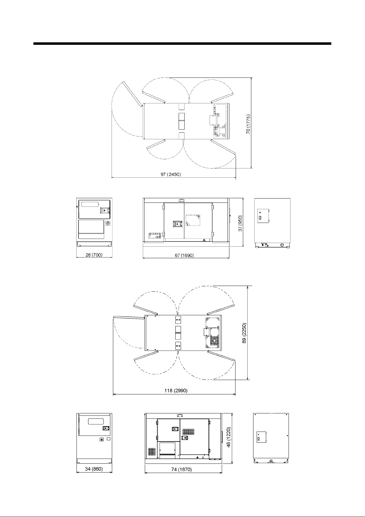
1.2 Outline Drawing
SDG25S-6A7 Unit : in. (mm)
1. Specifications
SG06052
SDG45S-6A6
SG06053
1-7
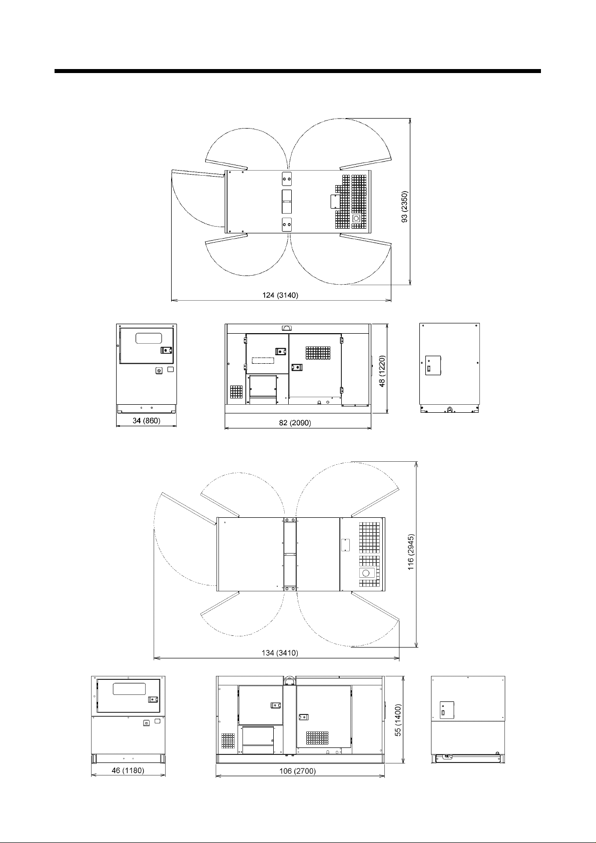
1. Specifications
SDG65S-6A6 Unit : in. (mm)
SG06054
SDG100S-6A6
SG06055
1-8

1. Specifications
SDG125S-6A6 Unit : in. (mm)
SG06056
SDG150S-6A6
SG06057
1-9
1. Specifications
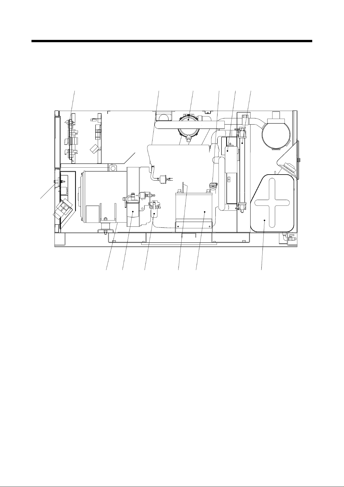
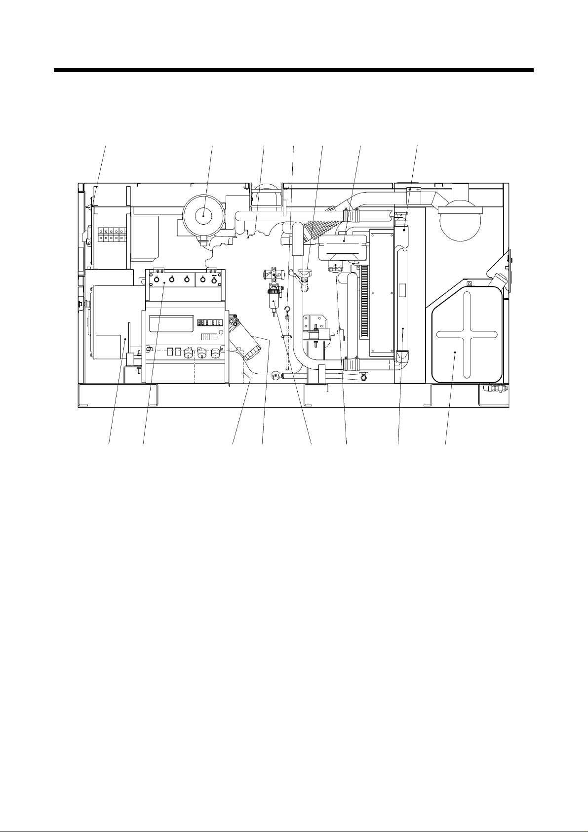
1.3 Internal Components
SDG25S-6A7
13
1. Control panel
2. Engine
3. Air filter
4. Engine oil filler port
5. Reserve tank
6. Radiator
7. Fuel tank
12 11 10 9 8 7
A040574
8. Battery
9. Engine oil level gauge
10. Sedimenter
11. Fuel filter
12. Generator main unit
13. Output terminals
1-10

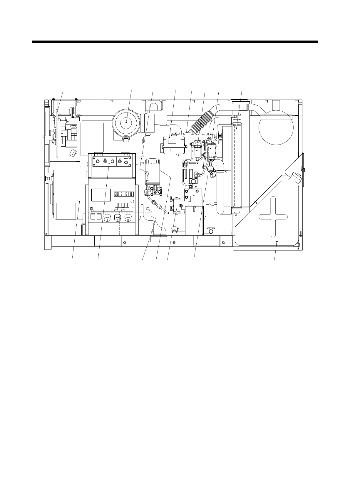
1. Specifications
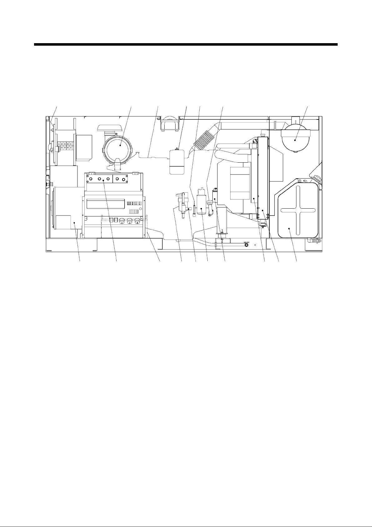
SDG45S-6A6
1 2 3 4 5 6
15
1. Control panel
2. Engine
3. Air filter
4. Reserve tank
5. Engine oil filler port
6. Radiator
7. Fuel tank
8. Sedimenter
14 13 12 11 10 9 8 7
9. Filter for electromagnetic pump
10. Fuel air-bleeding electromagnetic pump
11. Battery
12. Fuel filter
13. Engine oil level gauge
14. Output terminals
15. Generator main unit
A040575
1-11
1. Specifications
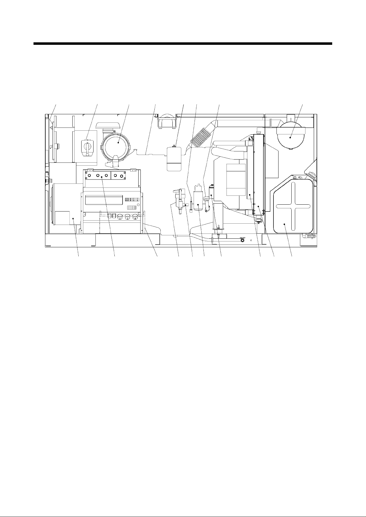
SDG65S-6A6
1 2 3 4 5 6 7 8
15 14 13 12 11 10 9
1. Control panel
2. Air filter
3. Engine oil level gauge
4. Reserve tank
5. Engine
6. Sedimenter
7. Fuel filter
8. Radiator
9. Fuel tank
10. Engine oil filler port
11. Fuel air-bleeding electromagnetic pum p
12. Engine oil filter
13. Battery ※
14. Output terminals
15. Generator main unit
Instrument 13 marked “※” are provided
on the other side (opposite side of
maintenance).
A040576
1-12
1. Specifications
A
SDG100S-6A6
1 2 3 4 5 6 7
15 14 13 12 11
10 9 8
050016
1. Control panel
2. Air filter
3. Engine
4. Engine oil level gauge ※
5. Engine oil filler port ※
6. Reserve tank
7. Radiator ※
8. Fuel tank
9. Intercooler
10. Fuel filter
11. Sedimenter
12. Engine oil filter
13. Battery ※
14. Output terminals
15. Generator main unit
Instrument 4,5,7,13 marked “※” are
provided on the other side (opposite side
of maintenance).
1-13
1. Specifications
A
SDG125S-6A6
1
2 3 4 5 6 7
17 16
15 14 13
12 11 10 9 8
1. Control panel
2. Air filter
3. Engine
4. Reserve tank
5. Engine oil level gauge
6. Engine oil filler port
7. Exhaust muffler
8. Fuel tank
9. Radiator
10. Intercooler
11. Fuel filter
12. Engine oil filter
13. Fuel pump
14. Fuel pre- filter
15. Battery ※
16. Output terminals
17. Generator main unit
Instrument 15 marked “※” are provided
on the other side (opposite side of
maintenance).
050157-1
1-14
1. Specifications
A
SDG150S-6A6
1 18
2
3 4 5 6 7
17 16
15 14 13
12 11 10 9 8
050585
1. Control panel
2. Air filter
3. Engine
4. Reserve tank
5. Engine oil level gauge
6. Engine oil filler port
7. Exhaust muffler
8. Fuel tank
9. Radiator
10. Intercooler
11. Fuel filter
12. Engine oil filter
13. Fuel pump
14. Fuel pre- filter
15. Battery ※
16. Output terminals
17. Generator main unit
18. Voltage selector switch
Instrument 15 marked “※” are provided
on the other side (opposite side of
maintenance).
1-15

2. Overhauling
2.1 Cautions for Overhauling
2.1.1 Precautions before starting work
(1) Work to be performed
It is very important to always plan in advance what facilities, tools, instruments, materials, oil,
etc. you will need to use; the exact locations and methods of performing inspection, adjustment,
or disassembly; and the key points of any repair wo rk to be performed.
(2) Care not to spill oil
Use a pan to collect used engine oil when changing the oil or attaching or detaching an oil line.
If a large volume of oil is expected to flow out make sure to drain any accumulated oil from the
engine oil pan in advance.
(3) Care when detaching parts
When disassembling a complicated part, put a matching mark to indicate the position of
detached parts for future reference. Make sure that the negative cable is detached from the
battery terminals before starting repair work.
(4) Tools to be prepared
1. Measuring instruments (e. g. tester, insulation resistance gauge etc.)
2. Tools
3. Torque wrenches
4. Jigs and specialized tools
5. Solder and soldering iron
6. Sealing tape
7. Molybdenum sulfide (tube type)
8. Lithium-base grease
9. Diesel oil (cleaning solvent)
10. Cleaning cloths
11. Literatures (such as manuals etc.)
2-1

2. Overhauling
2.1.2 Disassembly and assembly
(1) Wash dirt, dust and grime off vinyl tube and fuel hose before removing it, and take necessary
steps to cover or tape the openings of vinyl tubes or fuel hoses to prevent any dirt from entering
them.
(2) Perform disassembly work in a dust-free location whenever possible.
(3) When disassembling parts, wash their outer surface and place them on a clean sheet of paper or
cloth, taking care not to contaminate or damage them.
(4) Wash disassembled parts with diesel oil (cleaning solvent) after checking for contamination or
discoloration. However, do not wash rubber parts with diesel oil.
(5) Be careful not to damage disassembled parts, they are precision built.
(6) Replace consumables such as oil seals, O-rings, filters, oil, etc. with new items when
reassembling parts.
(7) Apply a coating of clean grease to O-rings when installing them in the machine.
(8) When reassembling parts, place each part in the order of assembly and take care that no parts
are missing or misassembled.
(9) When reassembling an assembled part (set part), be sure to replace it as an assembly.
(10)Contamination or rusting may occur due to dust or humidity if parts are left in disassembled or
partly disassembled condition for a long time. Therefore, be careful to prevent dust or rust from
affecting parts if you have to leave the repair incomplete f or a long period of time.
(11)Check tightening torque and cl earance when assembling parts.
(12)Check the direction of rotation, speed, and oil leakage after assembly.
(13)Before starting the machine after disassembly, run it at low idle to check for unusual noises, etc.
to prevent engine or generator damage.
2-2
2. Overhauling
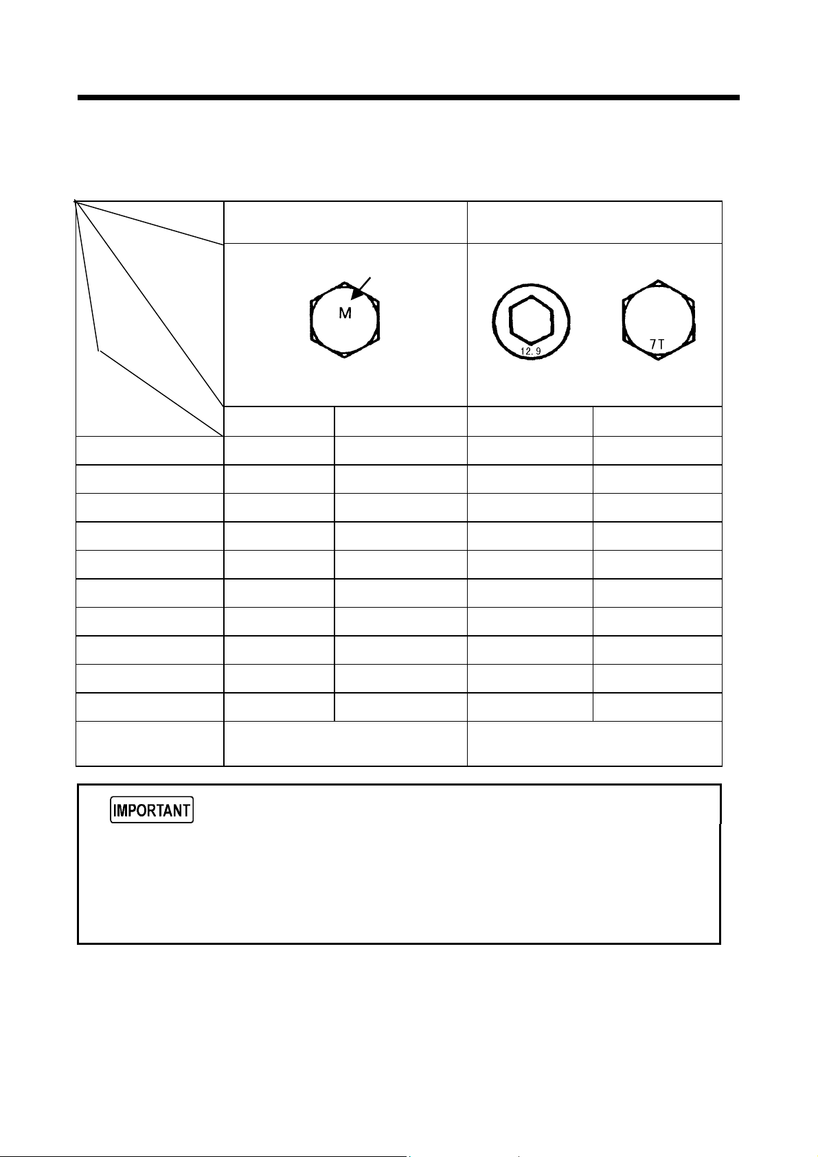
2.2 Tightening Torque
2.2.1 General tightening torque of bolts and nuts
Fasten all the bolts and nuts with the specified tightening torque when assembling.
Torque
Nominal diameter
(mm)
Type
Strength,
classification,
and indication
example
6 3.7 5 (51) 7.2 10 (100)
8 9.0 12 (124) 18 25 (245)
10 18 25 (245) 35 49 (485)
12 31 43 (425) 61 85 (845)
14 49 68 (675) 98 135 (1350)
16 76 106 (1055) 152 210 (2100)
Low or medium carbon steel bolt
(SS400B, etc.)
4.6−6.8 (4T−6T)
Indication does
not appear in
some cases.
Hexagon headed bolt
•
m (kgf•cm)
lbw・ft
N
High strength steel bolt
(SCM435, etc.)
8.8−12.9 (7T−12T)
Socket bolt
lbw・ft
Hexagon headed bolt
N•m (kgf•cm)
18 105 145 (1450) 210 290 (2900)
20 148 205 (2050) 297 410(4100)
22 203 280 (2800) 405 560 (5600)
24 250 345 (3450) 514 710 (7100)
Applied sections.
For general sections such as bonnet
and frame.
For specified sections.
Each clamping torque listed in the above-mentioned table applies to bolts being used
for generators.
The list shows normal clamping torque. In some sections, special specified torque is
required. In such a case, use the specified torque only.
Make sure to remove rust and dust before tightening.
2-3
2. Overhauling
2.2.2 Tightening torque for terminal plate
When connecting the output terminals of the generator, it is important to tighten the
screws, according to the designated torque.
Since the terminal is so small, it could be burned or damaged without the proper
torque.
Bolt size
M3.5 0.7 [1.0 (10)]
M4 1.1 [1.5 (15)]
M5 2.2 [ 3 (30)]
M6 3.7 [ 5 (51)]
M8 7.2 [10(100)]
M10 12.7 [18(175)]
M12 25 [35(350)]
Tightening torque
lbw・ft [N
•m (kgf•cm)]
2-4
2. Overhauling
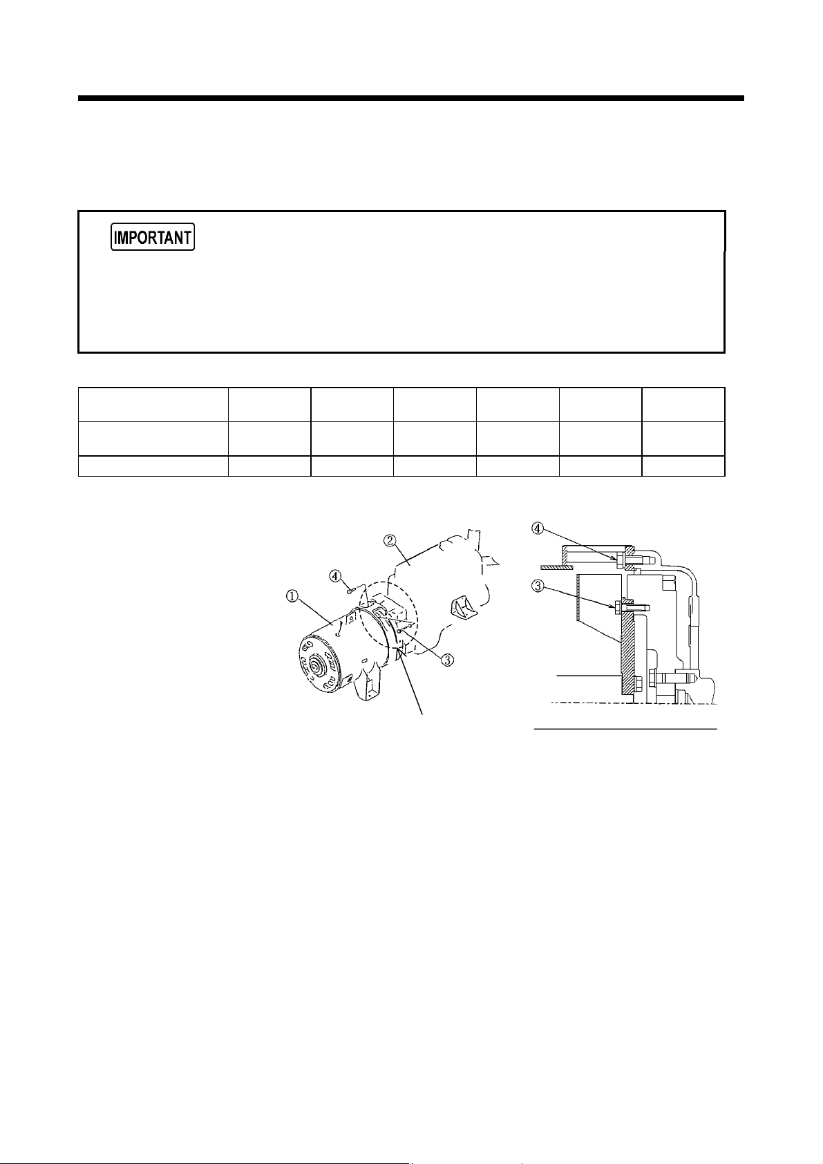
2.3 Disassembly/Reassembly of Generator Main Unit and Connection
of Generator Main Unit and Engine
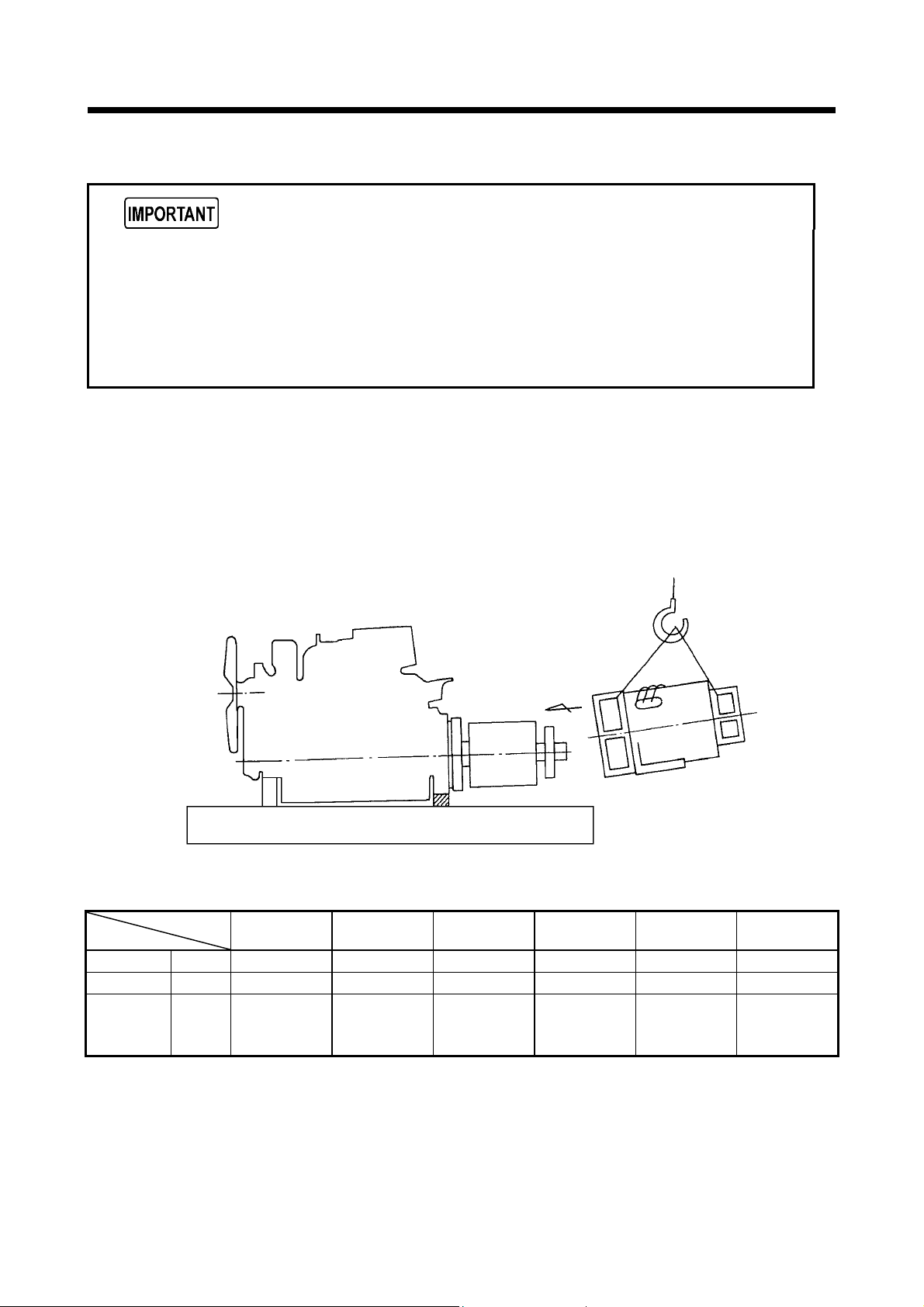
2.3.1 Disassembly of generator main unit
The generator main unit is unilaterally mounted and the clearance is small, so it must
be handled with extreme care to avoid the possibility of damage to the rotor or stator.
Use hoisting equipment of sufficient capacity when it is necessary to lift up the engine
and the generator main unit.
Lifting weight
Weight of generator
main unit
Weight of engine
Unit : lbs (kg)
SDG25S
-6A7
320 (145) 452 (205) 595 (270) 794 (360) 980 (445) 1,224 (555)
392 (178) 550 (250) 810 (368) 1,036 (470) 1,500 (680) 1,500 (680)
SDG45S
-6A6
SDG65S
-6A6
SDG100S
-6A6
SDG125S
-6A6
①
Generator main unit
②
Engine
③
Bolts (for coupling of
the engine flywheel
and the generator
coupling)
④
Bolts (for connection of
the engine flywheel
housing and the
generator main unit
frame)
AA section (coupling) details
SDG150S
-6A6
SG05046
2-5
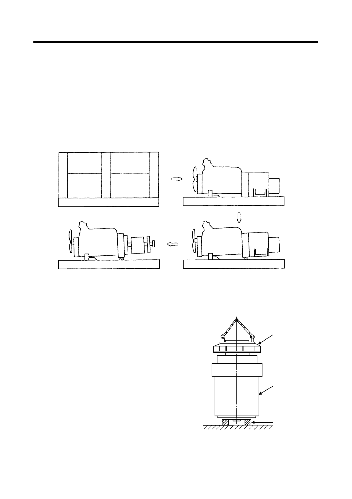
(1) Procedures of disassembly
1. Remove cables from battery (-) termin al.
2. Remove brackets (or fittings for muffler, air filter and etc.) equipped on the bonnet.
3. Remove top cover and dismantle such parts on the bonnet so that generator main unit can be
pulled out.
4. Remove cables and pipes.
5. Remove mounting bolts of generator main unit and engine.
6. Remove engine cooling fan guard and fan shroud.
7. If necessary, remove radiator, radiator hoses, fuel tank and battery.
8. Insert a angle timber under the engine housing for inclining the engine.
9. Separate engine housing and generator stator.
10. Separate engine flywheel and gen erator rotor.
2. Overhauling
※If insulation film is damaged by contact of stator and rotor during disassembly of generator
main unit, perform varnish drying treatment to such portion.
(2) Demounting stator and rotor at the same time from engine
When demounting stator and rotor of generator
main unit at the same time from engine, place the
generator main unit with the engine coupling face
upward, and pull out the rotor.
At this time, stabilize the generator main unit
frame padded by wooden block at the bearing side
face.
(The generator main unit separated from engine
should be kept firm with the rotor in the stator
fastened by wire or rope to prevent them from
moving. Then start this job.)
Generator coupling
Generator main unit
frame
Wooden block
SG06058
2-6

2. Overhauling
A
2.3.2 Measuring center deviation and surface deviation
Measure them with a dial gauge pressed to the flywheel.
(1) Measuring the center deviation, turn the rotor with the dial gauge pressed to the circumference
of the coupling flange. If the biggest value measured on the same circumference exceeds 0.008in.
(0.2mm), it is necessary to repair it.
(2) Measuring the side run-out, turn the rotor with the dial gauge pressed vertically to the coupling
flange. If the biggest value measured on the same diameter exceeds 0.008in.(0.2mm), it is
necessary to repair it.
: Flywheel side run-out
B : Housing center deviation
SG06059
2-7
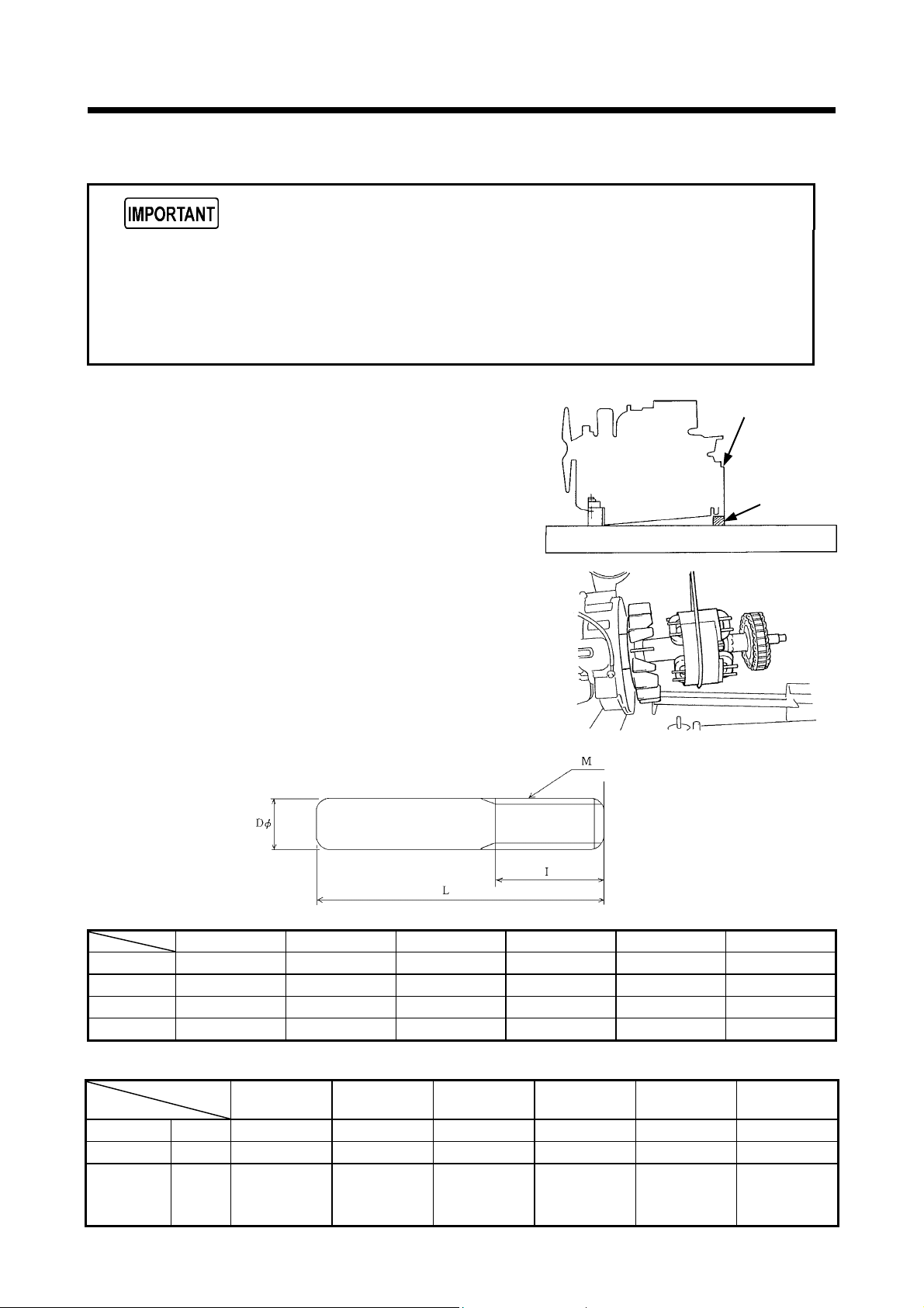
2. Overhauling
2.3.3 Assembly of engine flywheel and generator coupling (rotor)
The mounting holes are not equally spaced along the circumference. Therefore,
position the holes in advance so as to match the coupling counterpart by turning and
adjusting the engine flywheel.
Use guide bolts while centering to mount the assembly.
Tighten the bolts to the specified torque.
(1) Mounting engine
Mount the engine on the vibration isolator rubber
at the frame side of engine. Put angle wooden block
under the engine housing and incline the engine a
little.
(2) Install rotor
1. Hang the center of the rotor with jute rope and
bring it near to the flywheel.
2. Match the rotor coupling plate to the engine
flywheel and then combine them, tightening the
coupling connecting bolts.
The coupling connecting bolts shall be high
tensile bolts 7T or more. (Use 2 guide bolts for
this job.)
Size of guide bolt
Engine
Flywheel housing
Wooden
block
SG05047
(mm)
Dφ 7.5 9.5 ← ← ← ←
L 60 75 ← 65 75 ←
I 25 ← ← ← ← ←
M M8×1.25 M10×1.5 ← ← ← ←
Tightening torque of generator coupling (rotor) (See ③ of 2.3.1 bolts)
Bolt size M8×1.25-30 M10×1.5-40 M10×1.5-30 M10×1.5-50 M10×1.5-20 ←
Quantity 8 ← ← 9 8
Tightening
torque
SDG25S-6A7 SDG45S-6A6 SDG65S-6A6 SDG100S-6A6
lbw・ft
[N
・
m]
(kgf・cm)
SDG25S
-6A7
23.5
[33]
(325)
SDG45S
-6A6
46
[62.8]
(640)
SDG65S
-6A6
← ← ← ←
2-8
SDG100S
-6A6
SDG125S-6A6 SDG150S-6A6
SDG125S
-6A6
SDG150S
-6A6
←
2. Overhauling
2.3.4 Assembly of flywheel housing and generator main unit frame (stator)
Handle the stator with care after fastening the engine flywheel and generator
coupling, to avoid damage to either the rotor or stator.
Tighten the connections to the specified torque.
For connection of flywheel housing and generator main unit frame (stator), coat
anti-corrosion agent “ METAL CLEAR” on the connecting faces to prevent rust and
corrosion.
Install the stator
1. Carefully push into the stator, preventing the stator and rotor from rubbing each other.
2. Install the flywheel housing and the stator, tightening the connecting bolts.
The bolts should be high tensile 7T or more.
3. Remove the angle wooden block from under the flywheel housing, and place the generator
main unit and engine horizontally.
Tightening torque of generator main unit frame (stator) conne cting bolts. (See ④ of 2.3.1 Bolts)
Bolt size M10×1.5-25 M10×1.5-30 ← ← M10×1.5-30 ←
Quantity 12 ← ← ← ← ←
Tightening
torque
lbw・ft
[N
・
m]
(kgf・cm)
SDG25S
-6A7
18
[24]
(245)
SDG45S
-6A6
← ← ← ← ←
SDG65S
-6A6
SDG100S
-6A6
SDG125S
SG06060
-6A6
SDG150S
-6A6
2-9
2. Overhauling
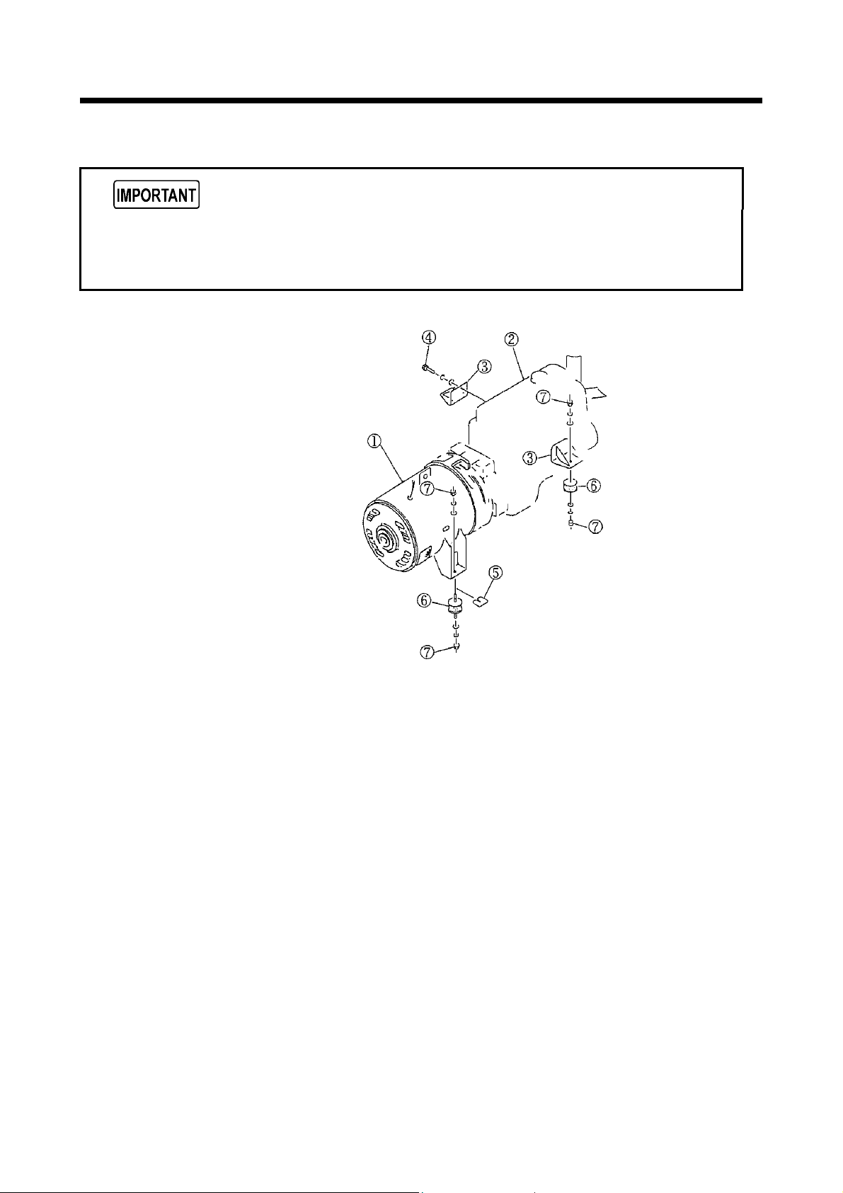
2.3.5 Mounting of generator main unit and engine on frame
Perform centering carefully, to avoid deviation in the horizontal leveling caused by
distortion of the frame or inaccurate mounting of the generator main unit and engine.
Running the machine without accurate centering may cause abnormal vibrations.
①
Generator main unit
②
Engine
③
Bracket
④
Bolt
⑤
Shim
⑥
Cushion rubber
⑦
Nut
SG05048
2-10
2. Overhauling
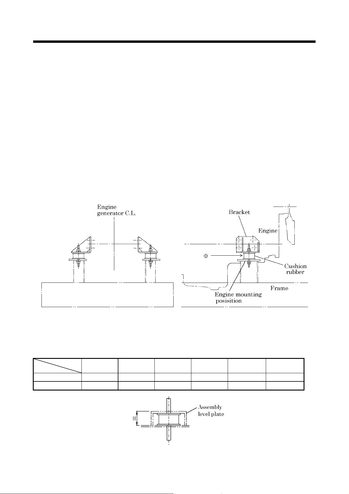
(1) Centering method
1. Mount the brackets on the engine secured to the generator main unit.
(Use only genuine fastening bolts.)
2. Place four assembly level plates ※ on the points for mounting the engine and the generator
main unit onto the frame.
3. Place the generator main unit with the engine mounted onto it on the assembly level plates
on the frame.
4. Use shims for adjustment if joint gaps are found at any of the four places where the brackets
and assembly level plates are to be fixed.
5. Lift the engine mounted onto the generator main unit, leaving the shims in the four places
after adjustment.
6. Remove the assembly level plates and place the cushion rubbers in their respective places on
the frame.
(Insert or place adjusting shims on the vibration isolator rubber of both engine and generator
main unit.)
7. Place the engine with the generator main unit on the cushion rubbers and fasten it with nuts.
(Placing vibration isolator rubber for SDG25S,65S, make sure to put plain washers on the
rubber. If not, the vibration isolator rubber is left loose. So vibration could damage vibration
isolator rubber and machine.)
8. Make sure to coat the bolts with anti-corrosion agent “ Metal Clear” which are tightened for
vibration isolators. ( 8 points consisting of upper side 4 p ieces and under side 4 pieces.)
SG05049E
※
Before installing vibratio n isolators, place assembl y level plate on the posit ion of generator main unit and
engine connection and then adjust the clearance between engine mounting bracket and assembly level
plate.
Assembling level plates size Unit : in. (mm)
SDG25S
-6A7
SDG45S
-6A6
SDG65S
-6A6
SDG100S
-6A6
SDG125S
-6A6
SDG150S
-6A6
Generator side 1.24 (31.5) 2.21 (56) 2.24 (57) 2.56 (65) 1.9 (48) ←
Engine side 0.98 (25) 2.21 (56) 2.24 (57) 2.56 (65) 1.85 (47) ←
2-11
SG05100E
2. Overhauling
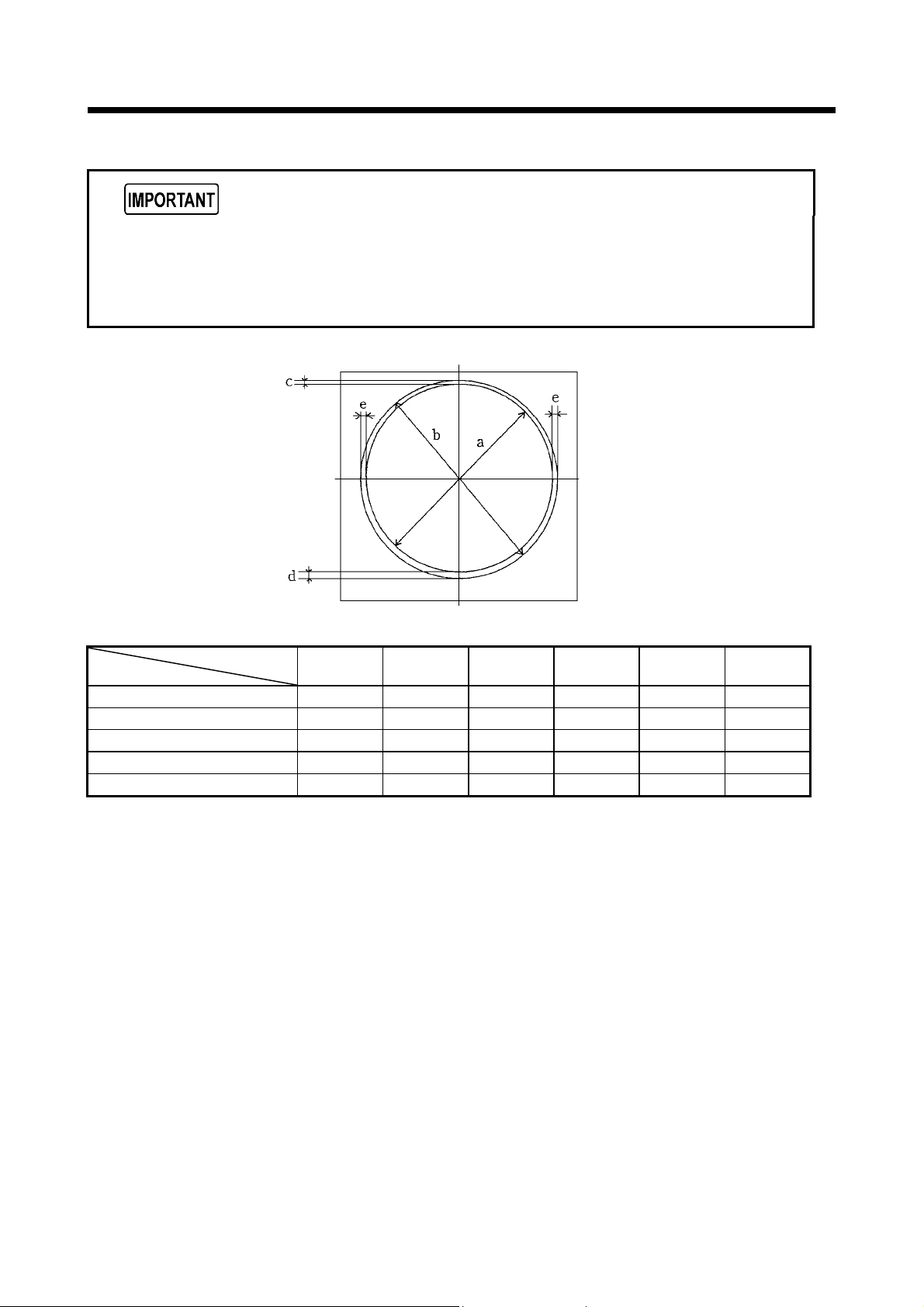
(2) Check the gap between the cooling fan and fan shroud
Maintain an adequate gap in both the vertical and horizontal directions.
If the fan is mounted incorrectly so that it leans toward one side wall of the shroud,
leading to a smaller gap in one direction, the fan may produce abnormal noise due to
rubbing against the shroud during starting or stopping and may also overheat.
SG05050
Gap size Unit : in. (mm)
Fan outer diameter
Shroud inner diameter
Top gap
Bottom gap
Side gap
SDG25S
-6A7
(a)
16.9 (430) ← 19.7 (500) 22.8 (580) 21.5 (546) ←
(b) 17.7 (450) ← 20.5 (520) 24.0 (610) 22.3 (566) ←
(c) 0.4 (10) 0.28 (7) ← 0.47 (12) 0.28 (7) ←
(d) 0.5 (13) ← ← 0.7 (18) 0.5 (13) ←
(e) 0.4 (10) ← ← 0.6 (15) 0.4 (10) ←
SDG45S
-6A6
SDG65S
-6A6
SDG100S
-6A6
SDG125S
-6A6
SDG150S
-6A6
2-12
2. Overhauling
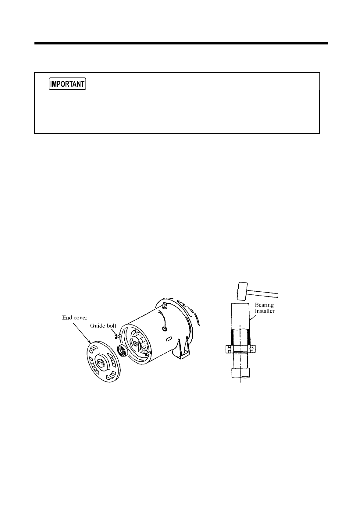
2.3.6 Changing the bearings in the generator main unit
Use guide bolts to avoid the danger of dropping the bearing shield and to prevent the
rotor and stator from rubbing against each other. (Use the guide bolts used to mount
the generator main unit.)
Do not hit the bearing outer race when installing or the bearing may be damaged.
The generator main unit is quipped with fully sealed bearing. It is not necessary to supply
grease. But the machine life (4 years or 15,000 ~ 20,000 hours of operation) may change,
depending upon the conditions such as vibration, ambient temperature and humidity. So always
make sure to check for any abnormal noise of the bearings and also to check for any abnormal
rise of temperature. Should it become necessary to replace the bearings, follow the under
mentioned procedures.
Replacement of bearings
1. Remove bearing shield (end cover).
2. Pull out the bearing from the shaft, using bearing removing tools (gear puller).
3. Clean the surface of the shaft and check for any damages.
4. Prepare a new bearing, and check it by turning it by hand before installing it.
5. Heat the bearing in the oil bath at average 100 to 118℃ (Never heat it over 120℃ or
partially.) and then install the bearing using a bearing installer (Heated bearing can be
installed to the shaft.)
6. Set guide bolts to the generator main unit frame.
7. Push in the bearing shield (end cover), hitting it with a plastic hammer evenly.
SG06061 SG06062
2-13
 Loading...