

MMD Equipment MMD 70, AC70 Maintance Manual

OPERATOR’S, MAINTENANCE
AND PARTS MANUAL
AIR COMPRESSOR
MMD 70
MMD Equipment Inc.
121 High Hill Road
Swedesboro, NJ 08085
Tel: (800) 433-1382
Fax: (856) 467-5235
www.mmdequipment.com

TABLE OF CONTENTS
Operation & Maintenance Section
Page
Specifications ... 2
Safety ... 3-15
Description of Components ... 16-21
Compressor Operation ... 22-26
Compressor Inspection, Lubrication,
And Maintenance ... 27-37
Troubleshooting ... 38-41
Recommended Spare Parts List ... 42
Warranty Section
Warranty Information/Claims ... 43-48
Parts & Illustration Section
49-57
1
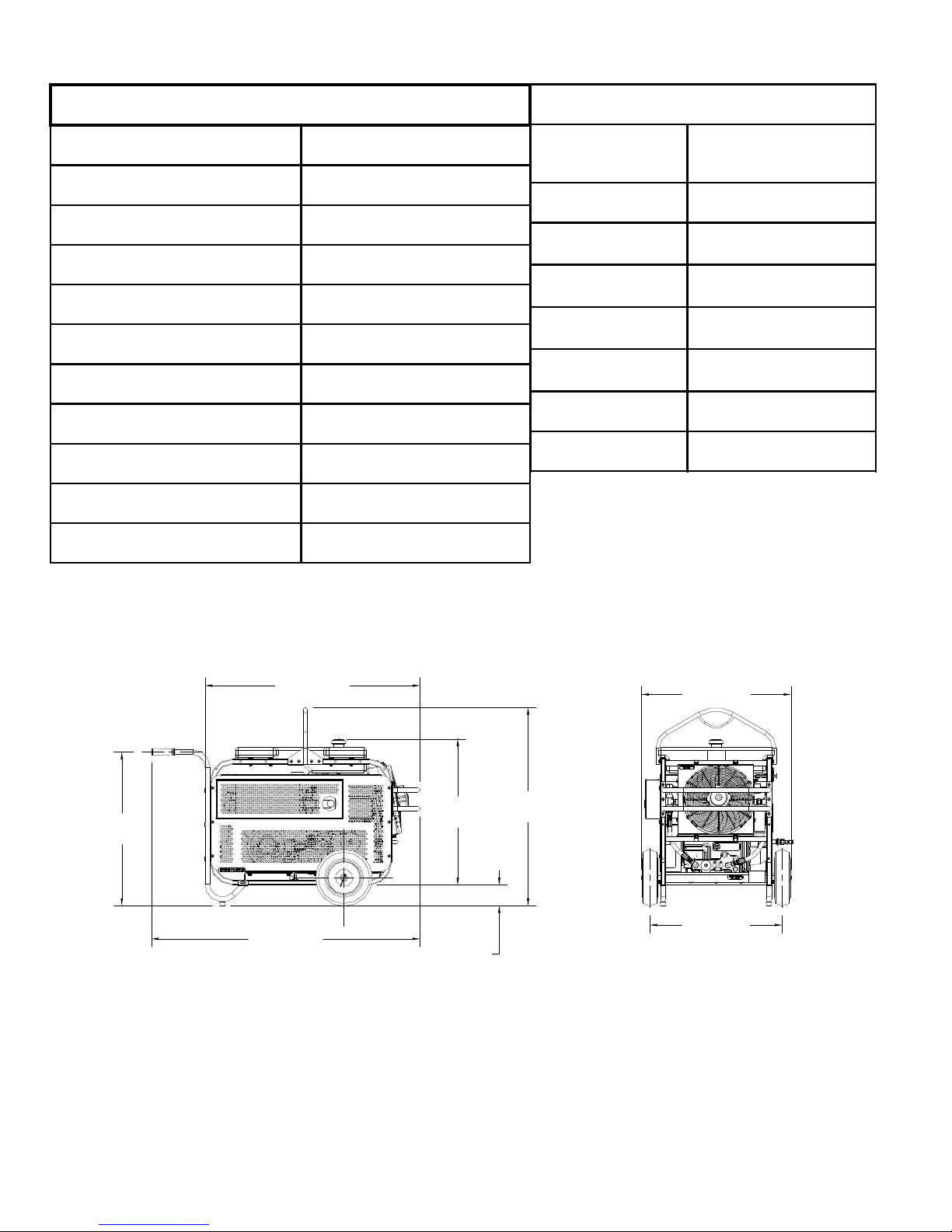
COMPRESSOR SPECIFICATIONS
ENGINE SPECIFICATIONS
MODEL AC70
TYPE OIL FLOODED ROTARY SCREW
DELIVERY (CFM) 70 CFM @ 100 PSIG (1.98m3/min)
OPERATING PRESSURE RANGE 80-115 PSIG
AMBIENT OPERATING TEMP. RANGE -20 DEG TO +105 DEG F
OIL SUMP CAPACITY .75 GALLONS (2.83 LITERS)
TOTAL SYSTEM CAPACITY 1.0 GALLON (3.80 LITERS)
AIR SERVICE CONNECTION 1/2" NPT
TYPE COOLING SYSTEM OIL TO AIR
AIR INTAKE FILTER SINGLE STAGE DRY
TYPE OF CONTROL 0 - 100% DEMAND
HONDA 4-CYCLE, V-TWIN
TYPE
OHV AIR COOLED
GASOLINE
MODEL GX620K1-BOSS
POWER @3600RPM HP (kw)
DISPLACEMENT - cu. in.
(cc)
BORE & STROKE
OIL CAPACITY w/
FILTER
20 HP (15kw)
37.5 cu. in. (614cc)
B - 3.03in (77mm) & S - 2.60in
(66mm)
1.5 QUARTS (1.4 LITERS)
BATTERY 12V - 275cca @ 0 DEG F
FUEL TANK CAPACITY 8 GALLONS (30.28 LITERS)
WEIGHT 430lbs (195kg)
30 1/2
[774.2 mm]
42 5/8
[1082.8 mm]
53 1/4
[1353.0 mm]
28 7/8
[734.7 mm]
4 1/8
[104.2 mm]
29 5/8
[752.5 mm]
39 1/4
[997.1 mm]
26 1/4
[667.0 mm]
2

SAFETY
WARNING
ALL UNITS ARE SHIPPED WITH A DETAILED OPERATOR’S, INSTALLATION AND
PARTS MANUAL. THIS MANUAL CONTAINS VITAL INFORMATION FOR SAFE AND
EFFICIENT OPERATION OF THIS UNIT. CAREFULLY READ THE OPERATORS
MANUAL BEFORE STARTING THE UNIT. FAILURE TO READ AND COMPREHEND THE
INSTRUCTIONS COULD RESULT IN SERIOUS BODILY INJURY OR PROPERTY DAM-
AGE.
GENERAL
The compressor is designed and manufactured to operate with relative safety. However,
the responsibility for safe operation rests with those who use and maintain these products. The following safety precautions are offered as a guide, which, if conscientiously
followed, will minimize the possibility of accidents throughout the useful life of this
equipment.
Only those who have read and understand this operator’s manual should operate this air
compressor. Failure to follow the instructions, procedures and safety precautions in this
manual may increase the possibility of accidents and injuries.
Never start this air compressor unless it is safe to do so. Do not attempt to operate the
air compressor with a known unsafe condition. Tag the air compressor and render it
inoperative by disconnecting the battery so others who may not know of the unsafe
condition will not attempt to operate it until the unsafe condition is corrected.
Use and operate this air compressor only in full compliance with all pertinent OSHA
requirements and all pertinent Federal, State and Local codes or requirements.
Do not modify this compressor except with written factory approval. Any unauthorized
modification automatically voids the factory warranty and may make the unit unsafe.
The operation of engine-powered equipment will always be somewhat dangerous. Do
not consider this section to be complete, but always continue to be alert for hazards.
3

SAFETY
PARKING OR LOCATING COMPRESSOR
Locate compressor on level areas, if possible. If not, locate compressor across grade, so the
compressor does not tend to roll down hill. Do not locate compressor on grades exceeding
15 degrees (27%).
Make sure compressor is parked or located on a firm surface that can support its weight.
Locate compressor so the wind, if any, tends to carry the engine exhaust fumes and radiator
heat away from the compressor air inlet openings and also where the compressor will not be
exposed to excessive dust from the work site. Muffler side of package must have 12 inches
of clearance so engine-cooling air can escape from the unit without restriction or re-circulation. The topside of the unit at the compressor oil cooling fan must also have 12 inches of
clearance so cooling air can escape from the unit without restriction or re-circulation.
Block or chock both sides of all wheels.
PRESSURE RELEASE
Install the appropriate flow limiting valves between the compressor service air outlet and the
shut-off (throttle) valve. Air hoses exceeding 1/4” inside diameter are to be connected to the
shut-off (throttle) valve to reduce pressure in case of hose or connection failure, per OSHA
Standard 29 CFR 1926.302 (as) (7).
When the hose is to be used to supply a manifold, install an additional appropriate flow
limiting valve between the manifold and each air hose exceeding 1/4” inside the diameter
that is to be connected to the manifold to reduce pressure in case of hose failure.
Provide a flow-limiting valve every 75 feet of hose in runs of air hose exceeding 1/4” inside
diameter to reduce pressure in case of hose failure.
Flow limiting valves are listed by pipe size and rated CFM. Select appropriate valves accordingly.
Do not use tools that are rated above the maximum relief valve rating of this compressor.
Select tools, air hoses, pipes, valves, filters and fittings accordingly. Do not exceed
manufacturer’s rated safe operating pressures for these items.
4

SAFETY
PRESSURE RELEASE (CONT.)
Secure all hose connections by wire, chain or other suitable retaining devices to prevent
tools or hose ends from being accidentally disconnected and expelled.
Open compressor oil filler cap only when compressor is not running and is not pressurized.
Shut down the compressor and bleed the sump (open service valve) pressure to zero before
removing the oil filler cap.
Vent all internal pressure prior to opening any line, fitting, hose, valve, drain plug, connection or other components such as filters or line oilier, and before attempting to refill optional
air line anti-ice systems with antifreeze compound.
Keep personnel out of line with and away from the discharge opening of hoses or tools or
other points of compressed air discharge.
Do not use air pressures higher than 30 PSIG (207kPa) for cleaning purposes, and then only
with effective chip guarding and personal protective equipment per OSHA Standard 29 CFR
1910.242 (b).
Do not engage in horseplay with air hoses, as serious injury or death may result.
FIRE AND EXPLOSION
Refuel at a service station or from a fuel tank designed for its intended purpose. If this is not
possible, ground the machine to the dispenser prior to refueling.
Immediately clean up any spills or leaking fuel, battery electrolyte, oil or antifreeze solution.
Shut off the air compressor and allow it to cool. Then keep sparks, flames and other sources
of ignition away and do not permit smoking in the vicinity when adding fuel, when checking
or adding electrolyte to batteries, when checking or adding oil, or when refilling air line antiice systems with antifreeze compound.
Do not permit liquids, including air line anti-ice system antifreeze compound or oil film to
accumulate on bottom covers or on, under or around any external or internal surfaces of the air
compressor. Wipe down using an industrial cleaner or steam clean as required. Do not use
flammable solvents for cleaning purposes.
5

SAFETY
FIRE AND EXPLOSION (CONT.)
Disconnect the ground (negative) battery connection prior to attempting any repairs or cleaning inside the enclosure. Tag the battery connection so others will not unexpectedly reconnect it.
Keep electrical wiring, including the battery terminals and other terminals, in good condition. Replace any wiring that has cracked, been cut, abraded, or otherwise has degraded insulation; or terminals that are worn, discolored or corroded. Keep all terminals clean and tight.
Turn off battery charger before making or breaking connections to the battery.
Keep grounded conductive objects, such as tools, away from exposed live electrical parts such
as terminals; to avoid arcing, which might serve as a source of ignition.
Replace damaged fuel tanks or lines immediately, rather than attempting to repair them. Do
not store or attempt to operate the compressor with any known leaks in the fuel system or
any oil lines.
Remove any other material that may be damaged by heat or that may support combustion,
including anti-ice system components containing antifreeze compound, prior to attempting
weld repairs.
Keep a suitable, fully charged class BC or ABC fire extinguisher or extinguishers nearby when
servicing and operating the compressor.
Do not store any type of containers with fuel or lubricants inside or outside of canopy.
Keep oily rags, trash, leaves, litter or other combustibles out of and away from the compressor.
Open all access doors and allow the enclosure to ventilate prior to attempting to start the
engine. (Use this time to check the engine and compressor oil levels, etc.)
Do not operate compressor under low overhanging leaves or permit such leaves to contact
hot exhaust system surfaces when operating in forested areas.
Do not attempt to use ether as a starting aid in gasoline engines, as serious personal injury or
property damage may result.
6

SAFETY
FIRE AND EXPLOSION (CONT.)
Antifreeze compound used in air line anti-ice systems contains methanol, which is flammable.
Use systems and refill with compound only in well-ventilated areas away from heat, open
flames, or sparks. Do not expose any part of these systems or the antifreeze compound to
temperatures above 150 degrees F (65 degrees C). Vapors from the antifreeze compound are
heavier than air. Do not store compound or discharge air in confined or unventilated area. Do
not store containers or antifreeze compound in direct sunlight.
MOVING PARTS
Keep hands, arms and other parts of the body and also clothing away from belts pulleys and
other moving parts.
Do not attempt to operate the compressor with the fan guard or other guards removed.
Wear snug-fitting clothing and confine long hair when working around this compressor, especially when exposed to hot or moving parts inside the enclosure.
Keep access doors closed except when making repairs, adjustments or performing service.
Make sure all personnel are clear of the compressor prior to attempting to start to operate it,
or shut it off.
Shut off engine before adding fuel, oil, lubricants, air line anti-freeze compound, or battery
electrolyte.
Disconnect the grounded negative battery connection to prevent accidental engine operation
prior to attempting repair or making adjustments. Tag the battery connection so others won’t
unexpectedly reconnect it. (Use appropriate lockout / tag-out procedures).
Make adjustments only when the engine is shut off. When necessary, make adjustment, and
then start engine to check adjustment. If adjustment is incorrect shut off engine, readjust,
and then restart engine to recheck adjustment.
7

SAFETY
HOT SURFACES, SHARP EDGES AND SHARP CORNERS, INTAKE VACUUM
Avoid bodily contact with hot oil, hot coolant, hot surfaces and sharp edges and corners.
Keep all parts of the body away from all points of air discharge and away from hot exhaust
gases.
Wear personal protective equipment, including gloves and head covering when working in,
on, or around the compressor.
Keep a first aid kit handy. Seek medical assistance promptly in case of injury. Do not ignore
small cuts and burns, as they may lead to infection.
Keep all loose clothing and parts of the body away from engine and/or compressor intakes or
air filter intakes.
TOXIC AND IRRITATING SUBSTANCES
Do not use air from this compressor for breathing except in full compliance with OSHA
Standards 29 CFM 1920 and any other Federal, State or Local Codes or Regulations.
Do not use air line anti-ice systems in air lines supplying respirators or other breathing air
utilization equipment, and do not discharge air from these systems in non-ventilated or other
confined areas.
Operate the compressor only in open or well-ventilated areas.
If the machine is operated indoors, discharge engine exhaust outdoors, being certain that
there are no exhaust system leaks.
Locate this compressor so that exhaust is not apt to be carried towards personnel, air intakes
servicing personnel areas, or towards the air intake of this or any other portable or stationary
compressor.
8

SAFETY
TOXIC AND IRRITATING SUBSTANCES (CONT.)
Fuels, oils, coolants, lubricants and battery electrolyte used in this compressor are typical of
the industry. Care should be taken to avoid accidental ingestion and/or skin or eye contact.
In the event of indigestion, seek medical treatment promptly. Do not induce vomiting if fuel
is ingested. Wash with soap and water in the event of skin contact.
Wear an acid resistant apron and a face shield or goggles when servicing the battery. If
electrolyte is spilled on skin or clothing, immediately flush with large quantities of water.
If air line anti-ice system antifreeze compound enters the eyes or if fumes irritate the eyes,
they should be washed with large quantities of clean water for 15 minutes. A physician,
preferably an ophthalmologist, or eye specialist, should be contacted immediately.
The antifreeze compound used in air line anti-ice systems contains methanol and is toxic,
harmful or fatal if swallowed. Avoid contact with the skin or eyes and avoid breathing the
fumes. Call a physician immediately.
ELECTRICAL SHOCK
Keep the compressor or equipment carrier, compressor hoses, tools and all personnel at least
10 feet from power lines and buried cables.
Keep all parts of the body and any hand-held tools or other conductive objects away from
exposed live parts of the electrical system. Maintain dry footing, stand on insulating surfaces and do not contact any other portion of the compressor when making adjustments or
repairs to exposed live parts of the electrical system.
Attempt repairs only in clean, dry, well lighted and ventilated areas.
9

SAFETY
LIFTING
This compressor is provided with a lifting bail for routine lifting, loading onto trucks, etc.
Compressors to be air lifted by helicopter must not be supported by the lifting bail, but instead
by slings with appropriate spreader bars. In any event, lift only in full compliance with OSHA
standards 29 CFR 1910 subpart N.
Inspect lifting bail and points of attachment for cracked welds and for cracked, bent, corroded
or otherwise degraded members and for loose bolts or nuts prior to lifting.
Make sure entire lifting, rigging and supporting structure has been inspected, is in good
condition and has a rated capacity of at least the net weight of the compressor plus and additional 10% allowance for the weight of snow, ice, mud or stored tools and equipment. If you
are unsure of the weight, then weigh the compressor before lifting.
Make sure lifting hook has a functional safety latch, or equivalent, and is fully engaged once
it has been lifted clear of the ground.
Do not attempt to lift in high winds.
Keep all personnel out from under and away from the compressor when suspended.
Lift compressor slowly and smoothly, without jerking.
Lift compressor no higher than necessary.
Keep lift operators in constant attendance whenever compressor is suspended.
Set compressor down only on level surfaces capable of supporting at least its net weight plus
an additional 10% allowance for the weight of snow, ice, mud or stored tools and equipment.
Chock both sides of wheels plus stabilizer legs before disengaging the lifting hook.
10

SAFETY
JUMP STARTING
Observe all safety precautions mentioned elsewhere in this manual.
Batteries may contain and/or generate gases that are flammable and explosive. Keep flames,
sparks and other sources of ignition away.
Batteries contain acid that is corrosive. Do not allow battery acid to contact eyes, fabrics, or
painted surfaces, as serious personal injury or property damage may result. Flush any contacted areas thoroughly with water immediately. Wear an acid resistant apron and face shield
when attempting to jump-start the compressor.
*Remove all vent caps from the battery in the compressor. Do not permit dirt or
foreign matter to enter the open cells. Do not attempt to open sealed
maintenance-free batteries.
*Check fluid level. If low, bring fluid to proper level before attempting to jump-start.
Do not attempt to jump-start if fluid is frozen or slushy. Bring batteries up to at least 40
degrees F (5 degrees C) before attempting to jump-start.
*Cover open cells of all compressor batteries with clean dampened cloths before
attempting to jump-start.
Attempt to jump-start only with a vehicle with a negative ground electrical system with the
same voltage and which is equipped with a battery of comparable size or larger than supplied
with the compressor. Do not attempt to jump-start by using motor generator sets, welders, or
other sources of DC power, as serious damage may result.
Bring the starting vehicle alongside the compressor, but do not permit metal-to-metal contact
between the compressor and the starting vehicle.
Set the parking brakes of the starting vehicle, chock compressor wheels and stabilizer legs
on both sides.
Place the starting vehicle in neutral or park, turn off all nonessential accessory electrical loads
and start its engine.
* The use of maintenance-free batteries may eliminate this step.
11

SAFETY
JUMP STARTING (CONT.)
Use only jumper cables that are clean, in good condition, and are heavy enough to handle the
starting current.
Avoid accidental contact between jumper cable terminal clips or clamps and each other or
any metallic portion of either the compressor or the starting vehicle to minimize the possibility of uncontrolled arcing, which might serve as a source of ignition.
Positive battery terminals are usually identified by a plus (+) sign on the terminal and the
letters POS adjacent to the terminal. Negative battery terminals are usually identified by a
minus (-) sign on the terminal and the letters NEG adjacent to the terminal.
Connect one end of a jumper cable to the positive POS (+) battery terminal in the starting
vehicle. Connect its other end to the POS(+) battery terminal of the compressor.
Connect one end of the other jumper cable to the grounded negative (NEG) terminal of
the battery in the starting vehicle.
Connect the other end of this same jumper cable to a clean portion of the compressor
engine block away from fuel lines, the crank case breather opening, and the battery.
Check your connections. Do not apply 24V to a 12V system in the compressor.
Start the compressor in accordance with normal procedure. Avoid prolonged cranking.
Allow the compressor to warm-up. When the compressor is warm and operating smoothly at
normal ideal RPM, disconnect the jumper cable from the engine block on the compressor, then
disconnect the other end of this same cable from the grounded negative (NEG) terminal of the
battery in the starting vehicle. Then disconnect the other jumper cable from the positive (POS)
(+) terminal of the battery in the compressor, and finally, disconnect the other end of this same
jumper cable from the positive (POS) (+) terminal of the battery in the starting vehicle.
12
SAFETY
NOTE
THE OWNER, LESSOR, OR OPERATOR OF THE COMPRESSOR IS HEREBY NOTI-
FIED AND FOREWARNED THAT ANY FAILURE TO OBSERVE THESE SAFETY PRE-
CAUTIONS MAY RESULT IN DAMAGE OR INJURY.
MMD EXPRESSLY DISCLAIMS RESPONSIBILITY OR LIABILITY FOR ANY INJURY
OR DAMAGE CAUSED BY FAILURE TO OBSERVE THESE SPECIFIED PRECAU-
TIONS OR BY FAILURE TO EXERCISE THAT ORDINARY CAUTION AND DUE CARE,
REQUIRED WHEN OPERATING OR HANDLING THE COMPRESSOR IS TAKEN,
EVEN THOUGH NOT EXPRESSLY SPECIFIED ABOVE.
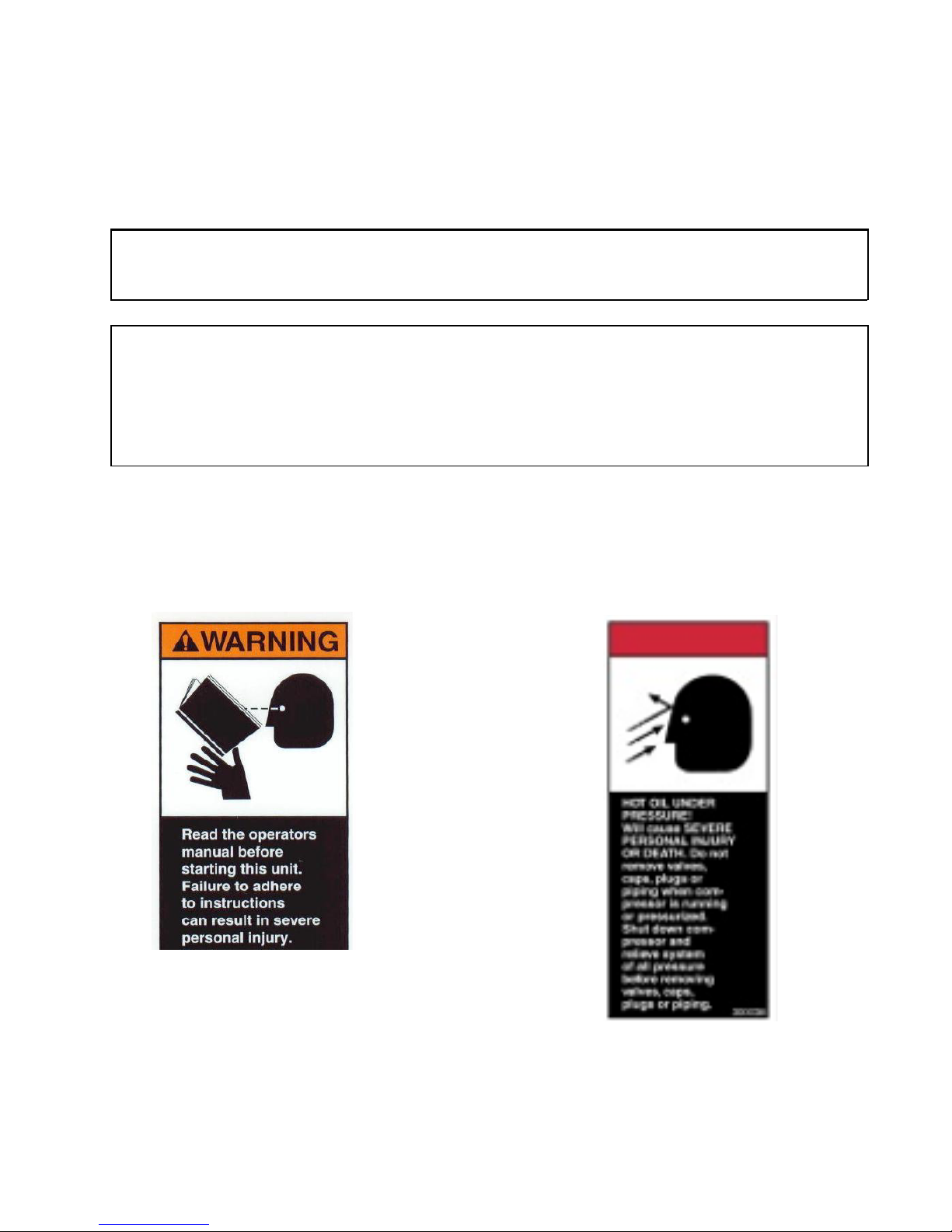
Compliments of warning decals are supplied with each unit. These decals are affixed to
the unit after it has been painted, prior to being put into service. The decals are placed so
as to be clearly visible to the user and service personnel.
P/N 300039 P/N 300038
13
SAFETY
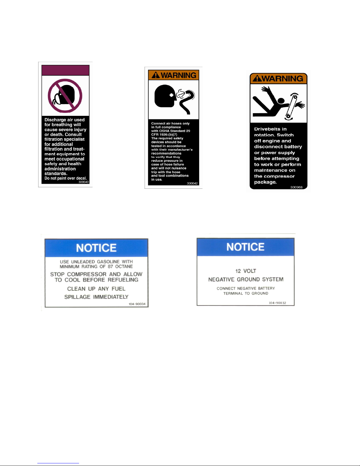
P/N 300040
P/N 104-90034
P/N 300042
P/N 300968
P/N 104-90032
14
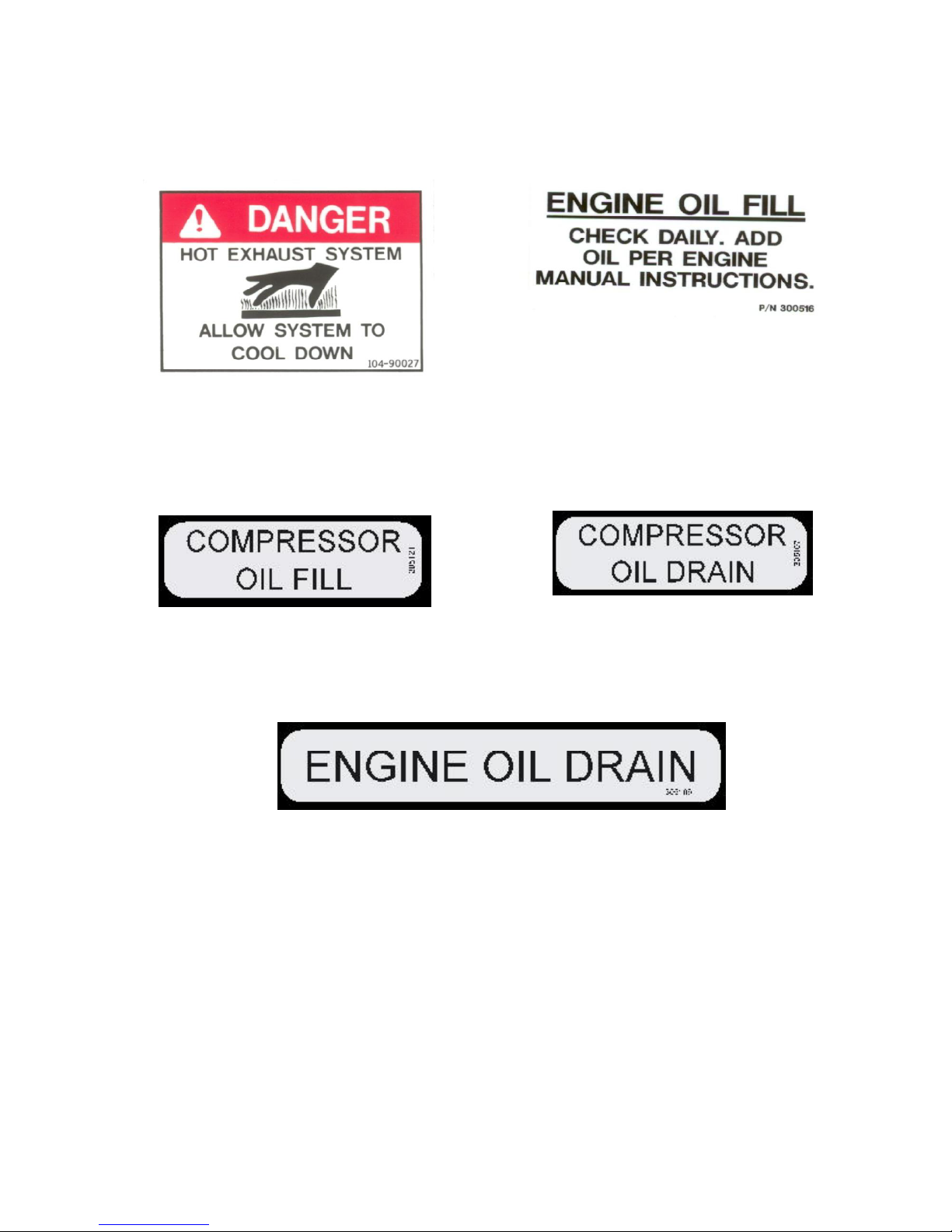
P/N 104-90027
SAFETY
P/N 300516
P/N 305121
P/N 305107
P/N 305106
15

DESCRIPTION OF COMPONENTS
POWER UNIT
The power unit used to drive the compressor is a gasoline engine that has been carefully
selected for its ability to provide an efficient and reliable source of power. For detailed
information on the power unit, refer to the Engine Operator’s Manual provided separately.
COMPRESSOR ASSEMBLY
The AC70 compressor assembly is a positive displacement, oil flooded, rotary screw type unit
employing one stage of compression to achieve the desired pressure. Components include a
housing (stator) two screws (rotors), bearings and bearing supports. The power source drives
the male rotor through the inlet housing. The male rotor drives the female rotor.
PRINCIPLES OF OPERATION
In operation, two helical grooved rotors mesh to compress air. Inlet air is trapped as the male
lobes roll down the female grooves, pushing trapped air along, compressing it until it
reaches the discharge port in the end of the stator and delivers smooth-flowing, pulse-free air
to the receiver.
During the compression cycle, oil is injected into the compressor and serves these purposes:
1. Lubricates the rotating parts and bearings.
2. Serves as a cooling agent for the compressed air.
3. Seals the running clearances.
LUBRICATION SYSTEM
Oil from the compressor oil sump, at compressor discharge pressure, is directed through the
oil cooling system, then the oil filter, and back to the compressor stator, where it is injected
into the compressor. At the same time oil is directed to the bearings and shaft seal of the
compressor. The oil-laden air is then discharged back into the sump. See Air/Oil Schematic in
the illustration section.
16

DESCRIPTION OF COMPONENTS
OIL SUMP
Compressed, oil-laden air enters the sump from the compressor. Most of the oil is separated
from the air as it passes through a series of baffles and defusing plates. The oil accumulates
at the bottom of the sump for re-circulation. Some small droplets of oil remain suspended in
the air and are passed on to the coalescer. See Discharge System in the illustration section.
SAFETY VALVE
The pop safety valve is set at 175 PSI and is located at the top of the air/oil sump. This
valve acts as a backup to protect the system from excessive pressure that might result from a
malfunction. See Discharge System in the illustration section.
OIL RETURN LINE
The oil that is removed by the coalescer accumulates at the bottom of the can and is returned
through an oil return line leading to the compressor. The oil return line also contains an
orifice and check valve located at the compressor in the elbow hose fitting. See Air/Oil
Schematic and Compressor Mounting System in the illustration section.
AIR/OIL COALESCER
The coalescer is self-contained within a spin-on housing and is separate of the sump. When
air is demanded at the service line, it passes through the coalescer, which efficiently provides
the final stage of oil separation. See Discharge System in the illustration section.
MINIMUM PRESSURE VALVE
The minimum pressure valve is located at the outlet of the coalescer head and serves to maintain a minimum discharge pressure of 55 PSIG in operation, which is required to assure adequate compressor lubrication pressure, and air/oil separation at the coalescer element. See
Discharge System in the illustration section.
OIL FILTER
The compressor oil filter is a full-flow replaceable element type and has a safety by-pass built
into it. This element screws directly to the compressor stator housing. See Compressor
Mounting System in the illustration section.
17

DESCRIPTION OF COMPONENTS
COMPRESSOR COOLING SYSTEM
The compressor cooling system consists of an oil cooler, electric fan and motor. See Cooler
and Parts System in the illustration section.
An automated thermostatic control system maintains a continuous temperature check of the
lubricant. The fan sensor trips a normally open relay which sends power to the fan motor
once compressor oil temperature reaches 190°F. The fan sensor stops power to the fan
motor once the compressor oils temperature drops to 160°F.
INSTRUMENT PANEL AND OPERATING CONTROLS
The instrument panel contains all the necessary gauges and instruments for operation and is
located outside of the main enclosure The following is an explanation of their use. See
Electrical System & Wiring Diagram in the illustration section.
1. Start (key)
The starter switch is used to electrically energize the engine starter motor solenoid to
begin cranking of engine.
2. Choke (Gasoline Engine Only)
The choke is used to provide a richer fuel mixture to the engine for cold starts. Pulling the choke cable out increases the fuel mixture. As the engine warms up, the
choke should be pushed inward. The engine should operate without choking as soon
as possible after starting, to avoid flooding or dilution of lubricating oil.
3. Hourmeter
The hourmeter records the total number of operating hours. It serves as a guide
towards following the recommended inspection and maintenance schedule.
4. Pressure Meter
The pressure meter displays compressor discharge air pressure. This meter also has a
shutdown feature and will shutdown the engine if the discharge air pressure reaches 150
psi.
5. Temperature Meter
The temperature meter displays compressor discharge air temperature. This meter also
has a shutdown feature and will shutdown the engine if the discharge air reaches 250°F.
18
 Loading...