

MMD Equipment 185S-6C1 User Manual
Preface
Thank you for having selected our “AIRMAN” product.
◆ This manual explains about the proper operation and daily inspection and maintenance of this
machine.
◆ In order to use a machine safely, people with sufficient knowledge and sufficient technology need to
deal with it.
◆ Before operating the unit, read the manual carefully, fully understand its operation and
maintenance requirement. Maintain “SAFETY OPERATION AND PROPER MAINTENANCE OF
THE UNIT”.
Be sure to follow safety warnings and cautions given in the manual.
Unsafe operation could cause serious injury or death.
◆ For details of handling, maintenance and safety of the engine, see the Engine Operation Manual.
◆ Keep the manual available at all times for the operator or safety supervisor.
◆ If the manual is lost or damaged, place an order with your dealer for another copy.
◆ Be sure that the manual is included with the unit when it is handed over to another user.
◆ There may be some inconsistency in detail between the manual and the actual machine due to
improvements of the machine. Ask your dealer if you have any questions or problems.
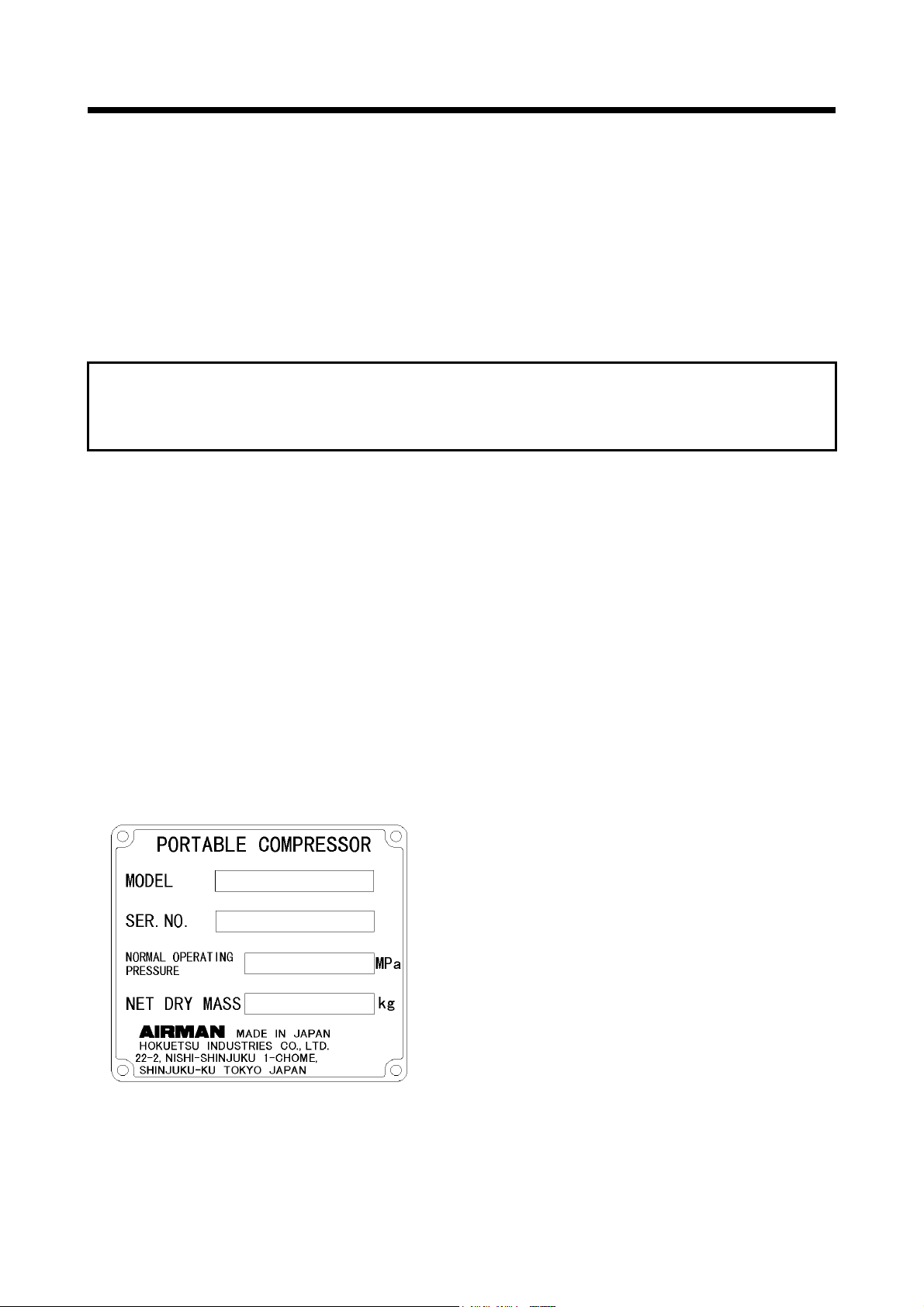
◆ If you have any questions about the unit, please inform us the model and serial number. A plate
stamped with the model and serial number is attached to side of the unit.
◆ Each illustrated figure (Fig.) has a number of 7
digits (for instance, A990054) at the right
bottom. This number is not a part number, but
it is used only for our reference number.
A990054

Table of Contents
1. Safety -------------------------------------------------------------------------------------------------------- 1-1
1.1 Caution before Operation ---------------------------------------------------------------------------------------------------- 1-2
1.2 Caution during Operation ----------------------------------------------------------------------------------------------------
1.3 Caution during Inspection and Maintenance ----------------------------------------------------------------------------
1.4 Safety Warning Labels -------------------------------------------------------------------------------------------------------
2. Part Names ------------------------------------------------------------------------------------------------ 2-1
2.1 Internal Components and Part Names ----------------------------------------------------------------------------------- 2-1
3. Installation -------------------------------------------------------------------------------------------------- 3-1
3.1 Transportation ------------------------------------------------------------------------------------------------------------------ 3-1
3.2 Towing the Unit -----------------------------------------------------------------------------------------------------------------
3.3 Installation -----------------------------------------------------------------------------------------------------------------------
4. Operation ---------------------------------------------------------------------------------------------------- 4-1
4.1 Instrument panel --------------------------------------------------------------------------------------------------------------- 4-1
4.2
Lubricating oil・Coolant・ Fuel
4.3 Check before Starting Unit --------------------------------------------------------------------------------------------------
4.4 Operation -----------------------------------------------------------------------------------------------------------------------
4.5 Stopping ------------------------------------------------------------------------------------------------------------------------
4.6
Capacity Control Device
------------------------------------------------------------------------------------------------ 4-16
---------------------------------------------------------------------------------------- 4-4
5. Periodic Inspection/Maintenance ------------------------------------------------------------------ 5-1
5.1 Important Items as Periodic Inspection and Maintenance or after Maintenance ------------------------------- 5-1
5.2 Daily Inspection and Operation Log ---------------------------------------------------------------------------------------
5.3 Periodic Inspection List -------------------------------------------------------------------------------------------------------
5.4 Periodic Replacement of Parts ---------------------------------------------------------------------------------------------
5.5 Maintenance Items ------------------------------------------------------------------------------------------------------------
6. Maintenance ---------------------------------------------------------------------------------------------- 6-1
6.1 Maintenance of Battery ------------------------------------------------------------------------------------------------------- 6-1
6.2 Troubleshooting ----------------------------------------------------------------------------------------------------------------
7. Storage of the Unit -------------------------------------------------------------------------------------- 7-1
7.1 Preparation for Long-term Storage ---------------------------------------------------------------------------------------- 7-1
8. Specifications -------------------------------------------------------------------------------------------- 8-1
8.1 Specifications ------------------------------------------------------------------------------------------------------------------- 8-1
8.2 Outline drawing ----------------------------------------------------------------------------------------------------------------- 8-2
9. Wiring Diagram ------------------------------------------------------------------------------------------ 9-1
10. Piping Diagram -------------------------------------------------------------------------------------------10-1
1-5
1-7
1-10
3-2
3-2
4-6
4-11
4-15
5-2
5-3
5-5
5-6
6-3
1.Safety
This manual explains and illustrates general requirements for safety.
Read all safety requirements carefully and fully understand the contents before starting the machine.
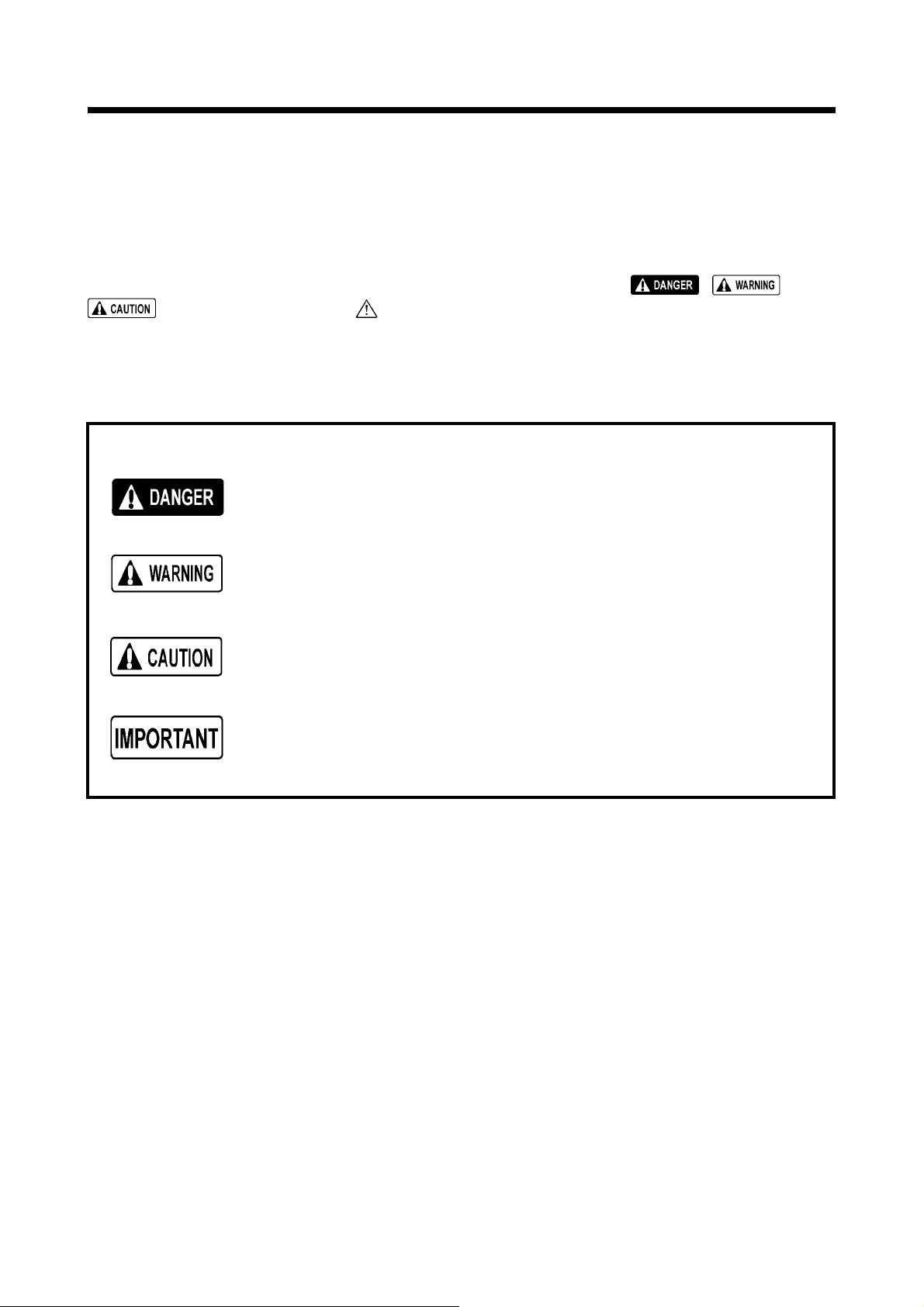
For your better recognition, according to the degree of potential danger, safety messages are classified into three hierarchical categories, namely, , , and
with a caution symbol -attached to each message.
When one of these messages is shown, please take preventive measures and carry out
“SAFETY OPERATION AND PROPER MAINTENANCE OF THE UNIT”.
Follow warnings mentioned in this manual. This manual does not describe all
safety items. We, therefore, advise you to pay special attention to all items (even
though they may not be described in the manual) for your safety.
DANGER indicates an imminently hazardous situation which,
if not avoided, will result in death or serious injury. This
signal word is to be limited to the most extreme situations.
WARNING indicates a potentially hazardous situation which, if
not avoided, could result in death or serious injury.
CAUTION indicates a potentially hazardous situation which, if
not avoided, may result in minor or moderate injury. It may
also be used to alert against unsafe practices.
IMPORTANT indicates important caution messages for the
performance or durability of the unit.
1-1
1.Safety
1.1 Caution before Operation
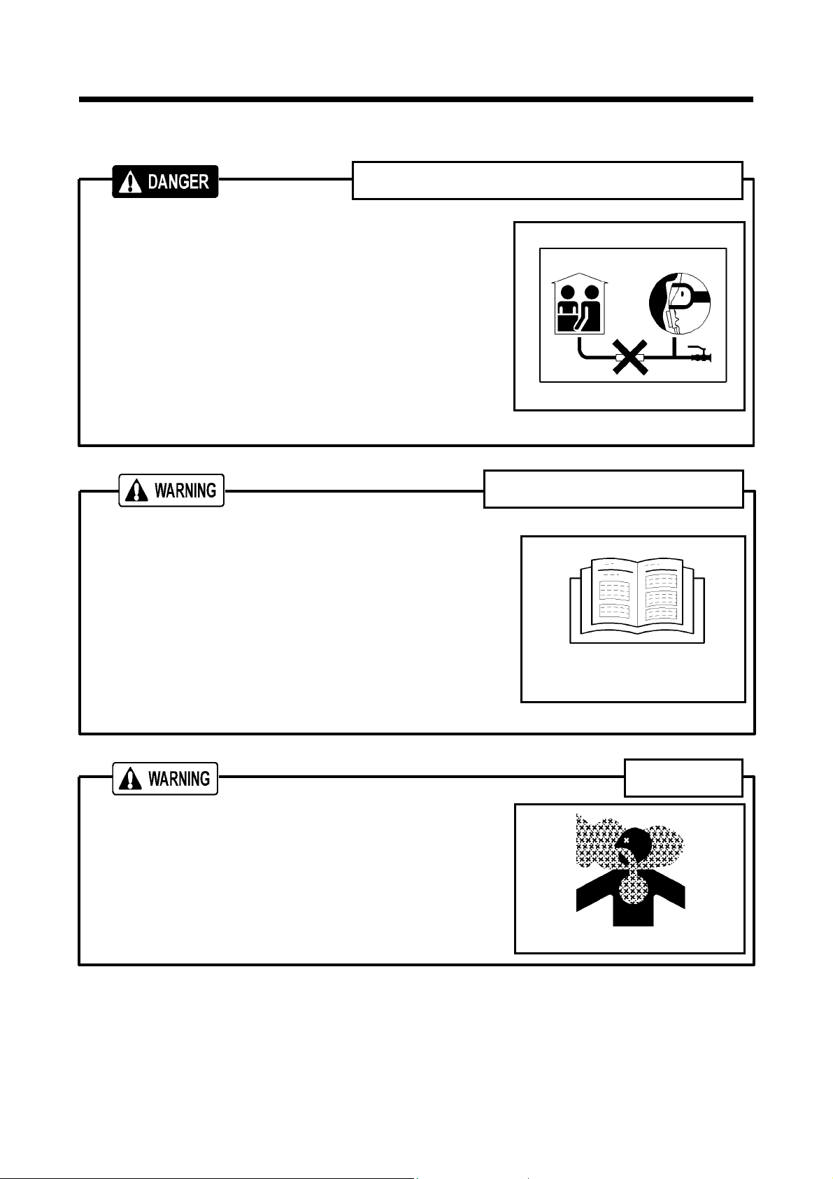
Air pressurized construction method prohibited
Never use the unit directly or indirectly for the following pur-
poses:
Never use the unit for respirator equipment by which com-
pressed air is supplied for human consumption. The compressed air contains carbon monoxide and other contaminants,
and such air may cause serious injury or even death if used by
a person for respiration.
This compressor is not designed for air pressurized construc-
tion method and underwater diving jobs.
Never use compressed air for human consumption such as
pressurizing diving air tanks. Consumption of compressed air
can cause death while diving.
Read each instruction plate which is displayed in the manual or
on the unit carefully, understand its content and follow the
indications thereof.
Keep the Safety Warning labels clean. When they are dam-
aged or missing, apply new ones.
Do not modify the machine without prior approval. The safety
may be compromised, functions may be deteriorated, or machine life may be shortened.
Never use the unit for the purpose of compression of gases
other than air, or as a vacuum pump. Otherwise, serious accidents may occur.
TR0201
Follow the safety instructions
TR0086
Exhaust gas from the engine is poisonous, and could cause
death when inhaled.
Avoid using the machine in an insufficiently ventilated building
or tunnel.
1-2
Ventilation
PC002
1.Safety
Keep flames away from battery.
Battery may generate hydrogen gas and may explode.
Battery electrolyte is dilute sulfuric acid.
In case of mishandling, it could cause skin burning.
When you deal with a battery, please be sure to wear protec-
tion implements, such as protection glasses and a glove.
Dispose of battery, observing local regulations.
Handling battery
D004
TR0093
Cautions of hose attachment and removal
Piping or the hose from this machine service valve should use
what can be borne enough for the discharge pressure of this
machine.
Please connect piping or a hose to this machine service valve
firmly before operation and during operation. If the connection
part is loosening, there is a possibility of piping or a hose
separating and getting seriously injured.
Please remove after closing a service valve and extracting
pressure remained, in case piping or a hose is removed. If
pressure remained should remain, a near thing blows away or
there is a possibility of a hose whipping, causing a phenomenon and getting seriously injured.
In order to use it safely, please read the handling of the work
tools often used.
When handling machine, do not wear;
loose clothes
clothes with unbuttoned sleeves
hanging tie or scarf
accessories such as dangling jewelry
Such outfit could be caught in the machine or dragged in the
rotating portion of the machine, and this could cause a serious
injury.
TR0088
TR0088
TR0303A
Safety outfit
TR0084
1-3

1.Safety
Maintain both physicl and mental health
Do not operate the machine when you are tired or drunk or under the influence of drugs. Otherwise, a
hasty conclusion or careless handling may cause unexpected injury or accident.
Manage your physical and mental health and be cautious in handling the machine.
Protection equipments
Please wear protection implements, such as a helmet, protec-
tion glasses, earplugs, safety shoes, a glove, and a protection-against-dust mask, according to the contents of work for
safety.
TR0085
Safety fittings
Have first-aid boxes and fire-extinguishers near the unit ready
for emergency situations such as injuries and a fire.
It is advisable to have a list of phone numbers of doctors, am-
bulance and the fire department available in case of emergency.
Safety around the machine
Such things as unnecessary equipment and tools, cables, hoods, covers and pieces of wood which
are a hindrance to the job, have to be cleaned and removed. This is because operators and/or personnel nearby may stumble on them and may be injured.
Place safety enclosures at the entrance of and around working site to prevent children or outside
people from entering the site.
TR0096
1-4
1.Safety
1.2 Caution during Operation
Do not replenish compressor oil during operation
Do not, under any circumstance, open the oil filler cap of
separator receiver tank while running or immediately after
stopping operation.
It is very dangerous because the oil filler cap could be blown
off and high temperature compressed air and oil could jet out
from the filler port, and cause serious injury.
Draining during operation prohibited
Do not, under any circumstance, open the portions below dur-
ing operation:
Separator receiver tank drain valve
Coolant drain valve and plug
Engine oil drain valve
Oil cooler drain valve
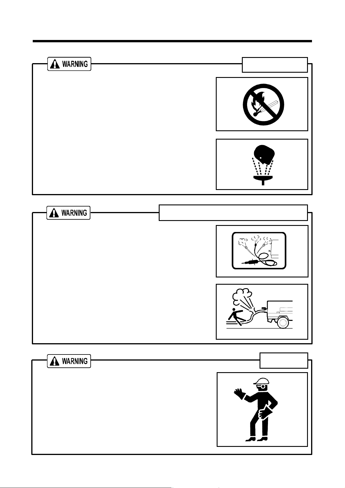
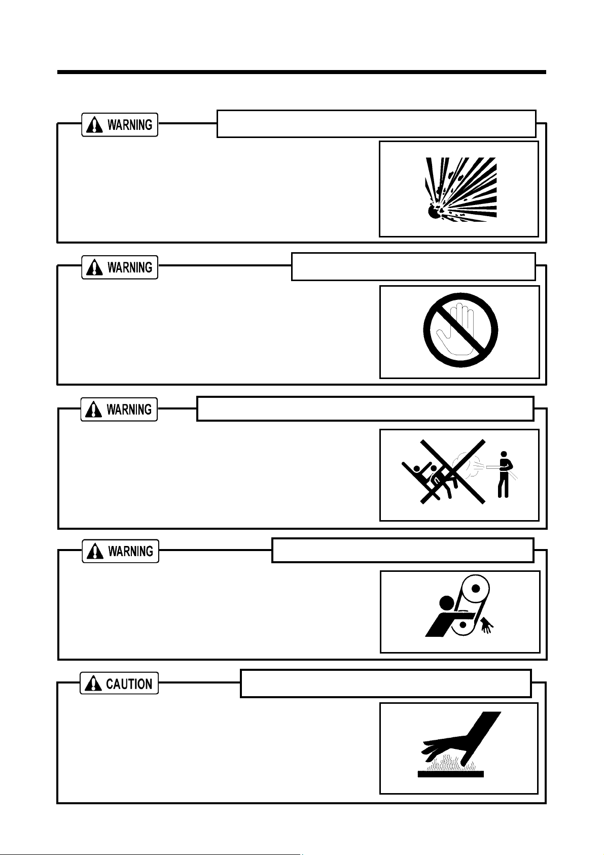
Never direct the compressed air to people and foods
W010
PK0028
Never blow compressed air directly at people.
Scattered impurities, dust, or foreign objects in the compressed
air may cause skin and eyes to be seriously injured.
Blowing compressed air on food is prohibited.
Hands off from rotating parts and belts
Keep hands off from the rotating portion or belts while running.
It could cause serious injuries if hands should be caught in.
Do not remove radiator cap during operation
Do not, under any circumstance, open the radiator cap while
running or immediately after stopping operation. Otherwise high
temperature steam jets out and this could cause scalding.
TR0092
TR0304
H990432
1-5

1.Safety
Operation with compressed air supply port opened
Do not operate the machine with service valves and relief
valve open unless air hoses and/or pipes are connected.
High-pressurized air blows out and its air pressure could
cause injury to the people nearby.
When the machine has to be unavoidably temporarily
operated with its port open, be sure to mount a silencer to
reduce noise and wear protective materials such as
earplugs to prevent damage to hearing.
Never work nearby hot portions of the machine while it is
running.
Do not touch hot portions of the machine while inspecting the
machine when running.
Such parts as engine, exhaust manifold, exhaust pipe,
muffler, radiator, oil cooler, compressor, piping, separator
receiver tank, and discharging pipe are especially hot, so
never touch those parts, because it could cause serious
burns.
Compressor oil, coolant water, and engine oil are also very
hot and dangerous to touch.
Avoid checking or refilling them while the unit is running.
is prohibited
D003
Do not touch hot parts
H990432
Fire prevention
Do not, under any circumstance, bring lit cigarettes or
matches near such oils as engine oil and compressor oil, etc.
They are extremely flammable and dangerous, so be careful
when handling.
Refilling oils should be done in an outdoor well-ventilated
place.
Refuel after stopping the engine, and never leave the fuel
nearby the machine. Do not spill. It may cause a fire. When
it is spilt, wipe it up completely.
Such parts as muffler and exhaust pipe can be extremely
hot. Remove twigs, dried leaves, dried grass and waste
paper, etc. from the exhaust outlet of the muffler.
Keep a fire extinguisher available by the machine in case of
a fire.
W005
1-6
1.Safety
g
l
1.3 Caution during Inspection and Maintenance
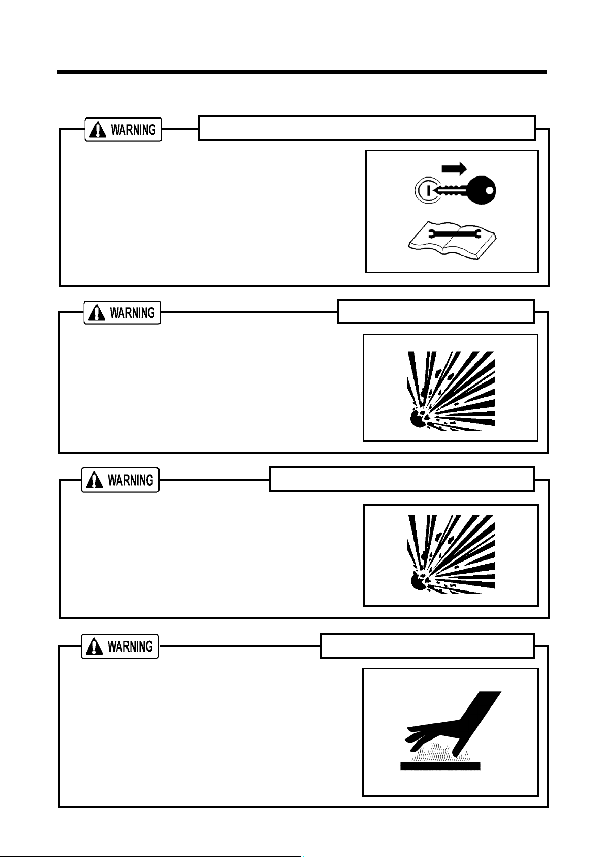
Remove the starter key from the starter switch before
starting inspection, and hang up a “Now Checking and under
Maintenance” tag where it can be easily seen. The checker
must keep the key during checking and maintenance.
Remove the negative (–) side cable from the battery.
If the above procedure is neglected, and another person
starts operating the machine during check or maintenance, it
could cause serious injury.
When you refill the separator receiver tank with compressor
oil, stop the engine, and make sure that the pressure gauge
indicates 0MPa and there is no residual pressure in it, and
then gradually loosen the oil filler cap for refilling oil.
Note residual pressure in the separator receiver tank could
force both extremely hot compressed air and oil to jet out
and you may be scalded or seriously injured.
Hang a “Now Checking and under Maintenance” ta
Refilling of compressor oi
Be careful of high-pressurized air blowout
SY001
W010
After stopping the engine, make sure that pressure gauge
indicates 0MPa. Even when the gauge shows 0MPa, open a
service valve and further do not fail to make sure that there
is no residual pressure in the air piping. Then start such a
job as repair and maintenance.
Residual air under pressure will blow off and severely injure
operator.
After stopping the engine, confirm that the pressure gauge
indicates 0MPa and there is no residual pressure in it, then
open the drain valve gradually to drain the compressor oil.
Note residual pressure in the separator receiver tank could
force both extremely hot compressed air and oil to jet out
and you may be scalded or seriously injured.
W010
Draining separator receiver tank
H990432
1-7
1.Safety
w
i
g
Be sure to stop the engine and remove the starter key
whenever the tension of the fan belt is to be adjusted.
Remove the negative (–) side cable from the battery.
If the machine is running, it might catch the operator’s hand
into the fan belts, and this could cause a serious injury.
Be sure to stop the engine and remove the starter key
whenever check or maintenance work is carried out near
the cooling fan.
If the cooling fan is rotating, it may catch the operator or part
of his body into the fan, and it could cause a serious injury.
Adjusting tension of fan belt
TR0304
Hands off from cooling fan
W009
Cleaning by air-blo
When cleaning dust accumulated in such devices as the
air-filter, by blowing compressed air, wear safety glasses,
etc. to protect your eyes.
It is recommended to use a lamp with safety guard fitted
where the site is dark.
Operating the machine gropingly or by relying on one’s
intuition could cause unexpected accidents.
Any lamps without safety guard are not recommended since
they can be broken and they could ignite flammables such
as fuel, etc.
L
hting apparatus
M003
TR0206
1-8
1.Safety
l
Be sure to stop the engine, and let the coolant water
sufficiently cool down before draining it.
If the drain valve is opened before the coolant water is
cooled enough, hot water could jet out, and it could cause
scalding.
After stopping the engine, wait for 10 to 20 minutes until
the engine oil cools off. Then check the level of the engine
oil, or refill or drain the oil.
Engine oil is very hot and highly pressurized during or just
after the operation. Hot oil could blow out of the tank and
can cause scalding.
Opening coolant water drain valve cap
Refilling or draining of engine oi
H990432
H990432
Fear of fire
Be sure to perform the periodical check of compressor oil
and oil separator.
Neglecting checks could cause overheat of the oil,
resulting in a fire.
Disposal of waste liquid, etc.
H990433
Waste liquid from the machine contains harmful material. Do not discharge it onto the ground or into
the river, lake or sea. Such material will contaminate the environment.
Be sure to use a container to hold the waste liquid from the machine.
Be sure to follow the designated regulations when disposing of oil, fuel, coolant (antifreeze), filter,
battery or other harmful materials.
1-9
1.Safety
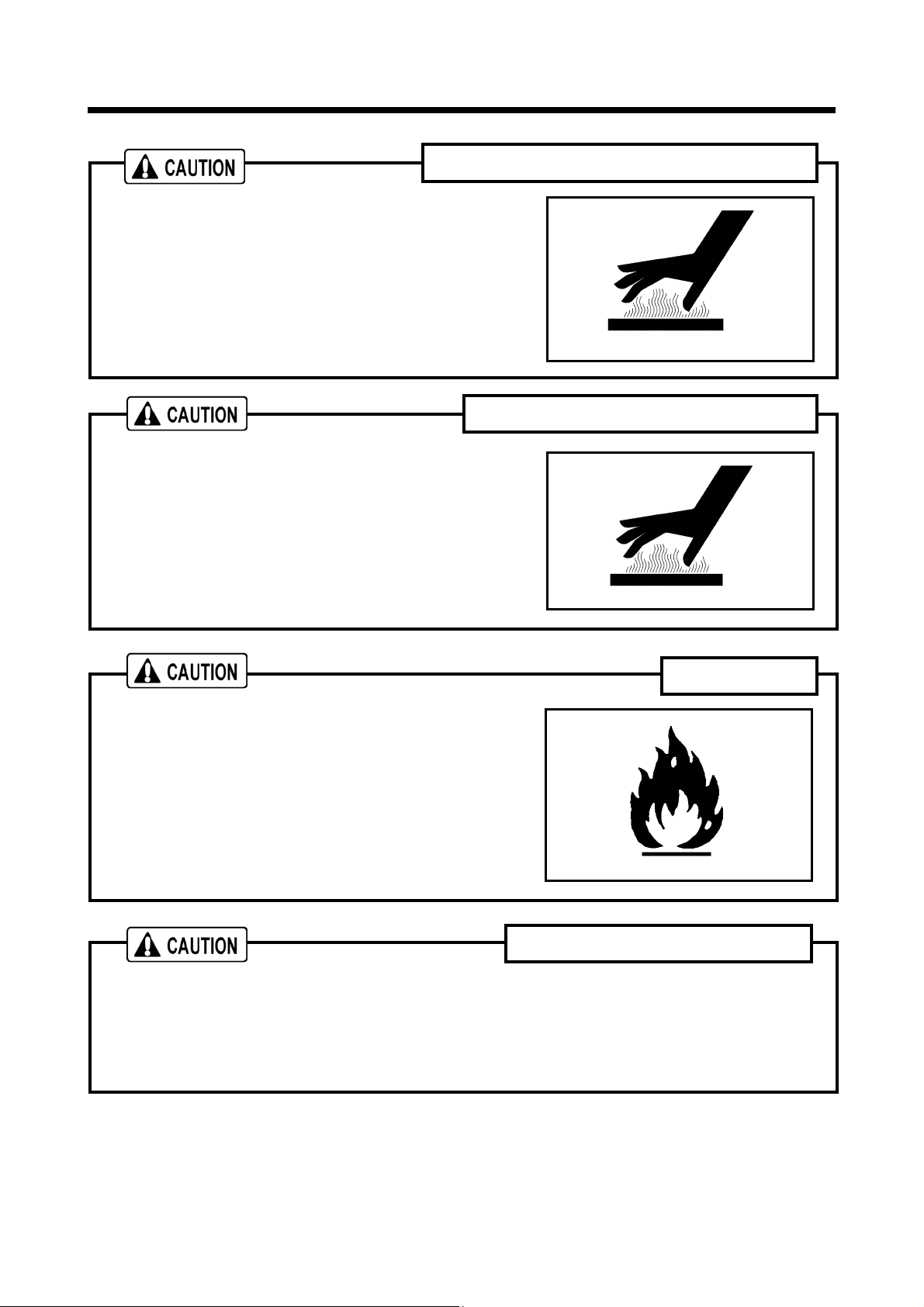
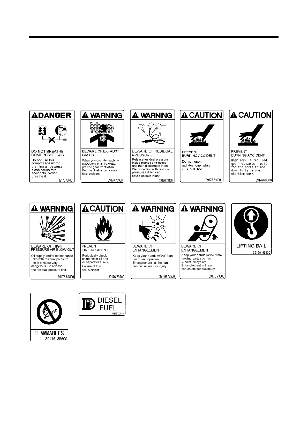
1.4 Safety Warning Labels
Following labels are attached to the machine.
Keep them clean at all times. If they are damaged or missing, immediately place an order with your
nearest dealer for replacement. Part numbers are indicated on the lower right corner of the label.
Adhere a new one to the original location.
1 2 3 4 5
6 7 8 9 10
11 12
1-10
1.Safety
V
V
A
A
B
The pasting position of safe warning label is as follows.
2
070318
4
11
12
10
8
7 6
3
1
5
5 9
1-11
EIW-A
8
EIW-B
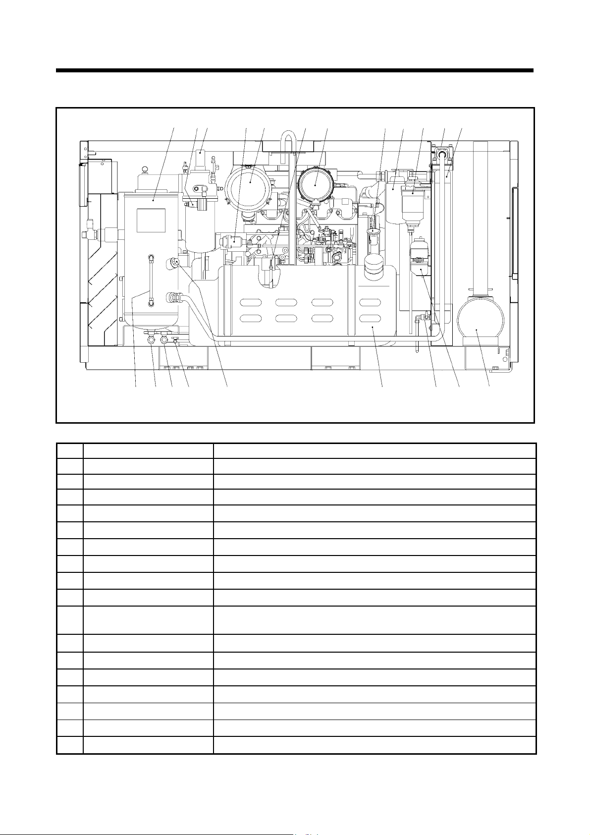
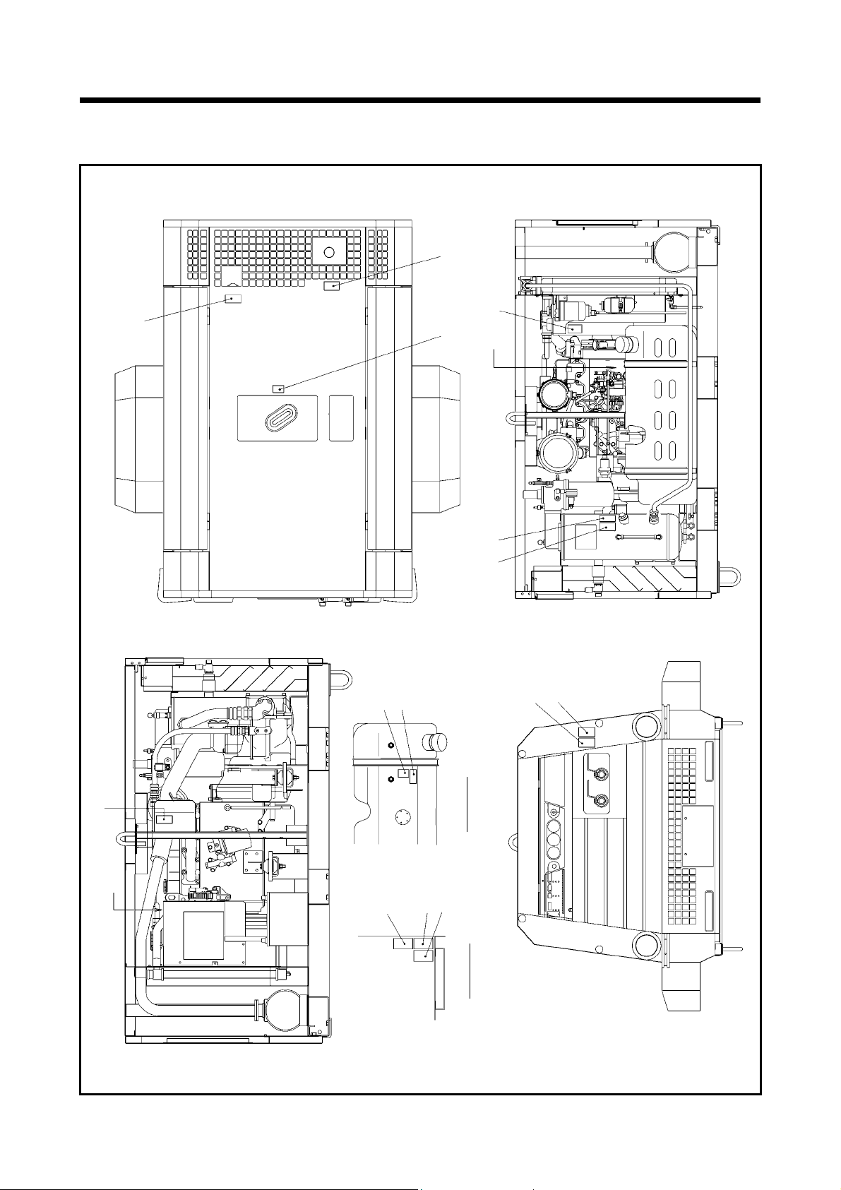
2.Part Names
A
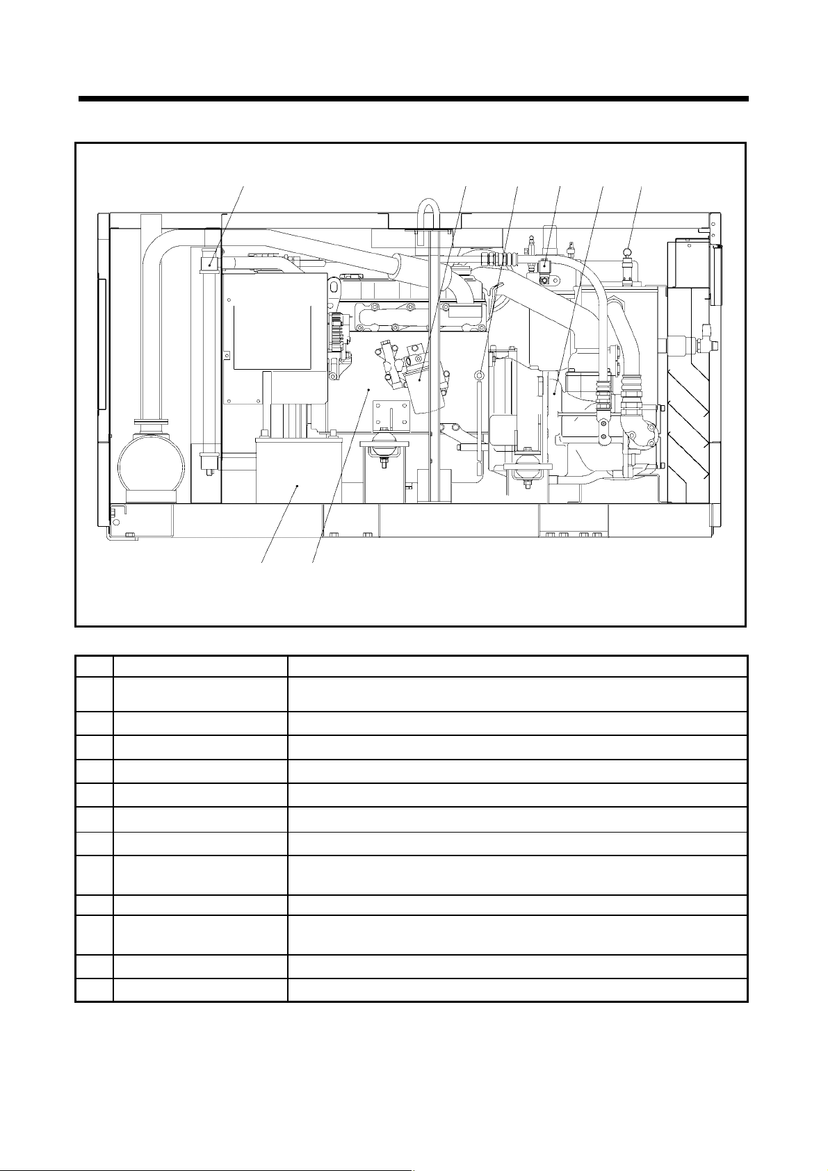
2.1 Internal Components and Part Names
21 20 19 18 17 16 15 14 13
1 2 3
4 5 6 7
8 9 10 11 12
070302
No. Description Function
1 Separator receiver tank
Pressure regulator
2
3 Pressure control valve
4 Speed regulator
5 Air filter(For compressor)
6 Engine oil level gauge
7 Air filter(For engine)
8 Engine oil filler port
9 Compressor oil filter
Fuel filter
10
(sedimenter built-in type)
11 By-pass valve
12 Oil cooler
13 Exhaust muffler Equipment which muffles an engine exhaust sound.
Reserve tank
14
15 Oil cooler drain valve
16 Fuel tank
17
Compressor oil filler port For supplying and replenishing compressor oil.
For separating compressor oil from compressed air sent into the tank.
For regulating intake air volume.
For keeping the receiver tank pressure higher than 0.4MPa in the tank.
For regulating compressor revolution speed.
For filtering the dust floating in the intake air.
For checking engine oil level.
For filtering the dust floating in the intake air.
For supplying and replenishing engine oil to engine.
For filtering compressor oil circulating in the system.
For filtering dust and foreign matter mixed or to be mixed in the
fuel oil.and for separating water mixed or to be mixed in the fuel oil.
For keeping compressor oil at proper temperature.
For cooling compressor oil circulating in the system.
For feeding cooling water.
For draining condensate accumulated at the bottom of oil cooler.
For storing diesel fuel oil.
2-1
2.Part Names
A
22 23
24 25
26 27
29 28
No. Description Function
18 Fuel tank drain valve
19 Engine oil drain valve
Compressor oil drain valve
20
21
Compressor oil level gauge
22 Radiator
23 Engine oil filter
24 Coolant drain valve
Solenoid valve for AUTO
25
IDLE mode
26 Air-end
27 Safety valve
28 Engine
Battery
29
For draining condensate and water accumulated at the bottom of
the fuel tank.
For draining engine oil for replacement of it and for maintenance.
For draining compressor oil from separator receiver tank.
Scale for measuring compressor oil level.
For cooling the coolant for engine because it is water-cooled.
For filtering engine oil.
For draining condensate from engine.
Control device for reduction of power under unloaded operation
For compressing intake air.
For releasing compressed air to the atmosphere when the pressure rises
higher than the rated pressure.
For driving the compressor.
For electrically starting engine.
070303
2-2
3. Installation
T
A
3.1 Transportation
When loading and unloading unit, be sure to use the lifting bail provided on the center of the unit top.
Never get under the unit which is lifted up, because it is very dangerous.
When unit is transferred or moved from working site, be sure to place it on truck bed, and fasten it by
ropes at the front eye and rear stand. Also be sure to put a set of chocks to fix its wheels firmly on the
truck bed.
Never lift unit which is still in operation, or it could cause critical damage to each component or lead to
serious accident.
When lifting unit up, make sure that all the fixing bolts on the bonnet are surely tightened because it is
feared that the unit may fall.
If towing unit : Make sure machine is towed level.
Check tire pressure and tire condition before towing.
Attach safety chains and use correct tow hitch.
Check operation of lights and brakes before towing.
Check wheel lug nuts for proper torque.
ransportation
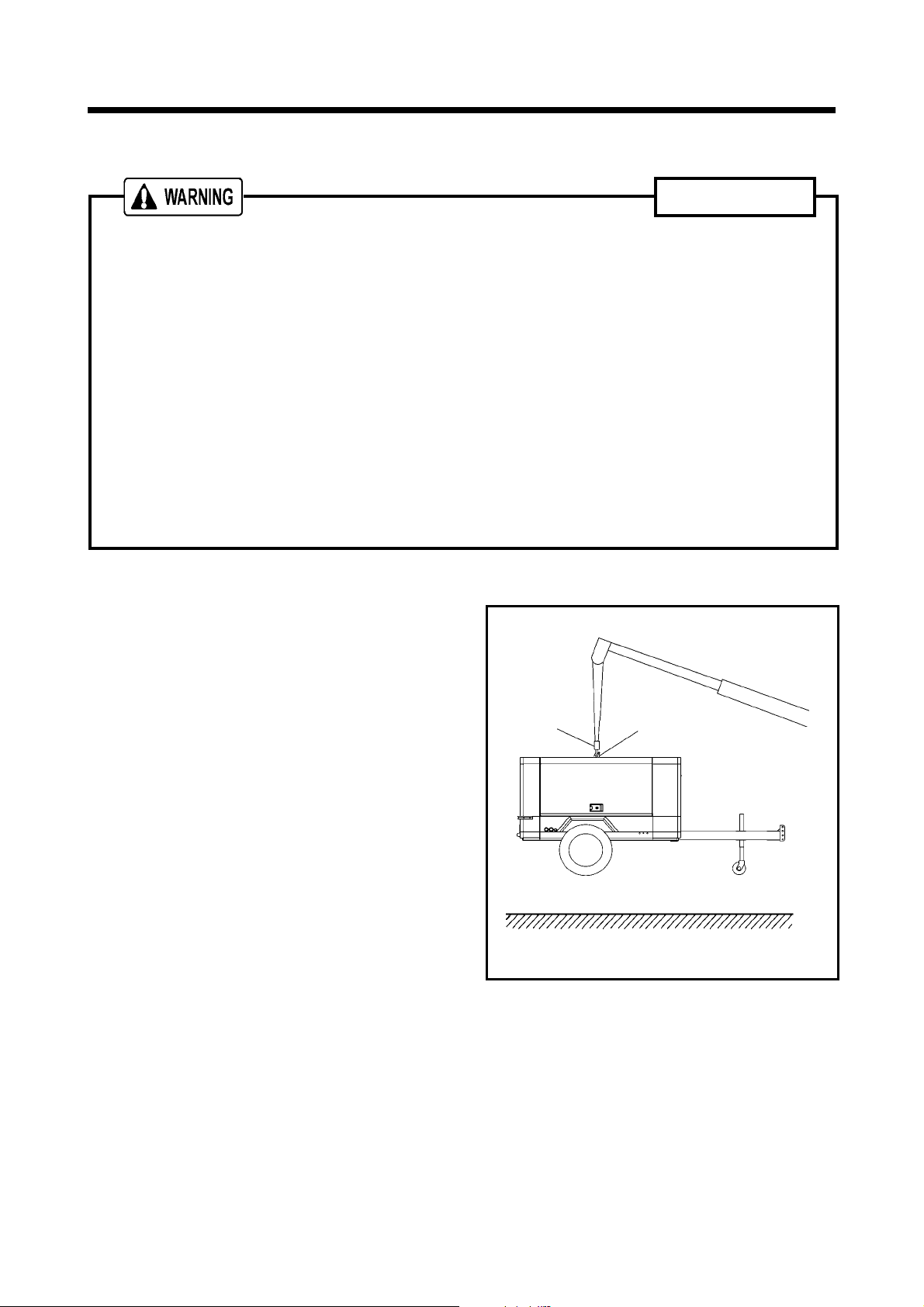
3.1.1 Lifting up
① Before lifting the unit up, make sure to check
the lifting bail for any crack and loosened
bolts.
② Connect the hook“1” of the crane or shackle
with lifting bail“2”eye fitted at the top center
of the unit, and make sure that there is no
person standing around the unit. Then
perform hoisting operation.
③ Select a truck or a crane with capacity
sufficient for weight and size of the unit by
referring to the values shown in Chapter 8
“Specifications“ of the manual.
1
2
070190-1
3.1.2 Lowering the unit from the truck bed pulling down
Lower the unit down onto a level place which can sustain the weight of the unit.
After placing the unit down, put chocks to lock the wheels before unfastening the crane’s shackles.
3-1
3. Installation
3.2 Towing the Unit
Before towing the unit, check the following points and be sure to repair failures, if any:
Air-pressure in the tires.
Loose wheel bolts or nuts.
Abnormal wear or damage to the tires.
Damage of drawbar.
Be sure to use a vehicle with enough capacity to tow the unit in operating weight.
Do not tow the unit without unfastening tool, equipment, and hoses.
Keep hands and fingers clear during hook-up or unhooking drawbar.
If you do not follow the above instructions, it could cause serious injury or big damage.
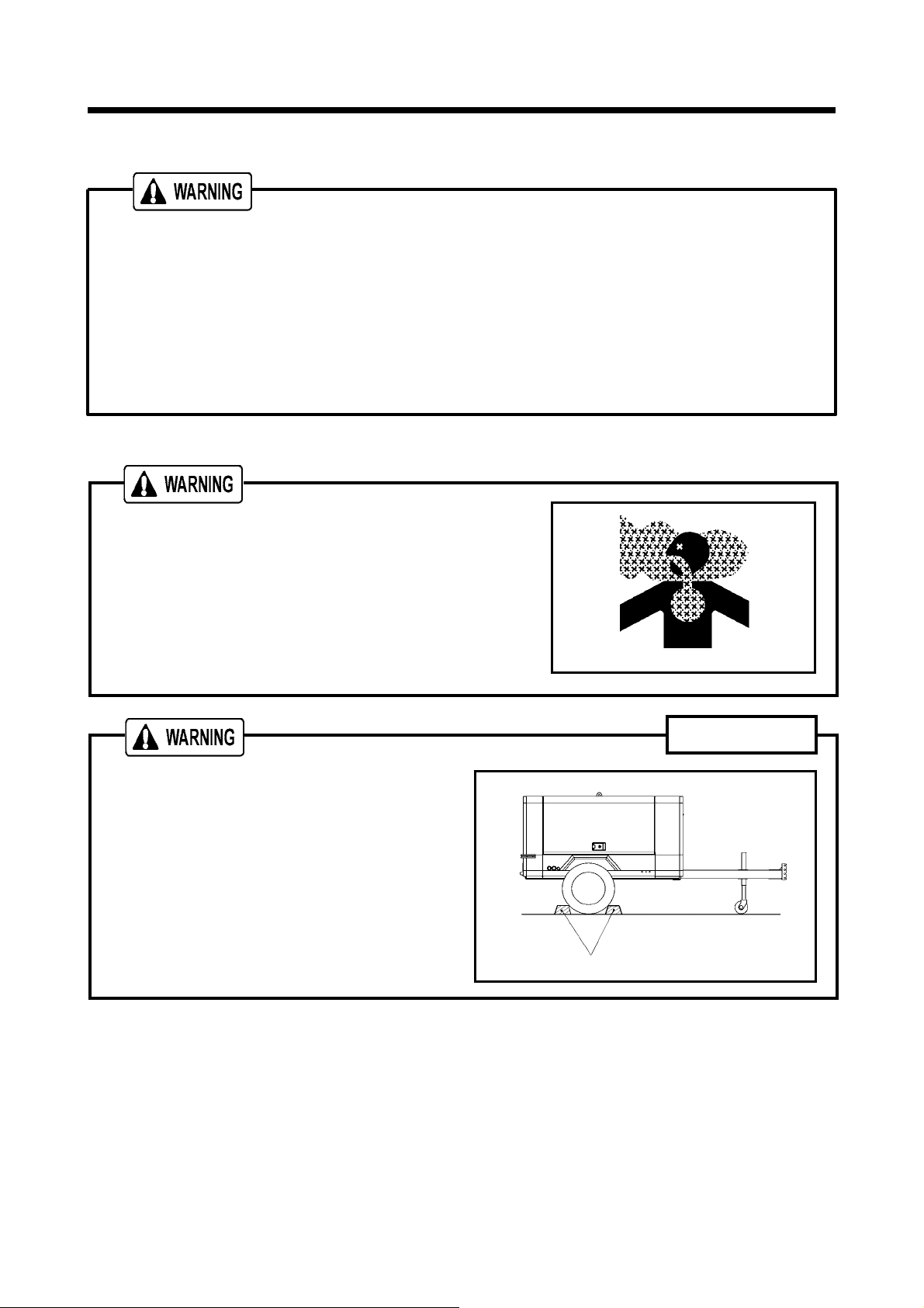
3.3 Installation
Exhaust gas from the engine is poisonous, and could cause
death when inhaled.
Avoid using the machine in an insufficiently ventilated
building or tunnel.
Do not position the exhaust gas outlet in direction of a person
or a house.
Installation
The machine has to be parked horizontally on a
level place.
In case the machine has to be parked on a slope,
place it across grade so that the machine does
not tend to roll downhill.
Following grades on a slope for the machine are
recom- mended within 15° degrees.
In case of trailer type, be sure to put one set of
chocks “1” to the wheels.
A070192-1
1
The machine should be operated in following conditions:
Ambient temperature
Humidity
Altitude
・・・・・・・・・・・・・・・・・
・・・・・・・・・・・・・・・・・・
・・・・・・・
5°F to 104°F( -15℃~+40℃)
Less than 90%
Lower than 1,500 m above sea level
Install the machine in a place with good ventilation, lower temperature and with surroundings as
dry as possible.
If more than two machines are placed parallel in operation, keep enough distance so that exhaust
air from one machine does not effect the other one.
Also, a machine has to be installed in the environment where fresh air is always available.
Keep enough space around the unit for inspection and maintenance access.
3-2
4. Operation
A
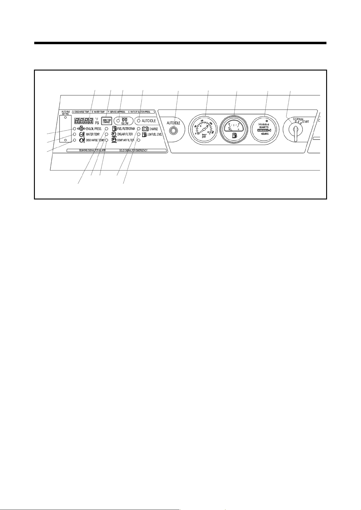
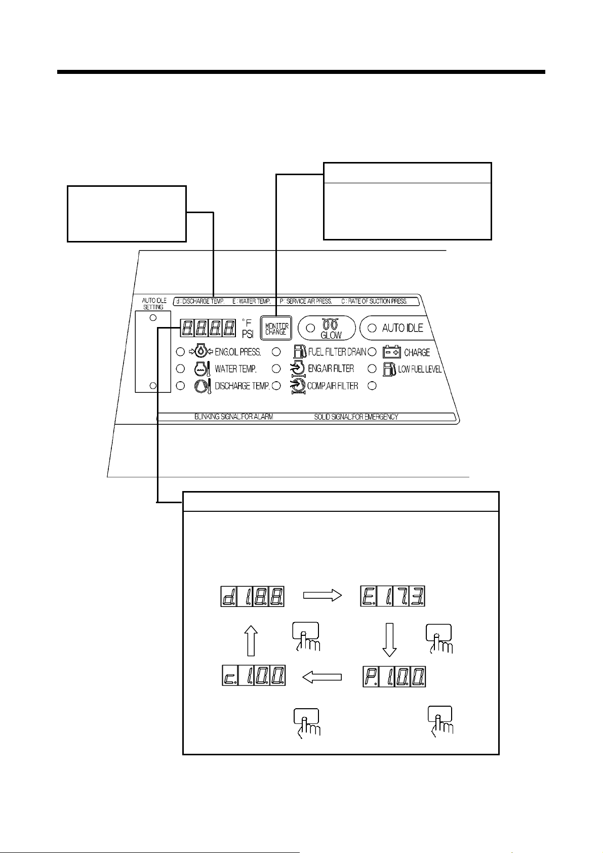
4.1 Instrument panel
17
16
15
1. Digital monitor indicator (temperature/pressure)
2. Selector switch fordigital monitor indication
3. Auto idle switch
4. Discharge air pressure
5. Fuel level gauge
6. Hour meter
7. Starter switch
14 13
1 2 8 9 3 4 5 6 7
12 11 10
<Indicator lamp>
8.
Glow
9.Auto idle
<Warning lamp>
10. Charge
Compressor air filter clogging
11.
12.
Engine air filter clogging
<Emergency stop lamp>
13. Low fuel level
14. Fuel filter drain
15. Discharge air temperature
16. Water temperature
17. Engine oil pressure
070178
4-1
4. Operation
A
A
A
4.1.1 Digital monitor indicator
Place starter switch “ON” and then digital monitor indicator goes on.
Press monitor selector switch for selection of digital monitor display.
These items indicate
the item which is
displayed on digital
monitor.
fter start, d( discharge air temperature) is displayed. It is
possible to select such item by pressing the selector switch:
t each press, d (discharge air temperature)→E (Engine
temp.) →P (discharge pressure) → C (Load factor) are selected.
[Discharge air temperature] [Engine water temperature]
[Press Load factor]
Digital monitor
Digital monitor selector switch
Even during operation it is
possible to display the item
which is required to be
checked.
Push
[Discharge pressure]
Push
070272-1
Push
Push
4-2
 Loading...