

M&M RWB series User Manual

&
M&M Refrigeration, Inc.
Computer Control System
Screw Compressor Control
RWB Series
Retro Fit Panel

Standard Screw Compressor - RWB Series
Copyright protection claimed includes all forms and matters now and hereinafter granted protection by statutory or judicial law, including unlimited protection for screen images generated
from the software programs. Such images include but are not limited to windows, icons, and
report displays.
This manual is provided without any warranty of any kind, either expressed or implied. M&M
Refrigeration, Inc., shall not be liable to any person or entity with respect to any liability, loss,
or damage to be caused directly or indirectly by this manual. Information in this document is
subject to change without notice, and does not represent a commitment on the part of the
vendor. The software described in this manual is furnished under a license agreement and
may be used or copied only in accordance with the terms of the agreement. No part of this
document may be reproduced or transmitted in any form or by any means, electrical or
mechanical including photocopying, for any purposes, without permission from M&M Refrigeration, Inc.
M&M Refrigeration Inc., Screw Compressor Manual - RWB Series
Version 200
© M&M Refrigeration, Inc., 1992-2002
All Rights Reserved.
M&M Refrigeration, Inc.
412 Railroad Ave., Suite #1
P.O. Box 449
Federalsburg, MD 21632
Phone (410) 754-8005 FAX (410) 754-5813
Printed in the United States of America.
EFRIGERATION INC
M&M R
.
Revision History
Revision Date Change
- 11/2002 Inital Release
M&M R
EFRIGERATION INC
.

Standard Screw Compressor - RWB Series
M&M R
EFRIGERATION INC
.

Table of Contents
Table of Contents
CHAPTER 1
CHAPTER 2
CCS Introduction
Associated Documents.................................................................. 1-1
Applicable Compressor Models.................................................... 1-1
General Operating Overview
Definitions..................................................................................... 2-1
Keypad Functions ......................................................................... 2-2
Main Screen Overview ................................................................. 2-4
Hot Key Selection ......................................................................... 2-5
Screen Types ................................................................................. 2-5
Menu Screens ........................................................................... 2-6
Data Entry Screens ................................................................... 2-7
Data Entry Procedures.......................................................... 2-8
Field Types....................................................................... 2-8
Selectable Fields.......................................................... 2-9
Numerical Data Input Fields ....................................... 2-9
Absolute Pressure Fields ............................................. 2-9
Time Fields.................................................................. 2-10
Date Fields................................................................... 2-10
String Fields ................................................................ 2-10
Telephone Number Field ............................................. 2-11
Hexadecimal Fields ..................................................... 2-11
Status Screens ........................................................................... 2-12
Confirmation Screens ............................................................... 2-13
Confirmation Screen Procedures.......................................... 2-14
Momentary Screens .................................................................. 2-14
Information Screens.................................................................. 2-15
Access Screens ......................................................................... 2-15
Log Screens .............................................................................. 2-17
Alarms & Failures......................................................................... 2-18
CHAPTER 3
Compressor Controls
Modes Of Operation ..................................................................... 3-1
Lubrication System ....................................................................... 3-2
Oil Pump Configuration ........................................................... 3-2
EFRIGERATION INC
M&M R
. iii

Standard Screw Compressor - RWB Series
Oil Pressure Calculations ......................................................... 3-3
Oil Level Indication.................................................................. 3-3
Starting the Screw Compressor..................................................... 3-3
Manual Mode............................................................................ 3-4
Automatic Mode....................................................................... 3-5
Remote/Auto Remote Mode..................................................... 3-5
I/O Control ........................................................................... 3-5
Network Control................................................................... 3-5
Sequenced Mode ...................................................................... 3-5
Stopping the Screw Compressor................................................... 3-6
Manual Mode............................................................................ 3-6
Automatic Mode....................................................................... 3-6
Remote Mode ........................................................................... 3-6
I/O Control ........................................................................... 3-6
Network Control................................................................... 3-6
Sequenced Mode ...................................................................... 3-7
Capacity Control ........................................................................... 3-7
Computed Slide Valve Position................................................ 3-7
Manual Capacity Control ......................................................... 3-7
Automatic Capacity Control..................................................... 3-7
Control Groups..................................................................... 3-8
Time Proportional Control Strategy..................................... 3-8
Remote Capacity Control ......................................................... 3-11
I/O Control ........................................................................... 3-11
Network Control................................................................... 3-11
Auto-Remote Capacity Control................................................ 3-11
I/O Control ........................................................................... 3-11
Network Control................................................................... 3-12
Sequenced Capacity Control .................................................... 3-12
Low Alarm and Failure Setpoints ........................................ 3-12
Running in Trim Mode......................................................... 3-12
Running in Full Load Mode................................................. 3-13
Anti-Cycle in Sequenced Mode ........................................... 3-13
Forced Unloading & Limiting .................................................. 3-13
Ramp Start ................................................................................ 3-13
Slide Valve Position Ramp Start Limiting................................ 3-14
Unload Solenoid Configuration ........................................... 3-15
Setpoint Scheduling ...................................................................... 3-15
Daily Schedules ........................................................................ 3-15
Weekly Schedule ...................................................................... 3-15
Variable Vi Slide Stop Control...................................................... 3-16
Vi Adjustments..................................................................... 3-16
Manual Vi Adjustment ......................................................... 3-16
Vi Slide Stop and Capacity Slide Valve Interference ............... 3-16
iv
M&M R
EFRIGERATION INC
.

Table of Contents
Oil Temperature Regulation.......................................................... 3-17
Liquid Injection Oil Cooling (Option).......................................... 3-17
Single Port Liquid Injection ..................................................... 3-17
Dual Port Liquid Injection........................................................ 3-17
Anti-Cycle Timer .......................................................................... 3-17
Power Fail Restart......................................................................... 3-18
Remote Status Information....................................................... 3-18
Process Temperature Control (Option) ......................................... 3-18
Economizer Control (Option) ....................................................... 3-19
Automatic Mode ....................................................................... 3-19
Manual On Mode...................................................................... 3-19
Manual Off Mode ..................................................................... 3-19
Sequenced Mode....................................................................... 3-19
Power Assist (Option)................................................................... 3-19
Operational Procedures................................................................. 3-20
START Hot Key ....................................................................... 3-20
STATS Hot Key ........................................................................ 3-22
Compressor Main Status Screen .......................................... 3-22
Status Banner ................................................................... 3-23
System Current State ....................................................... 3-24
Mode Area ....................................................................... 3-24
Alarm & Failure Area ...................................................... 3-25
Compressor Graphics Screen ............................................... 3-25
Energy Status Screen............................................................ 3-26
Operating Hours Screen ....................................................... 3-27
Variable VI Status Screen..................................................... 3-28
Economizer Status Screen (Option) ..................................... 3-29
Active Alarms & Failures Status Screen.............................. 3-30
Auto-Start Warning Screen .................................................. 3-31
MODE Hot Key........................................................................ 3-32
Local Mode .......................................................................... 3-32
Manual Mode ....................................................................... 3-32
Automatic Mode................................................................... 3-32
Remote Mode ....................................................................... 3-33
Auto-Remote Mode.............................................................. 3-33
Sequenced Mode .................................................................. 3-33
SETPT Hot Key ........................................................................ 3-34
Pressure Setpoints ................................................................ 3-34
Suction Pressure Control Groups..................................... 3-34
High Suction Pressure Setpoints...................................... 3-36
Discharge Pressure Setpoints........................................... 3-37
Oil Pressure Setpoints...................................................... 3-38
Oil Filter Pressure Setpoints ............................................ 3-39
M&M R
EFRIGERATION INC
. v

Standard Screw Compressor - RWB Series
Temperature Setpoints.......................................................... 3-40
Discharge Temperature Setpoints .................................... 3-40
Oil Temperature Setpoints (without Liquid Injection) .... 3-41
Oil Temperature Setpoints ( with Liquid Injection)......... 3-42
Process Temperature Control Group................................ 3-43
High Process Temperature Selection ............................... 3-44
Motor Current Setpoints....................................................... 3-45
Slide Valve Setpoints............................................................ 3-46
SCHED Hot Key ...................................................................... 3-47
Control.................................................................................. 3-47
Active Group........................................................................ 3-48
Active Schedule ................................................................... 3-49
Weekly Schedule .................................................................. 3-50
Daily Schedules.................................................................... 3-50
Schedule 1 To Schedule 7................................................ 3-51
CNTRL Hot Key ...................................................................... 3-52
Suction Pressure Control Setpoints...................................... 3-52
Process Temperature Control Setpoints ............................... 3-53
Economizer Control Setpoints (Option)............................... 3-54
Variable VI Setpoints (Option)............................................. 3-55
MISC Hot Key.......................................................................... 3-56
LOGS Hot Key ......................................................................... 3-57
MENUS Hot Key ..................................................................... 3-57
CHAPTER 4 Logging Functions
Logging Functions Technical Overview ....................................... 4-2
Operations Log ......................................................................... 4-2
Trend Log ................................................................................. 4-2
Alarm Log ................................................................................ 4-2
Failure Log ............................................................................... 4-2
User Log ................................................................................... 4-2
KW Log (Optional) .................................................................. 4-3
System Log (Optional) ............................................................. 4-3
Logging Functions Operating Procedures .................................... 4-4
Operations and Trend Logs ...................................................... 4-5
Alarm and Failure Logs............................................................ 4-6
User Log ................................................................................... 4-7
KW Log (optional) ................................................................... 4-8
Clear Logs ................................................................................ 4-9
Clear Std Log ....................................................................... 4-9
Clear System Log (Optional) ............................................... 4-9
Clear All Logs...................................................................... 4-9
Set Log Rates ....................................................................... 4-9
vi
M&M R
EFRIGERATION INC
.

CHAPTER 5 Menu Functions
Technical Overview ...................................................................... 5-1
Logon User ............................................................................... 5-1
Logoff User............................................................................... 5-1
Automatic Log Off............................................................... 5-1
Diagnostics Menu ..................................................................... 5-2
System Information.............................................................. 5-2
View Discrete I/O................................................................. 5-2
View Analogs ....................................................................... 5-2
View Dip Switches ............................................................... 5-2
View Network Comm .......................................................... 5-2
Override Discrete I/O (Option) ............................................ 5-3
Setup Menu............................................................................... 5-3
Set Date and Time................................................................ 5-3
Calibrate Sensors.................................................................. 5-3
Dynamic Sensor Calibration............................................ 5-3
Static Sensor Calibration ................................................. 5-4
Password Control ................................................................. 5-4
Adding/Deleting Users .................................................... 5-4
Screen Access Levels....................................................... 5-4
Initialization ......................................................................... 5-5
Power Fail Reset .............................................................. 5-5
Set Factory Configuration................................................ 5-5
Configuration ....................................................................... 5-5
Display Setup................................................................... 5-5
Communication................................................................ 5-5
Motor Configuration ........................................................ 5-5
Set Operating Status......................................................... 5-5
Operational Procedures................................................................. 5-6
Logon User ............................................................................... 5-7
Logoff User............................................................................... 5-7
Diagnostics ............................................................................... 5-8
System Information.............................................................. 5-9
View Discrete I/O................................................................. 5-10
View Analogs ....................................................................... 5-11
View Dip Switches ............................................................... 5-12
View Network Comm .......................................................... 5-13
Override Discrete I/O........................................................... 5-14
Setup ......................................................................................... 5-15
Set Date & Time.................................................................. 5-16
Calibrate Sensors.................................................................. 5-17
Dynamic Sensor Calibration............................................ 5-18
Static Sensor Calibration ................................................. 5-19
Table of Contents
M&M R
EFRIGERATION INC
. vii

Standard Screw Compressor - RWB Series
Password Control ................................................................. 5-19
Add/Delete User .............................................................. 5-20
Screen Access Levels ...................................................... 5-21
Initialization ......................................................................... 5-22
Power Fail Reset .............................................................. 5-23
Set Factory Config........................................................... 5-24
Configuration ....................................................................... 5-25
Display............................................................................. 5-26
Communication Setup ..................................................... 5-27
Motor Configuration........................................................ 5-28
Set Operating Status ........................................................ 5-29
APPENDIX A Alarm and Failure Data
Analog Alarms.............................................................................. A-1
Discrete Alarms ........................................................................... A-3
APPENDIX B Analog and Discrete I/O
Analog Inputs................................................................................ B-1
Discrete I/O RACK 1.................................................................... B-2
APPENDIX C Communication Protocols
Introduction................................................................................... C-1
Applicable Documents.................................................................. C-1
Hardware Interface Description.................................................... C-2
Hardware Requirements ........................................................... C-2
Interface Connections............................................................... C-2
Message Addressing................................................................. C-4
Software Interface Description ..................................................... C-7
Protocol Overview.................................................................... C-7
Status Only or Status and Control Options............................... C-7
Message Categories .................................................................. C-7
MODBUS Protocol Description............................................... C-8
Read Holding Registers........................................................ C-8
Preset Single Register .......................................................... C-9
Preset Multiple Registers ..................................................... C-9
Error Messages..................................................................... C-9
DF1 Protocol Description......................................................... C-11
Protected Typed Logical Read ............................................. C-11
Protected Typed Logical Write............................................. C-12
Word Range Read................................................................. C-12
viii
M&M R
EFRIGERATION INC
.

Table of Contents
Word Range Write................................................................ C-12
Error Messages..................................................................... C-13
Data Formats................................................................................. C-13
Status Message Description .......................................................... C-14
Analog Inputs and Computed Parameters ................................ C-14
Discrete Input and Outputs....................................................... C-15
Alarm and Failure Data ............................................................ C-16
Equipment Data ........................................................................ C-18
Control Message Description........................................................ C-22
Network In Control Command................................................. C-23
Compressor Start/Stop Command ............................................ C-23
Set Compressor Mode Command............................................. C-24
Change Compressor Capacity Command................................. C-24
Acknowledge/Clear Active Alarm Command.......................... C-24
Change Current Setpoint Group Command.............................. C-24
Set Economizer Mode Command............................................. C-25
Auto Start/Stop Control Command .......................................... C-25
Suction Pressure Setpoint Message Description........................... C-26
Process Temperature Setpoint Message Description .................... C-27
M&M R
EFRIGERATION INC
. ix

Standard Screw Compressor - RWB Series
EFRIGERATION INC
x
M&M R
.

CHAPTER 1
CCS Introduction
The Compressor Control System (CCS) is an advanced microprocessorbased control system designed for efficient and automatic control and monitoring of industrial refrigeration systems including screw compressors. The
controller is composed of a microprocessor board, Input/Output boards, a
keypad, and a Liquid Crystal Display (LCD). The system uses the LCD to
present screens to the operator for information review and control.
The Screw Compressor User’s Manual provides the operator with the basic
information needed to configure and operate the compressor. The manual
is divided into several sections beginning with the General Operating Overview which contains system definitions, keypad functions, main LCD screen
layout, screen type designations, and generic alarm & failure information.
The remaining sections of the manual cover the control functions required
for operation of the compressor and detailed descriptions of the display
screens found in the system. Also included are appendices covering standard communications protocols, hardware channel assignments, and alarm
descriptions.
Associated Documents
Familiarity with the following M&M documents is recommended:
• CCS Sequencer Control
Applicable Compressor Models
This document covers the M&M RWB Compressor retrofit.
EFRIGERATION INC
M&M R
. 1-1

Standard Screw Compressor - RWB Series
1-2
M&M R
EFRIGERATION INC
.

CHAPTER 2
General Operating Overview
The following sections will give the user an overview of the general operating procedures for the CCS.
Definitions
CCS System Manager is the person who will assign user passwords,
access levels and screen access requirements.
Cursor is a field indicator used on data entry screens. There are four possible cursor types:
* represents a number field input
•
> represents a selectable field
•
“ represents a string field
•
X represents a hexadecimal field
•
The cursor shows the user which fields are changeable on a data entry
screen.
Display Area is the part of the LCD display that shows system information.
The display area will vary in size depending on whether a large character or
small character screen is being viewed.
Fields are places where the user enters control parameters.
Highlight is when the letters appear light on a dark background instead of
dark on a light background. The highlighted area may flash from light to
dark to stress its importance, and to gain the user’s immediate attention.
Hot Keys are the top-level system functions and menus. The hot keys are
located in a column on the left side of all large character screens.
Large Character Screens are screens that use large, double high characters, and contain the title banner and hot keys.
Main Status Screen is a large character status screen, which is considered
the main system status screen. This screen will also contain the alarm status, mode, and state of the system.
M&M R
EFRIGERATION INC
. 2-1
Standard Screw Compressor - RWB Series
Parameter is a system control value, which is displayed by the system or input by the user.
Examples are suction pressure and high suction pressure alarm setpoint.
Screen is a method of displaying information to the user. The system contains eight types of
possible screens: menu screens, data entry screens, status screens, confirmation screens,
momentary screens, information screens, access screens, and log screens
Small Character Screens utilize the entire LCD display and use small characters to show
system information. These screens do not display the system hot keys.
Toggle is the process of moving from one selectable choice to the next by using the ENTER
key.
User is an individual or group of individuals who will use the system. A user is identified by a
user number ranging from 1 to 10. The user may also be referred to as the operator in this
document.
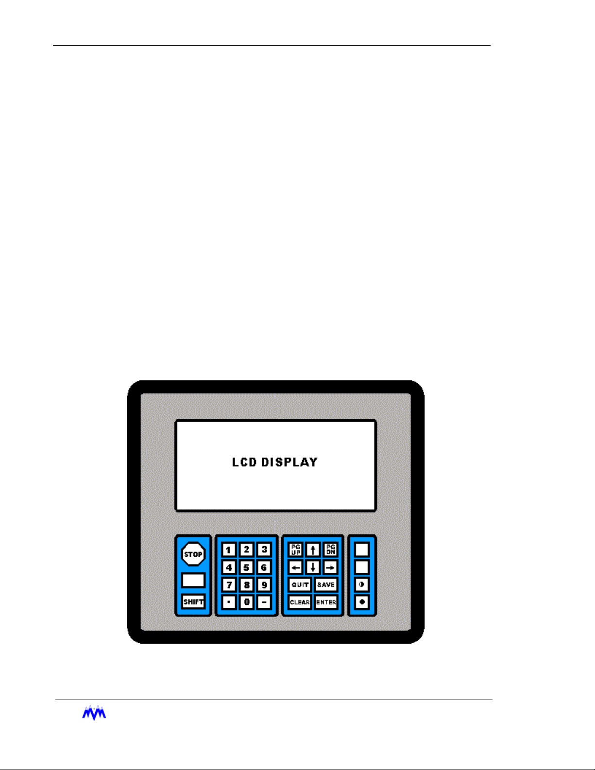
Keypad Functions
The following is a brief summary of the CCS keypad along with a description of its individual
keys. Below is a drawing of the CCS keypad layout.
2-2
M&M R
EFRIGERATION INC
Keypad Diagram
.
Chapter 2: Keypad Functions
STOP
SHIFT
0 – 9
•
-
PG UP
PG DN
QUIT
SAVE
CLEAR
ENTER
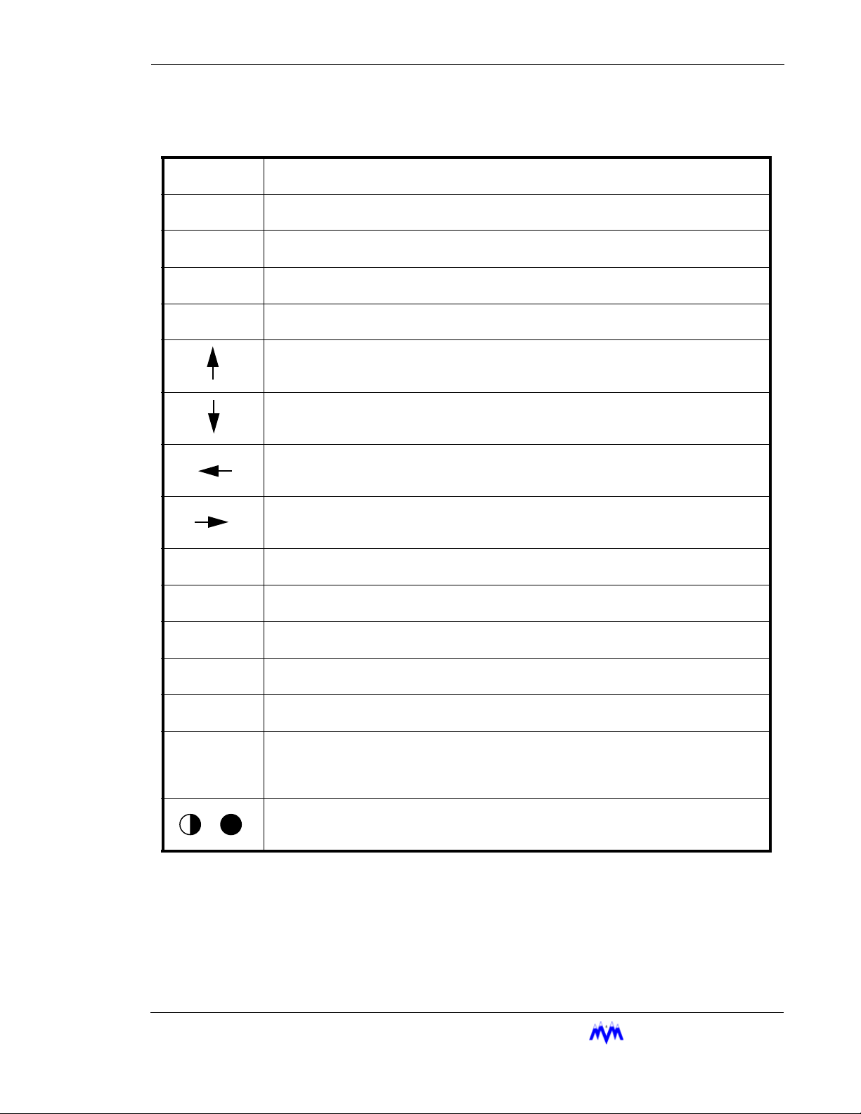
The red STOP key causes an immediate and orderly shutdown of a compressor. This
key usually has no effect on master panels.
The SHIFT key is used to switch control back and forth from the display area to the hot
keys. This key may also be used to scroll between the horizontal pages of a log screen.
The NUMBER keys select menu or hot key options. On data entry screens the number
keys are used to enter numerical data.
The DOT key allows decimal point entry on data entry screens. This key also permits
the user to page forward one full screen at a time on log and status screens.
The MINUS key allows negative number entry on data entry screens. This key also permits the user to page back one full screen at a time on log or status screens.
On data entry or menu screens, the UP ARROW key moves the cursor up to the next
item on the screen.
On data entry or menu screens, the DOWN ARROW key moves the cursor down to the
next item on the screen.
On data entry or menu screens, the LEFT ARROW key moves the cursor left to the next
item on the screen. This key also permits the user to page forward one full screen at a
time on log and status screens.
On data entry or menu screens, the RIGHT ARROW key moves the cursor right to the
next item on the screen. This key also permits the user to page back one full screen at
a time on log and status screens.
The PG UP key is used to page back one full screen at a time for status screens or to
page up to more current data on log screens.
The PG DN key is used to page forward one full screen at a time for status screens or to
page down to older data on log screens.
The QUIT key exits the current screen and displays the previous screen. Pressing the
QUIT key to exit from a data entry screen will result all changed data being lost.
The SAVE key is used with data entry screens to save any changed information. It also
exits the current screen and displays the previous screen.
The CLEAR key within data entry screens will erase the current number field. On the
main status or alarm status screen it acknowledges and clears alarms and failures.
The ENTER key is used within data entry screens on a number field to accept numerical
data or on a selectable field to toggle through the available choices. On menu screens,
the ENTER key will select the highlighted menu item. The ENTER key may also be
used to scroll forward through the status screens.
The CONTRAST keys are used to adjust the display for proper viewing depending on
the ambient light levels. When the desired contrast is achieved, pressing any other key
will lock the current contrast value into memory.
M&M R
EFRIGERATION INC
. 2-3
Standard Screw Compressor - RWB Series
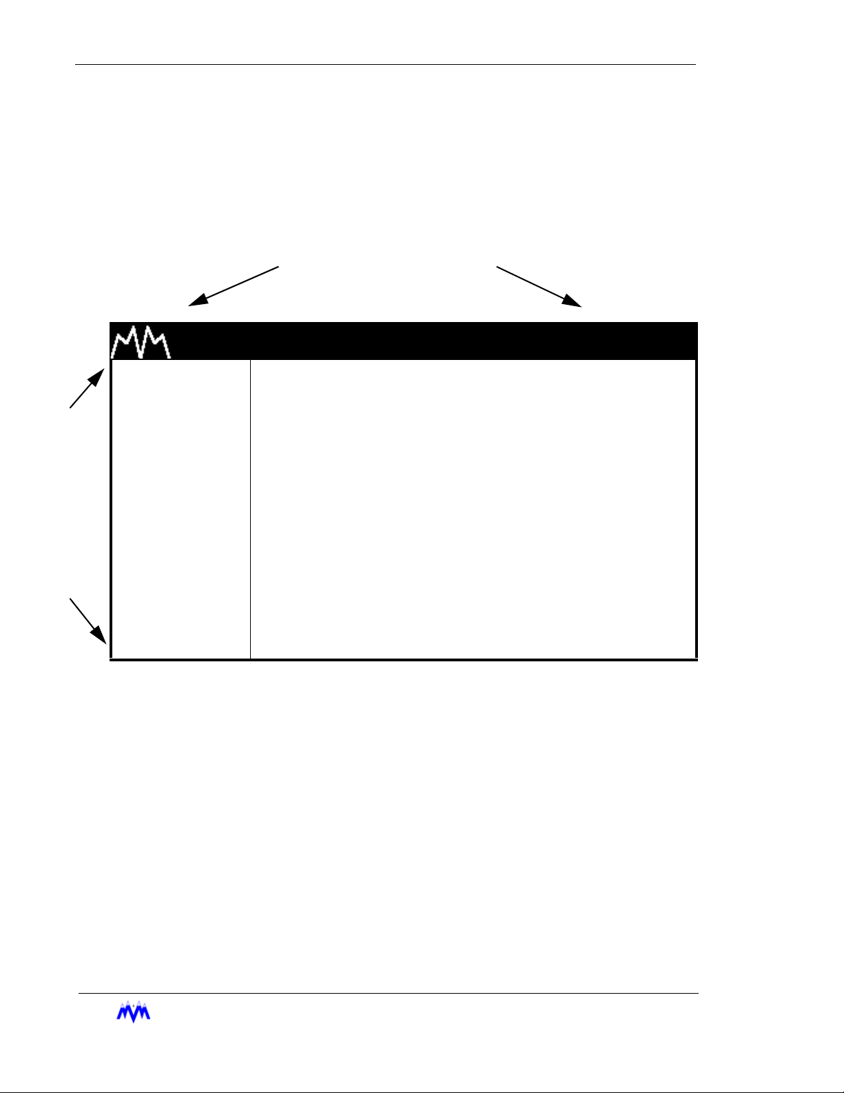
Main Screen Overview
The Main Screen is the name for a set of features common to all large character screens. The
Main Screen is broken down into three areas: display area, hot keys, and title banner. The following drawing shows a representation of the main screen layout and labels each of its various areas.
TITLE BANNER
H
O
T
K
E
Y
S
M & M REFRIGERATION 8:32
1. START
2. STATS
3. MODE
DISPLAY AREA
4. SETPT
5. SCHED
6. CNTRL
7. MISC
8. LOGS
9. MENUS
Main Screen Layout
Title Banner - The top highlighted bar contains the M&M logo and the current time of day and
may only be found on large character screens.
AM
2-4
Display Area - Contains all of the detailed screen information. Large character screens will
use only the designated display area, while small character screens use the entire LCD display.
Hot Keys - The hot keys are a set of system functions, which are found in a column on the left
side of all large character screens. They are the most frequently used functions on the CCS
and allow access to all lower level menus and functions.
EFRIGERATION INC
M&M R
.

Chapter 2: Hot Key Selection
Hot Key Selection
1. Verify Number next to a Hot Key is Highlighted - one of the numbers next to a hot
key should be highlighted and flashing. (This is not the same as having the hot key
command highlighted.)
If there are no numbers highlighted, switch control from the display area to the hot
keys by pressing the SHIFT key.
2. Select Option - use the key pad to select a corresponding option number or use the
arrow keys to move the highlighted area to the desired selection and press ENTER.
3. Alternate Select Option - whenever a status screen is being displayed, a hot key
may be activated by typing the hot key number. This also works on small character
status screens even though the hot keys are not visible.
Screen Types
CCS information is presented to the operator using eight different types of screens. The differ-
ent screen types each use specific data entry and control procedures. The screen types let the
user know which screen type heading to refer to for information on the specific screens' procedures. The following is a list of the eight different screen types.
• Menu Screen - displays a numbered list of options.
• Data Entry Screen - used to modify system control parameters.
• Status Screen - displays real-time system summary data.
• Confirmation Screen - used for verification, gives a choice for a yes or no option.
• Momentary Screen - displays a message for three seconds.
• Information Screen - used to display system information
• Access Screen - a menu type screen with an number input field.
• Log Screen - displays a record of system parameters and actions.
M&M R
EFRIGERATION INC
. 2-5
Standard Screw Compressor - RWB Series
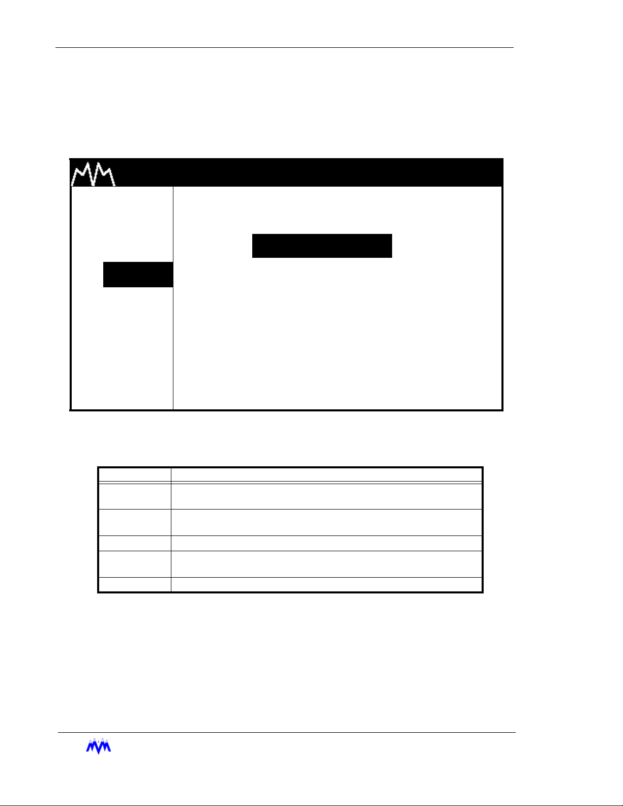
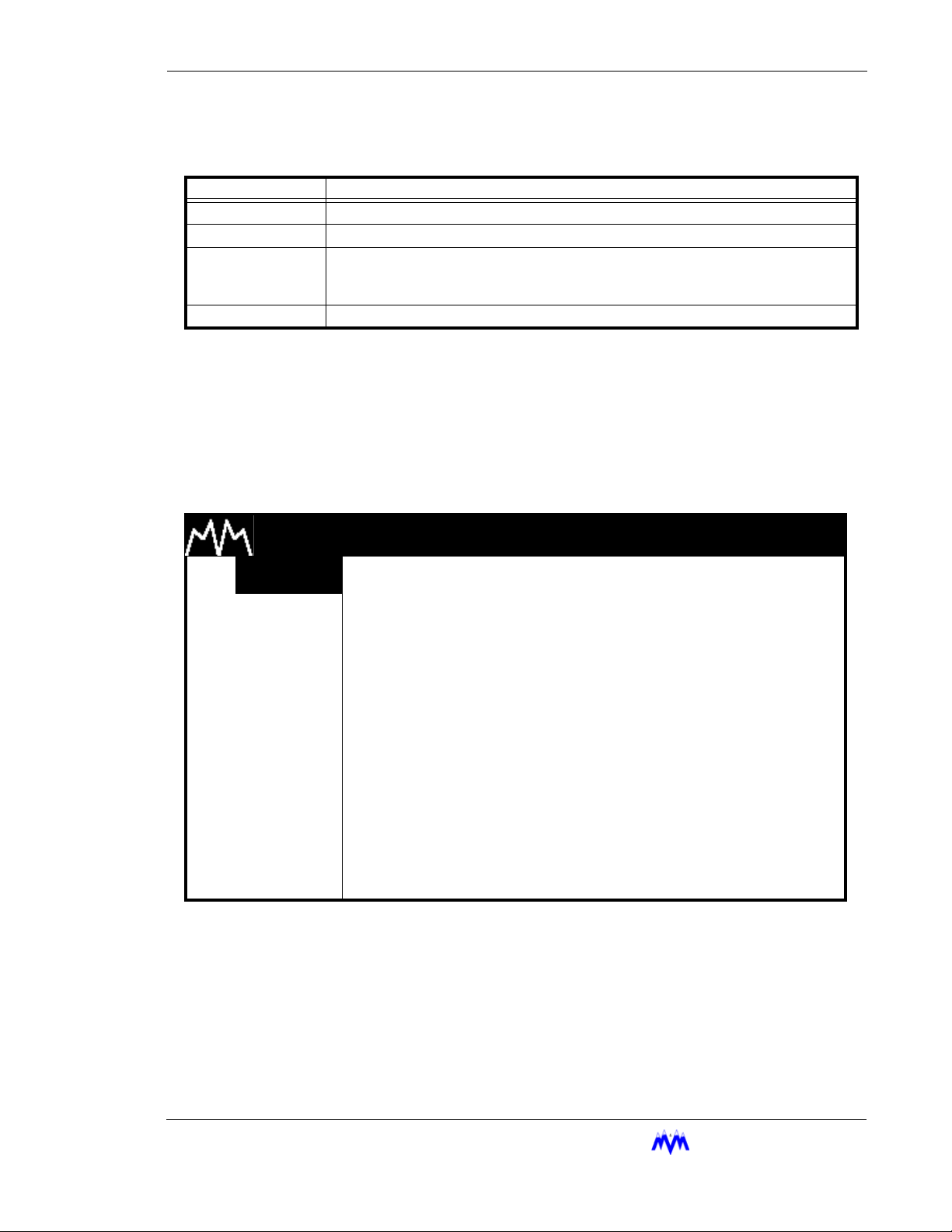
Menu Screens
The Menu screen is used to present the user with choices for various system operations.
Menu screens are found throughout the CCS system. The following is an example of a
menu screen.
M & M REFRIGERATION 8:32
1. START
2. STATS
3. MODE
4. SETPT
5. SCHED
SETPOINT SELECTIONS
1.PRESSURE
2.TEMPERATURE
3.MOTOR CURRENT
6. CNTRL 4.SLIDE VALUE POS
7. MISC
8. LOGS
9. MENUS
Menu Screen
The following table contains a list of the active keys on a menu screen and their function.
AM
2-6
KEYS FUNCTION
SHIFT
NUMBER
KEYPAD
ENTER Used to choose the selection number that is highlighted.
UP/DOWN
ARROW
QUIT Exits from current screen to the previous screen.
EFRIGERATION INC
M&M R
Switches control back and forth between the display area and the hot
keys.
Used to choose a selection number.
Moves the cursor from one selection to the next either up or down.
Menu Screen Keys Table
.
Chapter 2: Screen Types
Menu Selection Procedures - Menu options are chosen similar to hot key options.
1. Verify Cursor Control - Verify that a menu option number is highlighted. If not
use the SHIFT key to transfer cursor control from the hot keys to the display area.
2. Menu Option Selection - Use the number keys corresponding to the desired
menu item or the arrow keys and press ENTER to select the desired menu item.
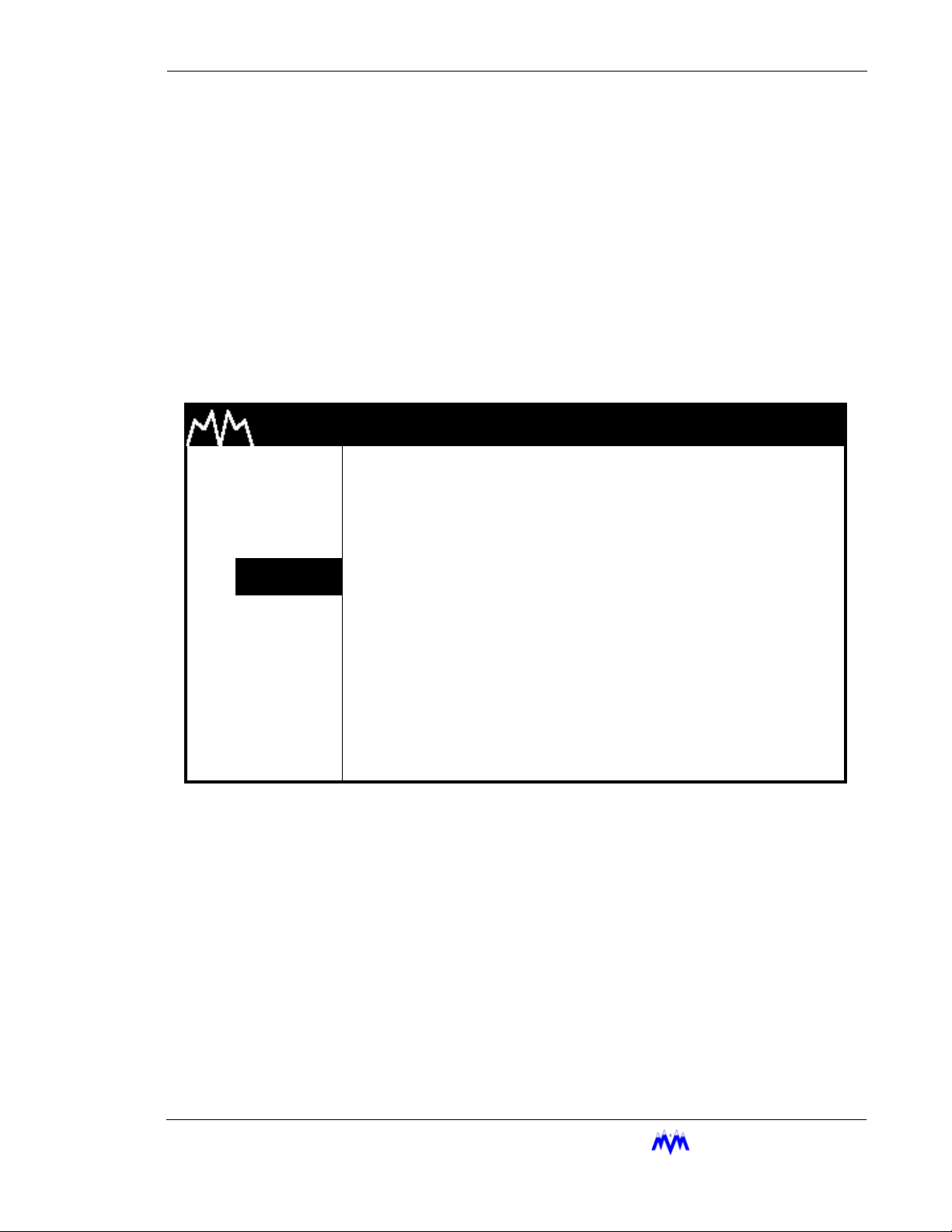
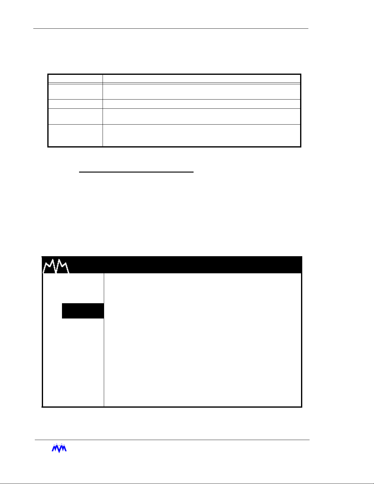
Data Entry Screens
Data Entry screens are user interactive screens, which allow the user to change or input
system data. These screens contain a special cursor to signify the field type at the cursor
location. The cursor can be moved throughout the screen to indicate each field location.
The following is an example of a data entry screen.
M & M REFRIGERATION 8:32
1. START
2. STATS
3. MODE
4.
SETPT
5. SCHED
6. CNTRL
7. MISC
8. LOGS
9. MENUS
NOTE: D
ata Entry screens may also contain information for reference purposes that is not
changeable.
OIL TEMP SETPTS
HIGH FAILURE XXX.X
HIGH ALARM XXX.X
HEATER CONTROL XXX.X
LOW ALARM XXX.X
LOW FAILURE XXX.X
Data Entry Screen
AM
DEGF
DEGF
DEGF
DEGF
DEGF
M&M R
EFRIGERATION INC
. 2-7
Standard Screw Compressor - RWB Series
The following table contains a list of the active keys on a data entry screen and their function.
KEYS FUNCTION
NUMBER
KEYPAD
ENTER
ARROW
KEYS
CLEAR
SAVE Exits from the current screen and all new data is saved.
QUIT Exits from the current screen and all new data is lost.
Used to enter numerical data.
Toggles through the available choices on a selectable field. On a number field the
ENTER
Moves the cursor from one field to the next either up, down, left or right. Any of the
arrow keys can also be used to accept the data entered on a number field.
Will clear the current numerical field. The
key is used to accept entered data and move to next field.
A data entry screen may contain both numerical input and selectable fields, which are identified by different cursors as shown in the following table.
CLEAR
Data Screen Keys
key is not active on selectable fields.
CURSOR FUNCTION
> Selectable cursor, indicates a selectable field.
* Numerical input cursor, indicates a number field.
“ String input cursor, indicates an alphanumeric string field.
X Hexadecimal input cursor, indicates hexadecimal number field.
Data Entry Screen Cursor Table
Data Entry Procedures
1. Verify Screen Type - One of the special cursors must appear on the screen. If
the cursor did not appear you are not on a data entry screen.
2. Change Fields - Use the arrow keys to move the cursor to the desired field.
3. Enter Data - Enter the desired numerical data or select the desired selectable
depending on field type.
4. SAVE OR QUIT - Upon completing the changing of data the user may press
SAVE to save all newly entered data and return to the previous screen. If the
user presses QUIT the entered data will not be saved. After pressing QUIT, a
confirmation screen will ask the user to verify the desire to lose all changes
entered.
Field Types
2-8
M&M R
This section discusses the procedures used to work with each of the field types
as well as the general procedures that apply to all number entry fields. The following information applies to any field when entering numerical data:
Decimal Number Entry - If the data you wish to enter has a zero in the decimal
place there is no need to enter " .0 ". Simply enter the whole number value.
EFRIGERATION INC
.

Chapter 2: Screen Types
Arrow Keys - The arrow keys will accept the entered data and move the cursor to
the next field.
Errors - A flashing error message tells the user that the entered data is not within
an acceptable range for the field. The user must clear the error before proceeding. To clear an error message the operator presses the CLEAR key.
Restoring Valid Data - The user can clear and re-enter data from any field prior
to leaving the field. If the arrow key or the ENTER key is used to move off the
field after it has been cleared, the previously entered valid data will be restored to
the field.
Selectable Fields
A selectable field gives the user a choice of inputs from which to toggle
through, and is recognized by the ">" cursor preceding it.
1. Verify Cursor Type - locate the ">" selection cursor.
2. ENTER Key - cycles the user through the available selections.
3. Arrow Keys - move to the next field and accept the selection.
Numerical Data Input Fields
A numerical field is used to enter control data, and is recognized by the "*"
cursor preceding it.
1. Verify Cursor Type - locate the "*" numeric input cursor.
2. Number Keypad - press the number keys that correspond to the
number you wish displayed. Use the decimal and minus keys where
applicable. Each field will limit the user to a maximum number of
whole and decimal numbers for that specific field.
3. ENTER/Arrow Keys - move to the next field and accept the entered
number.
4. Verify Cursor Type - Upon pressing the ENTER or DOWN ARROW
key, if the cursor moves across to the units column and changes to
the ">" selectable cursor, the user is in a suction pressure field which
is described in the next section.
Absolute Pressure Fields
This field is actually a combination of numerical and selectable fields. The
selectable or units section of the field allows the user to adjust the units to
select vacuum or non-vacuum ranges.
1. Verify Cursor Type - locate the "*" numeric input cursor.
2. Number Keypad - press the number keys that correspond to the
number you wish displayed. Use the decimal and minus keys where
applicable. If the numeric field already has the correct data and only
the units need to be adjusted, re-enter the existing numerical data
and press ENTER.
EFRIGERATION INC
M&M R
. 2-9

Standard Screw Compressor - RWB Series
3. ENTER/Arrow Keys - locks in the numerical data and moves the
cursor across to the units section of the field.
4. Verify Cursor Type - locate the ">" selection cursor next to the units
section.
5. ENTER - cycles between possible units selections.
6. Arrow Keys - move to the next field and accept the entered data.
7. Errors - If an error occurs because the value entered is out of range
the CLEAR key will clear the field and return the user to the number
portion of the field.
Time Fields
The time field is a special case numerical field used to enter time data.
1. Verify Cursor Type - locate the "*" numeric input cursor.
2. Number Keypad - use the number keys to enter the time you wish
displayed. For example, to input the time 5:59 press 0559, the system automatically moves from hours to the minutes. The ":" is automatically entered in a time field. This field will allow for whole number
acceptance. For example to set the time 8:00 the user may type 08
and press ENTER. The time on the screen will appear as 08:00. It
should be noted that time fields may be entered in 12-hour or 24hour format depending on the system configuration. If the system is
in 12-hour format the user will be prompted to select "AM" or "PM"
using a selectable field after a number is entered.
3. Arrow Keys - move to the next field and accept the entered time.
Date Fields
The Date field is a special case numerical entry field used to enter the date.
1. Verify Cursor Type - locate the "*" numeric input cursor.
2. Number Keypad - use the number keys to enter the date you wish
displayed. For example, to enter the date 1/1/91 the user would type
in 010191, the system automatically moves from the month to the
day and then to the year. The "/" slash symbol is entered for you.
3. Arrow Keys - move to the next field and accept the entered date.
String Fields
The String field is a special case alphanumeric entry field. It is similar to a
selectable field but each character in the string may be selected from the list
of all-possible letters, numbers, and special characters.
1. Verify Cursor Type - locate the " “ " string input cursor.
2. Enter Key - Pressing the ENTER key first will clear the current contents and start entering characters. The ENTER key is primarily used
to cycle through the available selections for the current character
positions.
2-10
M&M R
EFRIGERATION INC
.

Chapter 2: Screen Types
3. “.” Key - Selecting the Period (.) key puts the field into edit mode
and allows the current contents of the field to be entered.
4. Arrow Keys - Allows you to move within a field to different charac-
ters.
5. Number Keys - These keys are used to enter numbers into a charac-
ter.
6. Clear Key - This key is used to clear the contents of the entire field.
7. Entering a space - If a space is allowed in the field, an “_” will be
available in the character list. Selecting this character will result in a
space being inserted in the string. All trailing spaces are eliminated.
Telephone Number Field
The Telephone Number field is a special case alphanumeric entry field. It is
similar to a string field but only allows numbers and several special characters
required for telephone numbers.
1. Verify Cursor Type - locate the " “ " string input cursor.
2. Enter Key - Pressing the ENTER key first will clear the current contents and start entering characters. The ENTER key is primarily used
to cycle through the available selections for the current character
positions.
3. “.” Key - Selecting the Period (.) key puts the field into edit mode
and allows the current contents of the field to be entered.
4. Arrow Keys - Allows you to move within a field to different charac-
ters.
5. Number Keys - These keys are used to enter numbers into a charac-
ter.
6. Clear Key - This key is used to clear the contents of the entire field.
7. Entering a space - If a space is allowed in the field, an “_” will be
available in the character list. Selecting this character will result in a
space being inserted in the string. All trailing spaces are eliminated.
Hexadecimal Fields
The Hexadecimal Field is a special case alphanumeric entry field. It is similar
to a string field but only allows numbers and several special characters
required for hexadecimal numbers.
1. Verify Cursor Type - locate the " “ " string input cursor.
2. Enter Key - Pressing the ENTER key first will clear the current contents and start entering characters. The ENTER key is primarily used
to cycle through the available selections for the current character
positions.
3. “.” Key - Selecting the Period (.) key puts the field into edit mode
and allows the current contents of the field to be entered.
EFRIGERATION INC
M&M R
. 2-11
Standard Screw Compressor - RWB Series
4. Arrow Keys - Allows you to move within a field to different charac-
ters.
5. Number Keys - These keys are used to enter numbers into a char-
acter.
6. Clear Key - This key is used to clear the contens of the entire field.
7. Entering a space - If a space is allowed in the field, an “_” will be
available in the character list. Selecting this character will result in a
space being inserted in the string. All trailing spaces are eliminated.
Status Screens
Status screens are used to display a summary of significant system information. The main
Status screen in a system is usually a large character text screen or graphics screen and
is the default screen displayed on the LCD. The main Status screen will be replaced by
the Active Alarm and Failure screen when a new alarm or failure exists or by the AutoStart Warning screen if the compressor is online and ready to start.
The operator may view each of the system's available status screens by scrolling through
using the ENTER, PG UP, PG DN, Right Arrow, or Left Arrow keys. The number of status
screens on a system will vary depending upon the individual system's configuration.
Another feature of the system is that it will automatically return to the main status screen
after 10 minutes of no keyboard activity. Below is an example of a Status screen.
M & M REFRIGERATION 8:32
1. START SY XXX.X
2.
STATS
SP XXX.X
3. MODE DP XXX.X
4. SETPT OP XXX.X
5. SCHED OF XXX.X
6. CNTRL
7. MISC
OF 0.1
SV XXX
PSIG |
PSIG |
PSIG |
PSIG |
PSIG |
PSIG |
PCT |
MA XXX.X
ST XXX.X
DT XXX.X
OT XXX.X
OS XXX.X
PT XXX.X
AMPS
DEGF
DEGF
DEGF
DEGF
DEGF
8. LOGS
9. MENUS RUN-TRIM SEQ NORM
Status Screen
AM
2-12
M&M R
EFRIGERATION INC
.
Chapter 2: Screen Types
The following table contains a list of the active keys on a status screen and their function.
KEY FUNCTION
SHIFT Switches control between the display area and the hot key options.
ENTER Scrolls through the set of available status screens.
PG UP/PG DN/
RIGHT/LEFT
ARROWS
QUIT Returns the user to the main status screen.
Confirmation Screens
A Confirmation screen is used to ask the user to confirm a selection by answering a question. This screen usually appears after the user has altered system parameters and then
presses the QUIT key or, to verify a system control request. Below is an example of a con-
firmation screen.
Pages forward or back through the available status screens.
Status Screen Keys
M & M REFRIGERATION 8:32
1. START
2. STATS
3. MODE
4. SETPT
5. SCHED
6. CNTRL
7. MISC
8. LOGS
9. MENUS
AM
VERIFY
COMPRESSOR ONLINE
1.NO
2.YES
Confirmation Screen
M&M R
EFRIGERATION INC
. 2-13
Standard Screw Compressor - RWB Series
The following table contains a list of the active keys on a confirmation screen and their
function.
KEYS FUNCTION
NUMBER
KEYPAD
ENTER Used to select the highlighted response number.
UP/DOWN
ARROWS
QUIT
Confirmation Screen Procedures
Number Keypad - Use the keypad to match your response with the numerical
choices shown on the screen or press QUIT to exit the screen.
Used to select a response number.
Moves the cursor from one selection to the next, either up or down.
Exits from the current screen to the previous screen. Same as selecting NO for
most screens or YES when quitting from a data entry screen after making
changes.
Confirmation Screen Keys
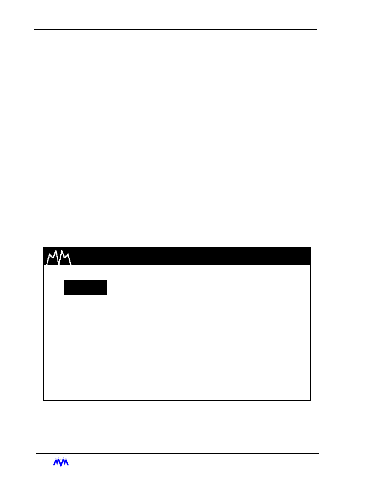
Momentary Screens
The Momentary screen is used to verify certain user selections by displaying an informative message for three seconds. Rather than waiting for the entire three second time to
elapse, the operator may press the QUIT key to end viewing of the message. The follow-
ing is an example of a momentary screen.
M & M REFRIGERATION 8:32
1. START
2. STATS
3. MODE
4. SETPT
5. SCHED
6. CNTRL
7. MISC
8. LOGS
AM
AUTOMATIC MODE
ENABLED
9. MENUS
2-14
M&M R
EFRIGERATION INC
Momentary Screen
.
Chapter 2: Screen Types
The following table contains a list of the active keys on a momentary screen and their
function.
KEY FUNCTION
QUIT Stops display of the message before the three second time limit expires.
Momentary Screen Keys
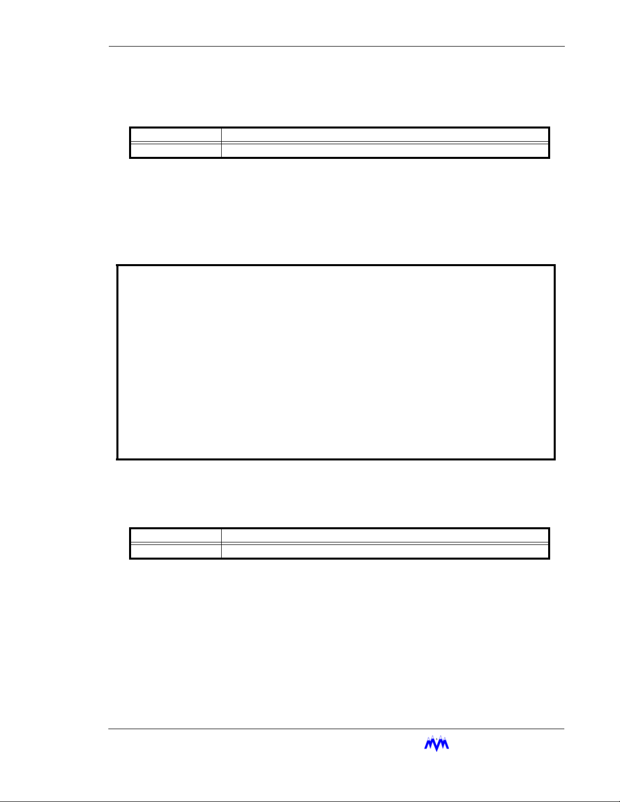
Information Screens
Information screens are used to display system data to the user. The information on
these screens may be real-time data or a snapshot of data at the time the screen is
first displayed.
SYSTEM INFORMATION day mm/dd/yy hh:mm:ss
M & M REFRIGERATION INC, COPYRIGHT 1991-2001 FRAME STATISTICS
F0 F1 F2 F3
M&M SCREW day mm dd yyyy hh:mm:ss v1.00 ---- ---- ---- --- MEMORY INITIALIZED : mm/dd/yy hh:mm:ss MAX : xxxx xxxx xxxx xxxx
SYSTEM LAST RESET : mm/dd/yy hh:mm:ss AVG : xxxx xxxx xxxx xxxx
CURRENT TIME : mm/dd/yy hh:mm:ss day MIN : xxxx xxxx xxxx xxxx
TIMER STATUS : 0 of 0 MAX: 0
REFRIGERANT : R717 SEQUENCED : NO LUBE SYSTEM : NO PUMP
NETWORK CONTROL : NO REMOTE : NO UNLOAD SOL : N/OPEN
BYPASS SOL : NO AUTO-REMOTE : NO
ECONOMIZER SOL : NO PROCESS TEMP : NO
VARIABLE VI : NONE MODEM : NO
Information Screen
The following table contains a list of the active keys on an information screen and their
function.
KEY FUNCTION
QUIT Exits from current screen to the previous screen.
Information Screen Keys
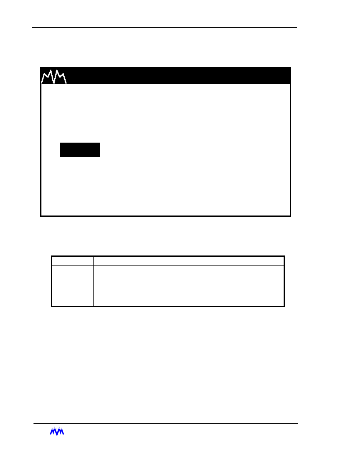
Access Screens
The Access screen is used to index the user into a larger set of screens. This screen is
typically used in cases where more than eight screens are available for a particular option.
The Access screen will perform error checking on the number entered. For example, if the
screen is used to access the daily schedules and the number eight is entered, the input
area will flash ERROR since there are only seven possible schedules. The user will be
M&M R
EFRIGERATION INC
. 2-15
Standard Screw Compressor - RWB Series
required to clear the error and enter a correct value. The data entry process is described
in more detail in the data entry section. The following is an example of an access screen.
M & M REFRIGERATION 8:32
1. START
2. STATS
3. MODE
4. SETPT
5. SCHED
6. CNTRL
7. MISC
8. LOGS
9. MENUS
The following table contains a list of the active keys on an access screen and their function.
AM
DAILY SCHEDULES
ENTER SCHEDULE (1-7) xxx
Access Screen
KEYS FUNCTION
SHIFT Switches control back and forth between the display area and the hot keys.
NUMBER
KEYPAD
ENTER Used to accept the selection number that is entered.
QUIT Exits from current screen to the previous screen.
Used to enter a number selection.
Access Screen Keys
2-16
M&M R
EFRIGERATION INC
.
 Loading...